VMI Micro CAP 232 User manual

For Intermediate & Advanced Fliers.
SAFETY PRECAUTIONS
This radio control model is not a toy!
Fist-time builders should seek advice from people having building
Experience in order to assemble the model correctly and to produce
Its performance to full extent.
Assemble this kit only in places out of children’s reach!
Take enough safety precautions prior to operating this model.
You are responsible for this model’s assembly and safe operation!
Always keep this instruction manual ready at hand for quick
Reference, even after completing the assembly.
Notice:
By the time the Yak arrives in your shop, it will have endured several climate changes.
As a result you may find some wrinkles in the covering and wing or Fus. Part maybe
have some twisted. This is not a manufacturing defect. Please take a few moments
with your iron or heat gun to remove any wrinkles and correct all twisted parts. Iron
over all the edges to ensure they are sealed.
This Products Produce by P & D Products Company
4/F., 162 Temple St., Kln. Hong Kong Fax: 852-8220 6288
E-mail:
AUTHORIZED DEALER: Versailles Modeles Import
8,rue du vieux Versailles 78000 Versailles
E-mail: info@versaillesmodes.com web: www.versaillesmodeles.com

P01
Install Gold plug to connected your ESC. And
motor.
N
otice: before you install the ESC. You need to
solid ESC. And motor connector, and then
connect them together. If you find the motor are
revised run when you test run, you can correct
by revered any two connector. Or you can check
your motor and ESC. Manual.
P02
Install the Prop. As show.
P03
Drill a 2mm hole on the gearbox as show.

P04
Find the Right thrust spacer.
P05
Put the gearbox set on the Fus. And make a mark
as the show.
P06
Remover covering as the show.

P07
Glue the right thrust spacer on Fus. As show.
N
otice. Thicker end was toward to tail.
P08
Install the gearbox on motor mount as show.
You will find some right thrust will show.
The actually need was after you test flying than
adjust it again by a bit light sanding the right
thrust spacer.
P09
Fix the gearbox on motor mount as the show.

P10
Use hobby knife make two slots than use the
wire bent tight up the ESC. or use double foam
tape fix the ESC.
P11
Attached the magic tape as show.
P12
Install it on fus. As show.
N
otice: if you feel the CG. Point not site your
flying style, you can install the battery

P13
Tight up the battery as show.
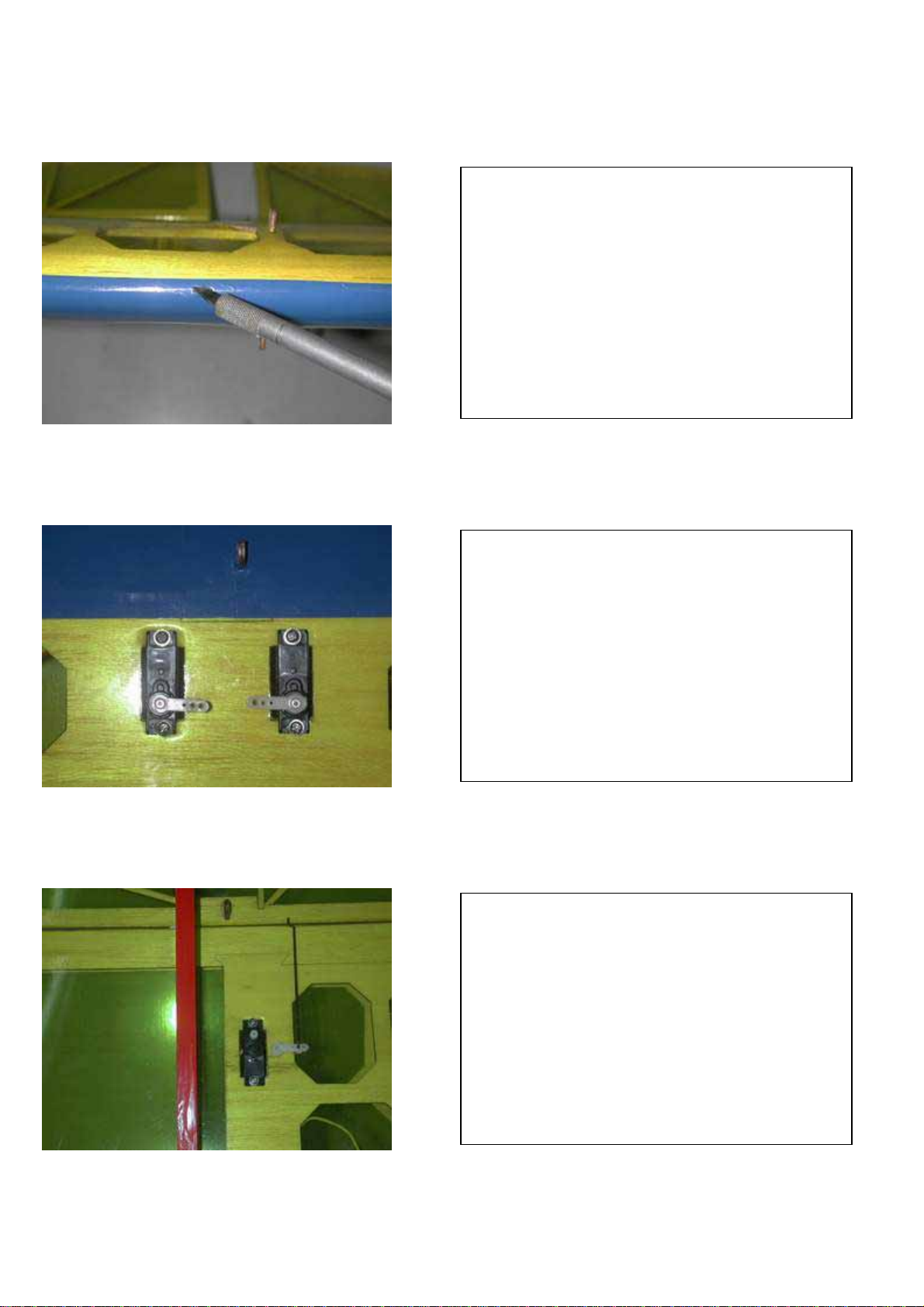
P14
Heat the knife.
P15
Cut the a small hole with heat knife tip on the
cover for the push rod holder.

P16
Find the push rod holder four piece for each side.
P17
Install the four push rod holder four pieces for
each side.
Install the Rudder and Elevator push rod in each
side.
N
otice: the longer one pushrod is Rudder push
rod on left hand side.
P18
Install the two hinges inside the Rudder hinges
slot. Then glue it with CA. glue.

P19
Install the Rudder on the Fus. As show.
P20
Cut out the covering and glue the Rudder control
horn left hand side.
Then install the push rod Z end with Rudder
control horn as show.
P21
Bend the push rod end to be a “L” . Then inset to
the Rudder control horn as show.
N
otice: before you bend the push rod end you
must made sure other end of push rod was in
right place of the servo center.

P22
Find the one Elevator control horn and two
Stabilizer mount plat.
P23
Cut out covering and install the Elevator control
horn at right hand side.
Then glue it together with GA.
P24
Cut out covering and install two Stabilizer moun
t
p
lat.
Then glue it together with Thick GA.

P25
Install the Stabilizer inside the Fus. Slot and fix
it with two TP. Screw (2 X 10mm).
P26
Bend the end of the Elevator push rod and inset
it with the Elevator control horn as show.
N
otice: before you bend the push rod end you
must made sure other end of push rod was in
right place of the servo center.
P27
Check the Rudder and Elevator push rod install
as the show.

P28
Install the main wheel on the landing gear as
show.
P29
Install the wheel lock and use Thin CA. to glue it
with very carefully. And made sure wheel was
free after you fix the wheel lock.
P30
Install the landing gear on the fus. As show.

P31
Use the wire bond to tight up landing gear.
N
otice: if you want put the fus. Inside the carry
box again after flying. You may need to remove
the landing after you flying.
P32
Find the two Aileron control horn and install
them at the LE. of Aileron as show and glue it
with CA.
P33
Install the Aileron servo as show.

P34
Install the Aileron push rod Z end to the Aileron
control horn.
Then bend other end for the servo horn.
P35
Install the push rod to servo horn and fix it with
p
ush rod keeper. Glue it with CA. with carefully.
Then check the push rod was free or not.
P36
Use hobby knife cut off covering on wing panel
as show.
P37
Install the receiver and connect of servo and
check them all in correct channel.
Then use hobby knife to open a small hole for
the Antenna out and the BEC. Wire inside to
wing.
P38
Install the Rudder and Elevator servo as show.
P39
Remove the Aileron push rod first then install
the wing from one side to the FUS.

P40
Find the Four 2 X 13mm TP. Screw and lock
washer.
P41
Glue four piece plastics washer for wing fix
screw.
P42
Fix the wing on to the Fus. With four TP. Screw
(2 X 10mm).

P43
Install the Rudder and Elevator push rod same
the Aileron push rod.
N
otice: Before you install the servo horn , you
need to turn on your radio to check the servo was
in neutral point.
P44
Remove one of Aileron push rod and servo
control horn before you install the wing panel or
remove the wing panel from Fus.
P45
Put out the Antenna from small hole then fix the
Antenna by tape.
connect the BEC. To receiver thought the small
hole.
Then find out a covering film in kit.

P46
After you check and adjust all the radio control
was correct.
Then use covering cover the hole that you open
for receiver install.
P47
Find two decal sheet and one tans film.
P48
Remove the tans film.

P49
Apply the tans film to decal sheet and remove
the decal from the base sheet.
P50
Then remove the tans film carefully from the
wing panel.
P51
The finished wing are show.

If you choice ATPro OX.2209-28 Out runner
motor.
You need four M3 X 4mm screw.
MP15 or MP12 Propeller adaptor.
MP12 Propeller adaptor.
MP15 Propeller adaptor.

The finished wing are show.
Drill two 1.5mm hole as show.
Fix the motor mount with two 2.5mmTP. screw.
Table of contents
Popular Toy manuals by other brands


Fisher-Price
Fisher-Price digital Studio Arts & Crafts manual

OA Composites
OA Composites F3Klaus NRJ Building instructions

Fisher-Price
Fisher-Price ALPHA BUS B4860 instructions

Nine Eagles
Nine Eagles Solo PRO180 3D instruction manual

ScienceSeeds
ScienceSeeds MAGIC PENNY BOX instructions

Hasbro
Hasbro Disney The Lion King MIGHTY ROAR SIMBA quick guide