VMIC VMIPMC-6101 User manual

Artisan Technology Group is your source for quality
new and certied-used/pre-owned equipment
• FAST SHIPPING AND
DELIVERY
• TENS OF THOUSANDS OF
IN-STOCK ITEMS
• EQUIPMENT DEMOS
• HUNDREDS OF
MANUFACTURERS
SUPPORTED
• LEASING/MONTHLY
RENTALS
• ITAR CERTIFIED
SECURE ASSET SOLUTIONS
SERVICE CENTER REPAIRS
Experienced engineers and technicians on staff
at our full-service, in-house repair center
WE BUY USED EQUIPMENT
Sell your excess, underutilized, and idle used equipment
We also offer credit for buy-backs and trade-ins
www.artisantg.com/WeBuyEquipment
REMOTE INSPECTION
Remotely inspect equipment before purchasing with
our interactive website at www.instraview.com
LOOKING FOR MORE INFORMATION?
Visit us on the web at www.artisantg.com for more
information on price quotations, drivers, technical
specications, manuals, and documentation
Contact us: (888) 88-SOURCE | sales@artisantg.com | www.artisantg.com
SM
View
Instra

12090 South Memorial Parkway
Huntsville, Alabama 35803-3308, USA
(256) 880-0444 w(800) 322-3616 wFax: (256) 882-0859
VMIPMC-6101
PMC-Based Copper Gigabit Ethernet
Adapter
Installation Guide
522-756101-000 Rev. B
Artisan Technology Group - Quality Instrumentation ... Guaranteed | (888) 88-SOURCE | www.artisantg.com

12090 South Memorial Parkway
Huntsville, Alabama 35803-3308, USA
(256) 880-0444 w(800) 322-3616 wFax: (256) 882-0859
Artisan Technology Group - Quality Instrumentation ... Guaranteed | (888) 88-SOURCE | www.artisantg.com

© Copyright 2001. The information in this document has been carefully checked and is believed to be entirely reliable.
While all reasonable efforts to ensure accuracy have been taken in the preparation of this manual, VMIC assumes no
responsibility resulting from omissions or errors in this manual, or from the use of information contained herein.
VMIC reserves the right to make any changes, without notice, to this or any of VMIC’s products to improve reliability,
performance, function, or design.
VMIC does not assume any liability arising out of the application or use of any product or circuit described herein; nor
does VMIC convey any license under its patent rights or the rights of others.
For warranty and repair policies, refer to VMIC’s Standard Conditions of Sale.
AMXbus, BITMODULE, COSMODULE, DMAbus, IOMax, IOWorks Foundation, IOWorks Manager, IOWorks Server,
MAGICWARE, MEGAMODULE, PLC ACCELERATOR (ACCELERATION), Quick Link, RTnet, Soft Logic Link, SRTbus,
TESTCAL, “The Next Generation PLC”, The PLC Connection, TURBOMODULE, UCLIO, UIOD, UPLC, Visual Soft Logic
Control(ler),
VMEaccess
, VMEbus Access
, VMEmanager
,
VMEmonitor
,VMEnet, VMEnet II, and
VMEprobe
are
trademarks and The I/O Experts, The I/O Systems Experts, The Soft Logic Experts, and The Total Solutions Provider are
service marks of VMIC.
COPYRIGHT AND TRADEMARKS
VMIC
All Rights Reserved
This document shall not be duplicated, nor its contents used for any
purpose, unless granted express written permission from VMIC.
The I/O man figure, IOWorks, IOWorks man figure, UIOC, Visual IOWorks, the VMIC logo, and
WinUIOC
are
registered trademarks of VMIC.
ActiveX, Microsoft, Microsoft Access, MS-DOS, Visual Basic, Visual C++, Win32, Windows, Windows NT, and XENIX
are registered trademarks of Microsoft Corporation.
Celeron and MMX are trademarks, and Intel and Pentium are registered trademarks of Intel Corporation.
PICMG and CompactPCI are registered trademarks of PCI Industrial Computer Manufacturers’ Group.
Other registered trademarks are the property of their respective owners.
(I/O man figure) (IOWorks man figure)
Artisan Technology Group - Quality Instrumentation ... Guaranteed | (888) 88-SOURCE | www.artisantg.com

12090 South Memorial Parkway
Huntsville, Alabama 35803-3308, USA
(256) 880-0444 w(800) 322-3616 wFax: (256) 882-0859
Artisan Technology Group - Quality Instrumentation ... Guaranteed | (888) 88-SOURCE | www.artisantg.com

5
Table of Contents
List of Figures . . . . . . . . . . . . . . . . . . . . . . . . . . . . . . . . . . . . . . . . . . . . . . . . . . . . . . . . . . . . . . . . . . . . . 7
List of Tables . . . . . . . . . . . . . . . . . . . . . . . . . . . . . . . . . . . . . . . . . . . . . . . . . . . . . . . . . . . . . . . . . . . . . . 9
Overview. . . . . . . . . . . . . . . . . . . . . . . . . . . . . . . . . . . . . . . . . . . . . . . . . . . . . . . . . . . . . . . . . . . . . . . . . 11
Functional Description . . . . . . . . . . . . . . . . . . . . . . . . . . . . . . . . . . . . . . . . . . . . . . . . . . . . . . . . . . . . 12
PCI Core Interface . . . . . . . . . . . . . . . . . . . . . . . . . . . . . . . . . . . . . . . . . . . . . . . . . . . . . . . . . . . . 12
Hardware Installation . . . . . . . . . . . . . . . . . . . . . . . . . . . . . . . . . . . . . . . . . . . . . . . . . . . . . . . . . . 13
Media Connection . . . . . . . . . . . . . . . . . . . . . . . . . . . . . . . . . . . . . . . . . . . . . . . . . . . . . . . . . . . . 13
Reference Material List. . . . . . . . . . . . . . . . . . . . . . . . . . . . . . . . . . . . . . . . . . . . . . . . . . . . . . . . . . . . 14
Physical Description and Specifications. . . . . . . . . . . . . . . . . . . . . . . . . . . . . . . . . . . . . . . . . . . . 14
Safety Summary. . . . . . . . . . . . . . . . . . . . . . . . . . . . . . . . . . . . . . . . . . . . . . . . . . . . . . . . . . . . . . . . . 15
Ground the System . . . . . . . . . . . . . . . . . . . . . . . . . . . . . . . . . . . . . . . . . . . . . . . . . . . . . . . . . . . 15
Do Not Operate in an Explosive Atmosphere . . . . . . . . . . . . . . . . . . . . . . . . . . . . . . . . . . . . . . . 15
Keep Away from Live Circuits . . . . . . . . . . . . . . . . . . . . . . . . . . . . . . . . . . . . . . . . . . . . . . . . . . .15
Do Not Service or Adjust Alone . . . . . . . . . . . . . . . . . . . . . . . . . . . . . . . . . . . . . . . . . . . . . . . . . . 15
Do Not Substitute Parts or Modify System. . . . . . . . . . . . . . . . . . . . . . . . . . . . . . . . . . . . . . . . . . 15
Dangerous Procedure Warnings . . . . . . . . . . . . . . . . . . . . . . . . . . . . . . . . . . . . . . . . . . . . . . . . . 15
Safety Symbols Used in This Manual. . . . . . . . . . . . . . . . . . . . . . . . . . . . . . . . . . . . . . . . . . . . . . . . . 16
Chapter 1 - Configuration and Installation . . . . . . . . . . . . . . . . . . . . . . . . . . . . . . . . . . . . . . . . . . . . . . 17
Unpacking Procedures . . . . . . . . . . . . . . . . . . . . . . . . . . . . . . . . . . . . . . . . . . . . . . . . . . . . . . . . . . . . 18
System Requirements . . . . . . . . . . . . . . . . . . . . . . . . . . . . . . . . . . . . . . . . . . . . . . . . . . . . . . . . . 18
Software Drivers. . . . . . . . . . . . . . . . . . . . . . . . . . . . . . . . . . . . . . . . . . . . . . . . . . . . . . . . . . . . . . 18
Physical Installation . . . . . . . . . . . . . . . . . . . . . . . . . . . . . . . . . . . . . . . . . . . . . . . . . . . . . . . . . . . . . . 19
Driver Installation . . . . . . . . . . . . . . . . . . . . . . . . . . . . . . . . . . . . . . . . . . . . . . . . . . . . . . . . . . . . . 20
Cable Type and Installation . . . . . . . . . . . . . . . . . . . . . . . . . . . . . . . . . . . . . . . . . . . . . . . . . . . . . . . . 21
Attach the Network Cable . . . . . . . . . . . . . . . . . . . . . . . . . . . . . . . . . . . . . . . . . . . . . . . . . . . . . . 21
Artisan Technology Group - Quality Instrumentation ... Guaranteed | (888) 88-SOURCE | www.artisantg.com

VMIPMC-6101 PMC-Base Copper Gigabit Ethernet Adapter
6
Front Panel Status LEDs. . . . . . . . . . . . . . . . . . . . . . . . . . . . . . . . . . . . . . . . . . . . . . . . . . . . . . . . . . 23
Additional Setup and Configuration. . . . . . . . . . . . . . . . . . . . . . . . . . . . . . . . . . . . . . . . . . . . . . . . . . 24
Troubleshooting. . . . . . . . . . . . . . . . . . . . . . . . . . . . . . . . . . . . . . . . . . . . . . . . . . . . . . . . . . . . . . . . . 25
Test the Adapter . . . . . . . . . . . . . . . . . . . . . . . . . . . . . . . . . . . . . . . . . . . . . . . . . . . . . . . . . . . . . 25
Windows NT Procedure . . . . . . . . . . . . . . . . . . . . . . . . . . . . . . . . . . . . . . . . . . . . . . . . . . . . 25
PCI Configuration Troubleshooting . . . . . . . . . . . . . . . . . . . . . . . . . . . . . . . . . . . . . . . . . . . . . . . . . . 26
Common Problems and Solutions. . . . . . . . . . . . . . . . . . . . . . . . . . . . . . . . . . . . . . . . . . . . . . . . . . . 27
Maintenance . . . . . . . . . . . . . . . . . . . . . . . . . . . . . . . . . . . . . . . . . . . . . . . . . . . . . . . . . . . . . . . . . . . . . .29
Maintenance . . . . . . . . . . . . . . . . . . . . . . . . . . . . . . . . . . . . . . . . . . . . . . . . . . . . . . . . . . . . . . . . . . . 29
Maintenance Prints . . . . . . . . . . . . . . . . . . . . . . . . . . . . . . . . . . . . . . . . . . . . . . . . . . . . . . . . . . . . . . 30
Artisan Technology Group - Quality Instrumentation ... Guaranteed | (888) 88-SOURCE | www.artisantg.com

7
List of Figures
Figure 1 The Gigabit Ethernet MAC Functional Block Diagram .............................................................. 12
Figure 1-1 Installing the VMIPMC-6101 .................................................................................................... 19
Figure 1-2 Location of Mounting Screws (Motherboard Solder Side) ........................................................ 20
Figure 1-3 Category 5, Twisted-Pair Cable ................................................................................................ 21
Figure 1-4 VMIPMC-6101 Cable Connections ........................................................................................... 22
Figure 1-5 Location of Status LEDs and Definitions ................................................................................... 23
Artisan Technology Group - Quality Instrumentation ... Guaranteed | (888) 88-SOURCE | www.artisantg.com

VMIPMC-6101 PMC-Based Copper Gigabit Ethernet Adapter
8
Artisan Technology Group - Quality Instrumentation ... Guaranteed | (888) 88-SOURCE | www.artisantg.com

9
List of Tables
Table 1-1 Front Panel Status LEDs
. . . . . . . . . . . . . . . . . . . . . . . . . . . . . . . . . . . . . . . . . . . . . . . . . . . . . . . . . . . . . . . . . . . . 23
Table 1-2 Common Problems and Solutions
. . . . . . . . . . . . . . . . . . . . . . . . . . . . . . . . . . . . . . . . . . . . . . . . . . . . . . . . . . . . 27
Artisan Technology Group - Quality Instrumentation ... Guaranteed | (888) 88-SOURCE | www.artisantg.com

VMIPMC-6101 PMC-Based Copper Gigabit Ethernet Host Adapter
10
Artisan Technology Group - Quality Instrumentation ... Guaranteed | (888) 88-SOURCE | www.artisantg.com

11
Overview
Contents
Reference Material List . . . . . . . . . . . . . . . . . . . . . . . . . . . . . . . . . . . . . . . . . . . . . . . . . . .14
Safety Summary . . . . . . . . . . . . . . . . . . . . . . . . . . . . . . . . . . . . . . . . . . . . . . . . . . . . . . . .15
Safety Symbols Used in This Manual . . . . . . . . . . . . . . . . . . . . . . . . . . . . . . . . . . . . . .16
Introduction
The VMIPMC-6101 is a PMC-based Gigabit Ethernet Adapter with a copper interface.
The Gigabit Ethernet Adapter is ideally suited for applications requiring 1000BaseT
Ethernet.
The VMIPMC-6101 uses the Intel® 82543GC Gigabit Ethernet Media Access
Controller (MAC). The Gigabit Ethernet MAC provides a 32-/64-bit, 33/66 MHz
interface compliant with PCI Specification Rev 2.2. It also has a 64 Kbyte packet buffer
to maintain high performance. A copper 1000BaseT interface is provided using a front
panel mounted RJ-45 connector. Drivers, available for download at www.vmic.com,
make the VMIPMC-6101 easy to integrate with Single Board Computer (SBC)
products such as VMIC’s VMEbus and CompactPCI offerings.
The VMIPMC-6101 PMC-Based Gigabit Ethernet Adapter has several useful features:
• PCI mezzanine card (PMC) form factor
• 1000T copper interface using the front panel RJ-45 type connector with
twisted-pair cabling (Category 5 for 1000BaseT)
• Can operate at 10, 100 or 1000 Megabit/second rates
• 64-bit/66 MHz interface
• 64 Kbyte packet buffer
• PCI revision 2.2 compliant
• IEEE 802.1Q/802.1p/802.3ad/802.3ab/802.3z/802.3x compliant
• Universal PMC signaling operation
Artisan Technology Group - Quality Instrumentation ... Guaranteed | (888) 88-SOURCE | www.artisantg.com
VMIPMC-6101 PMC-Based Copper Gigabit Ethernet Adapter
12
Functional Description
The Gigabit Ethernet MAC is a highly integrated, high-performance,
second-generation Ethernet LAN controller for 1000 Mbps data rate. This device is
targeted for Network Interface Card (NIC) designs, as well as for embedded
applications that use Peripheral Component Interconnect (PCI) bus backplanes.
The Gigabit Ethernet MAC provides an interface to the host processor by using
on-chip command and status registers, and a shared host memory area set up mainly
during initialization. The Gigabit Ethernet MAC is a highly optimized architecture
that delivers high performance and PCI bus efficiency. The Gigabit Ethernet MAC
also minimizes I/O accesses and interrupts required to manage the device, and
provides an easily configurable design.
To enhance PCI bandwidth usage, the Gigabit Ethernet MAC caches up to 64 packet
descriptors in a single burst. In addition, the large 64 Kbyte packet buffer maintains
high performance as available PCI bandwidth descriptors change.
PCI Core Interface
The PCI core provides a complete glueless interface to a 33/66 MHz, 32/64-bit PCI
bus. The Gigabit Ethernet MAC provides 32 or 64 bits of address/data, as well as the
complete control interface to operate on a 32- or 64-bit PCI bus. In systems with
dedicated I/O bus per connector, this provides sufficient bandwidth to support
sustained 1000 Mbps full duplex transfer rates. Systems with a shared bus or 32-bit
wide interface might not be able to maintain 1000 Mbps, but can sustain multiple
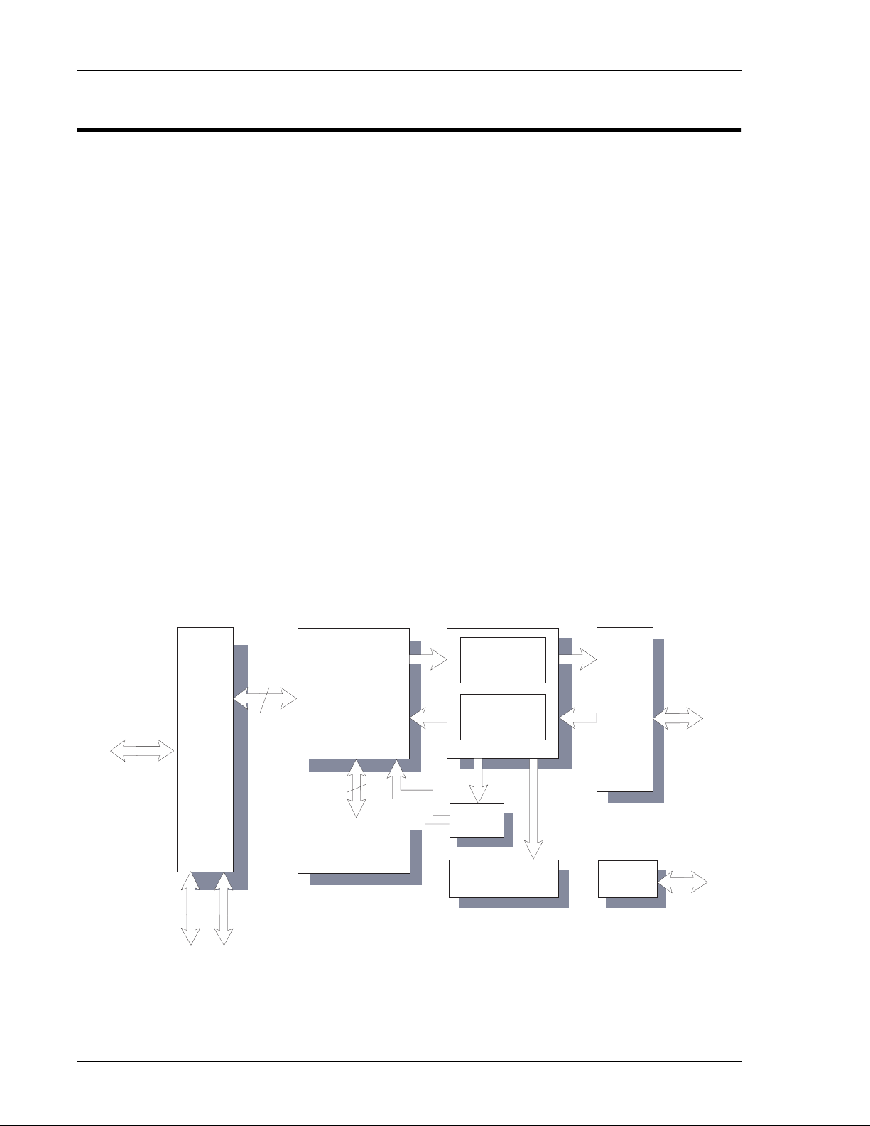
hundreds of Mbits. Figure 1 is a block diagram of the Gigabit Ethernet MAC.
Figure 1 The Gigabit Ethernet MAC Functional Block Diagram
EEPROM
FLASH
PCI I/F
LINK I/F
PACKET
FILTERS
RMON STATISTICS
MAC CORE
RX_MAC
(1000 Mbps)
PACKET FIFOs
DMA
ENGINE
TEST
JTAG
TX_MAC
(1000 Mbps)
GMII/MII/
TBI
PCI
CORE
(66 MHz)
Artisan Technology Group - Quality Instrumentation ... Guaranteed | (888) 88-SOURCE | www.artisantg.com

Overview
13
When the VMIPMC-6101 serves as a PCI target, the VMIPMC-6101 follows the PCI
configuration specification, and allows all accesses to the Gigabit Ethernet MAC to be
automatically mapped into free memory and I/O space upon initialization of the PCI
system.
When processing transmit and receive frames, the VMIPMC-6101 operates as master
on the PCI bus.
As a master, transaction burst length on the PCI bus is determined by several factors,
including:
• PCI latency timer expiration
• Type of bus transfer being made
• Size of the data transfer
• Whether the data is initiated by receive or transmit logic
Hardware Installation
The VMIPMC-6101 can be plugged into any PMC site that supports bus mastering.
The board will operate properly in either 32- or 64-bit sites. If the PMC site supports
triggering for the interrupts, use level triggering for the VMIPMC-6101 board. The
drivers available on the VMIC website allow for self-configuring of the board when
properly installed.
Media Connection
The VMIPMC-6101 is available with a copper interface using an RJ-45 front panel
connector. The copper interface connection is made using a Category 5 twisted-pair
cable for 1000BaseT or 100BaseTX. For 10BaseT, use Category 3, 4 or 5 twisted-pair
cables.
NOTE: If you want to use this adapter in a residential environment, you must use a
Category 5 twisted-pair cable.
Artisan Technology Group - Quality Instrumentation ... Guaranteed | (888) 88-SOURCE | www.artisantg.com

VMIPMC-6101 PMC-Based Copper Gigabit Ethernet Adapter
14
Reference Material List
Refer to PCI Local Bus Specification for a detailed explanation of the PCI Local bus.
The PCI Local bus Rev. 2.2 Specification is available from the following source:
PCI Special Interest Group
P.O. Box 14070
Portland, OR 97214
U.S.: (800) 433-5177
International: (503) 797-4207
FAX: (503) 234-6762
For a detailed explanation of the Common Mezzanine Card Family and its
characteristics, refer to the CMC Specification, P1386/Draft 2.0 from:
IEEE Standards Department
Copyrights and Permissions
445 Hoes Lanes, P.O. Box 1331
Piscataway, NJ 08855-1331, USA
For a detailed explanation of the Physical and Environmental Layers for PCI
Mezzanine Cards, refer to the PMC Specification, P1386.1/Draft 2.0 from:
IEEE Standards Department
Copyrights and Permissions
445 Hoes Lanes, P.O. Box 1331
Piscataway, NJ 08855-1331, USA
Physical Description and Specifications
Refer to Product Specification 800-756101-000 available from:
VMIC
12090 South Memorial Pkwy.
Huntsville, AL 35803-3308, USA
(256) 880-0444
(800) 322-3616
FAX: (256) 882-0859
www.vmic.com
Artisan Technology Group - Quality Instrumentation ... Guaranteed | (888) 88-SOURCE | www.artisantg.com

Overview
15
Safety Summary
The following general safety precautions must be observed during all phases of the
operation, service and repair of this product. Failure to comply with these precautions
or with specific warnings elsewhere in this manual violates safety standards of
design, manufacture and intended use of this product.
VMIC assumes no liability for the customer’s failure to comply with these
requirements.
Ground the System
To minimize shock hazard, the chassis and system cabinet must be connected to an
electrical ground. A three-conductor AC power cable should be used. The power
cable must either be plugged into an approved three-contact electrical outlet or used
with a three-contact to two-contact adapter with the grounding wire (green) firmly
connected to an electrical ground (safety ground) at the power outlet.
Do Not Operate in an Explosive Atmosphere
Do not operate the system in the presence of flammable gases or fumes. Operation of
any electrical system in such an environment constitutes a definite safety hazard.
Keep Away from Live Circuits
Operating personnel must not remove product covers. Component replacement and
internal adjustments must be made by qualified maintenance personnel. Do not
replace components with power cable connected. Under certain conditions,
dangerous voltages may exist even with the power cable removed. To avoid injuries,
always disconnect power and discharge circuits before touching them.
Do Not Service or Adjust Alone
Do not attempt internal service or adjustment unless another person, capable of
rendering first aid and resuscitation, is present.
Do Not Substitute Parts or Modify System
Because of the danger of introducing additional hazards, do not install substitute
parts or perform any unauthorized modification to the product. Return the product to
VMIC for service and repair to ensure that safety features are maintained.
Dangerous Procedure Warnings
Warnings, such as the example below, precede only potentially dangerous procedures
throughout this manual. Instructions contained in the warnings must be followed.
STOP: Dangerous voltages, capable of causing death, are present in this system. Use
extreme caution when handling, testing and adjusting.
Artisan Technology Group - Quality Instrumentation ... Guaranteed | (888) 88-SOURCE | www.artisantg.com

VMIPMC-6101 PMC-Based Copper Gigabit Ethernet Adapter
16
Safety Symbols Used in This Manual
Indicates dangerous voltage (terminals fed from the interior by voltage exceeding
1000 V are so marked).
Protective conductor terminal. For protection against electrical shock in case of a fault.
Used with field wiring terminals to indicate the terminal which must be connected to
ground before operating equipment.
Low-noise or noiseless, clean ground (earth) terminal. Used for a signal common, as
well as providing protection against electrical shock in case of a fault. Before
operating the equipment, terminal marked with this symbol must be connected to
ground in the manner described in the installation (operation) manual.
Frame or chassis terminal. A connection to the frame (chassis) of the equipment which
normally includes all exposed metal structures.
Alternating current (power line).
Direct current (power line).
Alternating or direct current (power line).
STOP: This symbol informs the operator that a practice or procedure should not be
performed. Actions could result in injury or death to personnel, or could result in
damage to or destruction of part or all of the system.
WARNING: This sign denotes a hazard. It calls attention to a procedure, a practice or
a condition, which, if not correctly performed or adhered to, could result in injury or
death to personnel.
CAUTION: This sign denotes a hazard. It calls attention to an operating procedure, a
practice or a condition, which, if not correctly performed or adhered to, could result in
damage to or destruction of part or all of the system.
NOTE: Calls attention to a procedure, a practice, a condition or the like, which is
essential to highlight.
OR
OR
Artisan Technology Group - Quality Instrumentation ... Guaranteed | (888) 88-SOURCE | www.artisantg.com

17
CHAPTER
Configuration and Installation
Contents
Unpacking Procedures . . . . . . . . . . . . . . . . . . . . . . . . . . . . . . . . . . . . . . . . . . . . . . . 18
Physical Installation. . . . . . . . . . . . . . . . . . . . . . . . . . . . . . . . . . . . . . . . . . . . . . . . . . 19
Cable Type and Installation . . . . . . . . . . . . . . . . . . . . . . . . . . . . . . . . . . . . . . . . . . . 21
Front Panel Status LEDs . . . . . . . . . . . . . . . . . . . . . . . . . . . . . . . . . . . . . . . . . . . . . . 23
Additional Setup and Configuration . . . . . . . . . . . . . . . . . . . . . . . . . . . . . . . . . . . 24
Troubleshooting . . . . . . . . . . . . . . . . . . . . . . . . . . . . . . . . . . . . . . . . . . . . . . . . . . . . . 25
PCI Configuration Troubleshooting . . . . . . . . . . . . . . . . . . . . . . . . . . . . . . . . . . . . 26
Common Problems and Solutions. . . . . . . . . . . . . . . . . . . . . . . . . . . . . . . . . . . . . . 27
Introduction
This chapter describes the installation and configuration of the board. Cable
configuration and board layout are illustrated in this chapter.
1
Artisan Technology Group - Quality Instrumentation ... Guaranteed | (888) 88-SOURCE | www.artisantg.com

18
1
VMIPMC-6101 PMC-Based Copper Gigabit Ethernet Adapter
Unpacking Procedures
CAUTION: Some of the components assembled on VMIC’s products may be sensitive
to electrostatic discharge and damage may occur on boards that are subjected to a
high-energy electrostatic field. When the board is placed on a bench for configuring,
etc., it is suggested that conductive material should be inserted under the board to
provide a conductive shunt. Unused boards should be stored in the same protective
boxes in which they were shipped.
Upon receipt, any precautions found in the shipping container should be observed.
All items should be carefully unpacked and thoroughly inspected for damage that
might have occurred during shipment. The board(s) should be checked for broken
components, damaged printed circuit board(s), heat damage, and other visible
contamination. All claims arising from shipping damage should be filed with the
carrier and a complete report sent to VMIC together with a request for advice
concerning the disposition of the damaged item(s).
System Requirements
Before installing the VMIPMC-6101 PMC-Based Ethernet Adapter, check your system
for the following required or minimum configuration requirements:
• One open 32- or 64-bit bus master PMC site
• 64 Mbyte of system memory
• The latest system BIOS for your computer
• Operating system; if using Microsoft Windows NT 4.0, service pack 5
• Copper interface using Category 5, twisted-pair cabling for 100/1000 Mbps
• An IEEE 802.3z or 802.3ab compliant gigabit switch or a buffered repeater
Software Drivers
Software drivers for the VMIPMC-6101 are available through the VMIC website (see
web address below). After downloading the driver of choice, go to the readme.txt file
for instructions to load the driver, or for Windows drivers, run the executable and
follow the on-screen instructions.
NOTE: The drivers must be installed before the VMIPMC-6101 can be used.
VMIC website: www.vmic.com
For drivers that are not available on the website, contact VMIC Customer Service.
VMIC Customer Service is available at: 1-800-240-7782.
Artisan Technology Group - Quality Instrumentation ... Guaranteed | (888) 88-SOURCE | www.artisantg.com
19
Physical Installation
1
Physical Installation
CAUTION: Do not install or remove the board while power is applied.
Host systems containing PMC card sites vary widely in appearance and board
installation procedures. VMIC recommends examining the host system installation
procedures prior to installing this board.
1. Remove the PMC slot cover bracket where the board is to be installed per the
host unit hardware documentation.
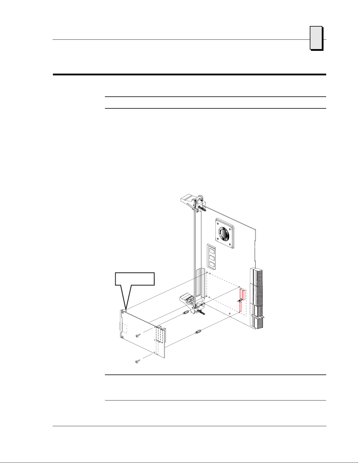
2. Insert this board firmly onto the PMC connectors (see Figure 1-1 for installation
of the VMIPMC-6101.)
3. Secure the VMIPMC-6101 board to the PMC connectors using the four screws
provided. See Figure 1-2 on page 20.
NOTE: The VMIPMC-6101 is designed to interface with any suitable PMC compliant
baseboard using a direct PCI bus interface compliant with v2.2 of the PCI signalling
specification as defined by IEEE P1386.1 Draft 2.0.
Figure 1-1 Installing the VMIPMC-6101
CompactPCI
Single Board CPU
VMIPMC-6101
Artisan Technology Group - Quality Instrumentation ... Guaranteed | (888) 88-SOURCE | www.artisantg.com
Table of contents
Other VMIC Adapter manuals


