Vocia WR-1 User manual

Biamp Systems, 9300 SW Gemini Drive, Beaverton, Oregon 97008 U.S.A. (503) 641-7287 www.biamp.com
Vocia®
WR-1
Operation Manual
January 2012

2
TABLE OF CONTENTS
VOCIA WALL REMOTE 1 (WR-1) FEATURES ..............................................3
FRONT VIEW ..................................................................................4-5
Setup and Use .................................................................................4
Display .......................................................................................4
Select Buttons .................................................................................4
Adjust Buttons.................................................................................4
Display Views .................................................................................4
Background Source Screen ......................................................................4
Volume Screen.................................................................................4
Volume Mute Screen ............................................................................5
Page Inhibit Screen .............................................................................5
Device Unavailable Screen.......................................................................5
Device Information Screen .......................................................................5
REAR VIEW....................................................................................6-7
Device ID .....................................................................................6
Network Connection ............................................................................6
SPECIFICATIONS & BLOCK DIAGRAM.....................................................8
WARRANTY .....................................................................................9
FCC COMPLIANCE............................................................................10
EC DECLARATION ............................................................................11
EU ROHS COMPLIANT .......................................................................12
3
VOCIA WALL REMOTE 1 (WR-1)
The WR-1 is a networked wall remote for use in a Vocia® system. It is designed to control background audio in user-congured music
zones. The WR-1 utilizes Power over Ethernet (PoE) technology. Once it is congured with Vocia® software interface, the WR-1 requires
nothing more than an Ethernet cable wired to a PoE-compliant network switch. The WR-1 allows the user to choose background music
input sources, paging inhibit and source mute from an attractive wall-mounted panel. A backlit liquid crystal display (LCD) facilitates naviga-
tion through the WR-1 menu. The WR-1’s esthetically pleasing design ts with most room decor.
FEATURES
• Wall mountable
• Power and data over a single Ethernet cable
• Backlit liquid crystal display (LCD)
• Software-congurable settings, including
volume, source selection, paging inhibit,
and mute source control
• Rotary switches for unit identication
• CE marked and RoHS compliant
• Covered by BIAMP Systems’ warranty
4
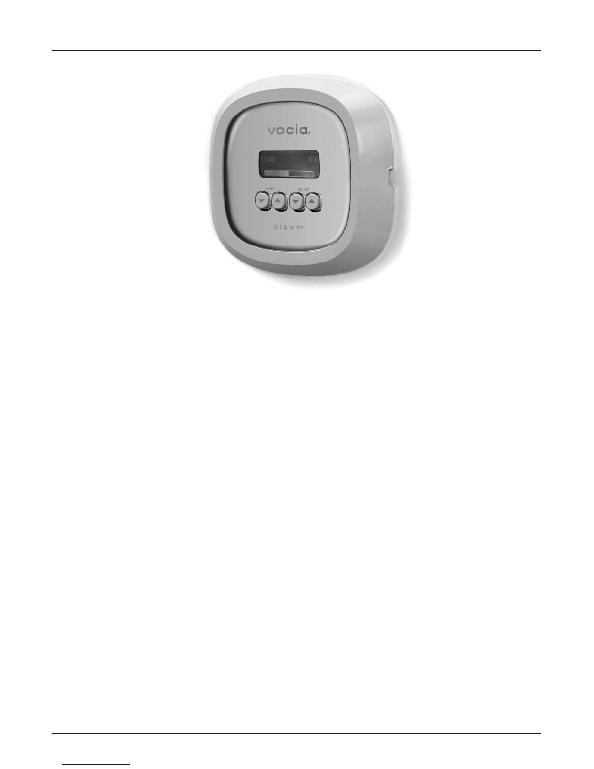
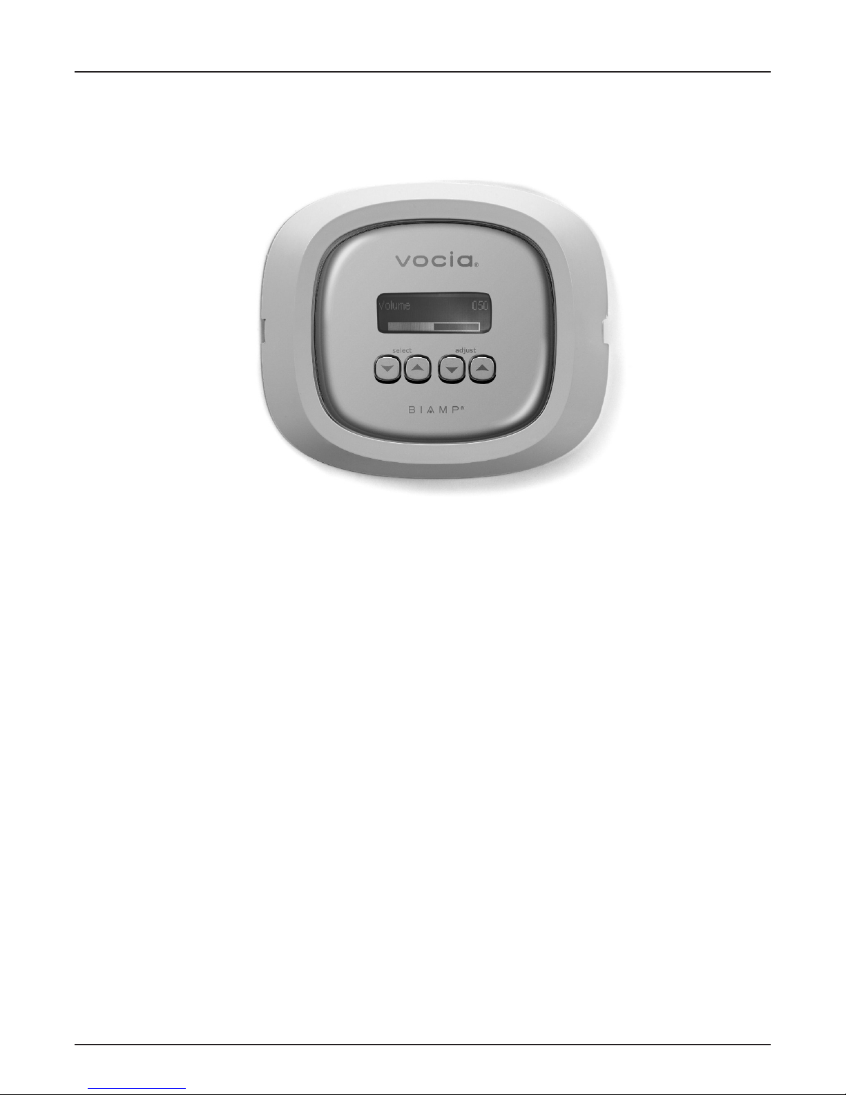
WR-1 FRONT VIEW
Setup and Use
The Vocia software provides an intuitive interface for conguration, DSP equalization, and programming of the WR-1. The information
supplied by this manual relates to physical connections and assignment. For more details on software setup, please consult the Vocia Help
File.Front Panel
Display
The WR-1 features a backlit display that provides the user with an easy-to-read interface to view the menu options and setup screen.
Please note: the display will ash during rmware updates. This behavior is normal.
Select Buttons
The two buttons below the Select label are used to choose different functions on the WR-1. The function of these buttons depends
on the image that is displayed on the screen.
Adjust Buttons
Below the Adjust label on the right side of the device are two buttons whose function depends on the image that is displayed on the screen.
Generally, the image will be the Volume Screen, so the Adjust + and - buttons will generally control the volume of the zone associated with
the WR-1. However, when the Page Inhibit Screen is displayed, for example, the buttons will turn this function on/off.
Display Views
The user can cycle through the screens listed below by pressing the select buttons:
Background Source Screen
This screen displays the current Source on the top line and the number of dened sources. A label associated with the currently selected
background source will be displayed below. If the user presses the adjust buttons while this screen is displayed, the currently displayed
audio source will be selected. If one or more local inputs are associated with the zone, they will be automatically added to the selection list.
Volume Screen
The Volume Screen is the default display screen, which the unit will revert to if a control has not been adjusted for a period of sixty seconds.
The LCD shows a number between 0 and 100 in the top right corner, and a bar graphic represents the volume setting. As volume increases,
the bar lengthens from left to right and the number increases. At maximum volume, the bar is at full length. At minimum volume, the bar is
replaced with the word Off.

5
WR-1 FRONT VIEW
Volume Mute Screen
This screen provides muting control for the current background source. The LCD shows Volume Mute at the top with On or Off displayed
in the lower center of the screen. When Volume Mute is on, the background source is muted and the current background volume setting
is stored. The volume setting will be restored when the mute is off.
Page Inhibit Screen
This screen will display Page Inhibit at the top with On or Off displayed in the lower center of the screen. If the user presses Adjust +, Page
Inhibit will be enabled (On). If the user presses Adjust -, Page Inhibit will be disabled (Off). When Page Inhibit is on, only Emergency Level
pages will reach the zone.
Device Unavailable Screen
The Device Unavailable Screen will become active if the WR-1 cannot connect to the Vocia system.
Device Information Screen
The Device Information Screen shows the Device ID, the system time, and the time and date of the last rmware update. To access the
Device Information Screen, press and hold three of the four front panel buttons.
Device ID System Time
Time/date of last
Firmware update
6
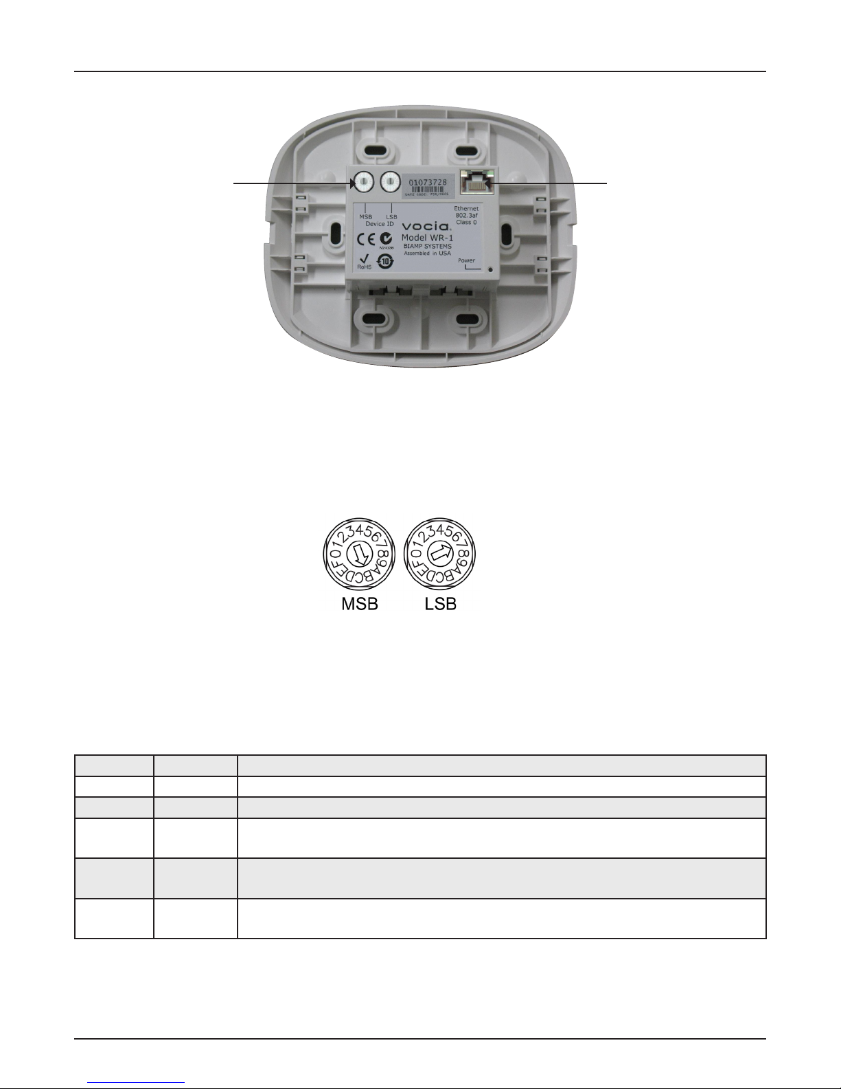
WR-1 REAR VIEW
Device ID
The rotary ID switches are located on the rear of the WR-1 and give the unit a unique Device ID. The switches are in hexadecimal format.
All WR-1 units must have a unique Device ID to function properly within a Vocia Paging World (i.e., it is not possible to have two WR-1 units
with the same Device ID of hex 07). To assign a Device ID of hex 07, turn the LSB switch to 7 and leave the MSB switch on 0. To create
an ID of hex B7, turn the LSB switch to 7 and turn the MSB switch to B. Device ID switches should be set using a 0.1 inch (2.5mm) to
0.12 inch (3.0mm) at blade screwdriver. More information on setting IDs and the hexadecimal numbering scheme used in Vocia can be
found in the Vocia Help File.
Please note: Changes made to the Device ID while connected to the network require a power cycle in order to take effect.
Network Connection
The WR-1 has one RJ45 connector that should be wired to shielded CAT5, CAT5e, CAT6, or CAT7 cable cabling to interface the WR-1
to a Vocia system via a PoE-compliant network switch. The RJ45 connector provides two LEDs that indicate Ethernet link and network activity
(see table below).
Left LED Right LED Description
None None No power or data connectivity. Please check the PoE network connection.
Green None Link established.
Green Flashing
amber
Link established and CobraNet activity detected; the unit is acting as a CobraNet performer.
Flashing
green
Flashing
amber
Link established and CobraNet activity detected; the unit is operating as a CobraNet conductor.
Flashing
amber
Flashing
amber
CobraNet fault. Check cabling and conguration for errors.
Network
Connection
Device ID

7
WR-1 REAR VIEW
This connection carries control data and power over CobraNet. PoE-enabled network switches or PoE midspan adapters must be used to
power the WR-1. These must be 802.3af compliant and must be isolated with respect to ground. The maximum distance between any unit
and an Ethernet switch is 100 meters (328 feet) when using copper cabling. Additional Ethernet switches and/or ber-optic cable can be
used to further extend distances between units on a network.
If other network trafc shares an Ethernet switch with the Vocia network, a managed switch should be used with separate VLANs.
The following diagrams illustrate valid network connections for the WR-1.
Ethernet switch
with PoE
Ethernet switch
without PoE
AC Power
PoE
injector

8
WR-1 SPECIFICATIONS
Wall Remote 1 SPECIFICATIONS
Connection: RJ45 with shielded Ethernet/PoE cable
(CAT5, CAT 5e, CAT6 or CAT7)
Dimensions:
Front:
Height:
Width:
Depth:
Within Wall
Height:
Width:
Depth:
6 inches (153mm)
5.1 inches (130mm)
.6 inches (15.4mm)
2.9 inches (73.5mm)
2.4 inches (60mm )
1.2 inches (30mm) (from front surface).
Power: 802.3af (PoE) Class 1
Ambient Operating
Temperature Range:
32-113 degrees F (0-45 degrees C)
Compliance: FCC Part 15, class B
CE marked
RoHS Directive
UL 60065 Listed, E215636
C-UL Listed, E215636
C-Tick, N24138 (Australia)
Weight 0.4 lbs. (0.18kg)
Wall Remote 1 BLOCK DIAGRAM
LCD
Keypad
ID Switches
Vocia System
control
PoE
Host
Processor

9
WR-1 WARRANTY
BIAMP SYSTEMS IS PLEASED TO EXTEND THE FOLLOWING 5-YEAR LIMITED WARRANTY TO THE ORIGINAL PURCHASER OF
THE PROFESSIONAL SOUND EQUIPMENT DESCRIBED IN THIS MANUAL
1. BIAMP Systems warrants to the original purchaser of new products that the product will be free from defects in material and
workmanship for a period of 5 YEARS from the date of purchase from an authorized BIAMP Systems dealer, subject to the
terms and conditions set forth below.
2 If you notify BIAMP during the warranty period that a BIAMP Systems product fails to comply with the warranty, BIAMP Systems
will repair or replace, at BIAMP Systems’ option, the nonconforming product. As a condition to receiving the benets of this warranty,
you must provide BIAMP Systems with documentation that establishes that you were the original purchaser of the products. Such
evidence may consist of your sales receipt from an authorized BIAMP Systems dealer. Transportation and insurance charges to
and from the BIAMP Systems factory for warranty service shall be your responsibility.
3. This warranty will be VOID if the serial number has been removed or defaced; or if the product has been altered, subjected to
damage, abuse or rental usage, repaired by any person not authorized by BIAMP Systems to make repairs; or installed in any
manner that does not comply with BIAMP Systems’ recommendations.
4. Electro-mechanical fans, electrolytic capacitors, gooseneck microphones, cords connecting handheld microphones, hard-drives,
displays, and normal wear and tear of items such as paint, knobs, handles, keypads and covers are not covered under this warranty.
All server-based devices are warranted for 3 years only.
5. This warranty is in lieu of all other warranties, expressed or implied. BIAMP Systems disclaims all other warranties, expressed or
implied, including, but not limited to, implied warranties of merchantability and tness for a particular purpose.
6. The remedies set forth herein shall be the purchaser’s sole and exclusive remedies with respect to any defective product.
7. No agent, employee, distributor or dealer of BIAMP Systems is authorized to modify this warranty or to make additional warranties on
behalf of BIAMP Systems. Statements, representations or warranties made by any dealer do not constitute warranties by BIAMP
Systems. BIAMP Systems shall not be responsible or liable for any statement, representation or warranty made by any dealer or
other person.
8. No action for breach of this warranty may be commenced more than one year after the expiration of this warranty.
9. Biamp systems shall not be liable for special, indirect, incidental, or consequential damages, including lost prots or loss of use
arising out of the purchase, sale, or use of the products, even if BIAMP Systems was advised of the possibility of such damages.
012012_585.0262.90B

10
FCC COMPLIANCE
FCC NOTICE - CLASS B DIGITAL DEVICE
NOTE: This equipment has been tested and found to comply with the limits for a Class B digital device,
pursuant to Part 15 of the FCC Rules. These limits are designed to provide reasonable protection against
harmful interference in a residential as well as in a commercial installation. This equipment generates, uses and
can radiate radio frequency energy and, if not installed and used in accordance with the instructions, may cause
harmful interference to radio communications. However, there is no guarantee that interference will not occur in a
particular installation If this equipment does cause harmful interference to radio or television reception, which can
be determined by turning the equipment off and on, the user is encouraged to try to correct the interference by
one or more of the following measures: 1) Reorient or relocate the receiving antenna, 2) Increase the separation
between the equipment and receiver, 3) Connect the equipment into an outlet on a circuit different from that to
which the receiver is connected or 4) Consult the dealer or an experienced radio/TV technician for help.

11
COMPLIANCE
! ! DoC VWR201003!
!
EC Declaration of Conformity
Biamp Systems Corporation, as manufacturer having sole responsibility, hereby
declares that the following described product complies with the applicable provisions of
the DIRECTIVES below except as noted herein. Any alterations to the product not
agreed upon and directed by Biamp Systems Corporation will invalidate this declaration.
Product Model: Vocia®WR-1
Product Description: Wall Remote for networking with audio DSPs
Applicable EC Directives: Applicable Harmonized Standards:
LVD Directive (2006/95/EC) Safety EN 60065:2002
EMC Directive (2004/108/EC) Emissions EN 55103-1:1996, Environment E2
Immunity EN 55103-2:1996
Special Considerations for Product Environment or Compliance:
Use only CE marked Power over Ethernet (PoE) device.
Shielded cabling must be used for system connections.
Technical Construction File, Location and Contact:
Biamp Systems Corporation phone: (503) 641.7287
9300 S.W. Gemini Drive fax: (503) 626.0281
Authorized Representative: Larry Copley, Compliance Engineer
Authorized Signature:
Issued: March 2010!
12
COMPLIANCE
EU RoHS COMPLIANT
This Biamp product, including all attendant cables and
accessories supplied by Biamp, meets all requirements of EU
Directives 2002/95/EC of January 27, 2003, and 2005/618/EC
of August 18, 2005, the EU RoHS Directives. An EU RoHS
Materials Content Declaration document may be obtained at
www.biamp.com
(This information is presented to comply with the requirements of Chinese law SJ/T11363-2006)”
bF}¢
Biamp Systems Corporation
©]*A (Remote Control Device)
Vocia WR-1
¢S
¬5
Pb
±
Hg
r
Cd
·
Cr+6
"´
PBB PBDE
Ad (Equipment Chassis)X O X O O O
(CD ROM) O O O O O O
U%8#¾^j (Manual and Paper Documents) O O O O O O
,8Tb,f_ (Box and Packing Materials) O O O O O O
0¡¬Tb=¢f_§bnbF}¢ SJ/T11363-2006 º*q.
X¡¬Hb=¢f_T6§bnbF}¢À SJ/T11363-2006 º*q.
<D8S¶·T6=¢f_·1#-4}63£¦ 0.01%kX 91/338/EECiZkX
76/769/EECº*µ98h.¼}¢8*+¬)Tl«»B
<SC}¢T6=¢f_±1#-4}63£¦ 0.1%:
1) E:$T6±
2) ±<°fa4®63¥ 0.35%
3) ±<³fa4®63¥ 0.4%
4) ±<²fa4®63¥ 4%
5) À|z{_±/±_4®±6£¦ 85%
6) E½¬$±
7) R{_T6±ª\¯8P@:,#
±6£¦ 80% 85%
8) ¿M¯ª\$±
9) G¤¸ORª{_
<mKQ&;~cº 10 Lga
• ~?wN 0-40C (32-104°F)
• xN 0-95%`(
• uWÀN 0-10,000 I
• ot2¹
• sbpS#v¨!¬
• y IEEE 802.3af PoE
• ¬sbY>Y>¬M/
• J0[e7V'f_¨Tb
Table of contents
Popular Remote Control manuals by other brands

RYAN SOUND LAB
RYAN SOUND LAB MusicPower Z302 Remote Volume Control user guide

MayTech
MayTech MTSKR1905WF user manual

Bricasti Design
Bricasti Design Bricasti M10 Owner's manual

Metronic
Metronic ZAP 3 manual

Crestron
Crestron TSR-310 Supplemental guide

Hearth and Home Technologies
Hearth and Home Technologies RCT-MLT-IV Installation and operating instructions


