Vogue P640STX Owner's manual


Content
Safety instruction.......................................................2
Product description.....................................................4
Installation.................................................................6
Specification.............................................................12
Maintenance and troubleshooting...............................16
Model nunbers list:
P640STX
P640STG
P750STG-1
P950STX
P950STG
P950STX-1
P950STG-1
NOTE: This User Instruction Manual contains important
information, including safety&installation points, which
will enable you to get the most out of your appliance.
Please keep it in a safe place so that it is easily available
for future reference; for you or any person not familiar with
the operation of the appliance.

This manual explains the proper installation and use of your appliance, please read it
carefully before using even if you are familiar with the product. The manual should be kept
in a safe place for future reference. In case of failure, only the Authorized Technical
Service may repair this hob. Otherwise the guarantee will be null and void.
Warning
General safety
l The appliance may only be installed and connected
by trained, Authorised persons.
l Built-in appliances may only be used af ter they have
built in to suitable built-in units and work surfaces
that meet standards.
l In the event of faults with the appliance or damage
to the glass toughened (cracks, scratches or splits),
the appliance must be switched off and
disconnected from the electrical supply, to prevent
the possibility of an electric shock.
l Repairs to the appliance must only be carried out by
trained Authorised persons.
l The technical and identification data for the hob
figure on the reference plate fixed to the appliance.
l This reference plate must be consulted before
making the electrical connections.
l The electrical connections must be made by
specialist aware to the legal and regulatory,
requirements in each country.
l If the cable is damaged in any way it must be
replaced by the manufacturer or after sale service
or by authorized technical staff, to avoid hazard.
Correct use
l People (including children) who, because of their
physical, sensory or mental capabilities or their
inexperience or ignorance are not able to use the
device safely, should not use this device without
supervision or instruction by a responsible person.
l This appliance should be used only for normal
domestic cooking and frying of food.
l The appliance must not be used as a work surface
or as a storage surface.
l Additions or modifications to the appliance are not
permitted.
l Do not place or store flammable liquids, highly
inflammable materials or fusible objects (e.g. plastic
film, plastic, aluminum) on or near the appliance.
l Do not heat an empty pan on the appliance.
Children’s safety
l The cooking zones will become hot when you
cook. Therefore, always keep small children
away from the appliance.
l The appliance is not intended for use by
young children or infirm persons without
supervision.
l Young children should be supervised to
ensure that they do not play with the
appliance.
Safety during use
l Remove stickers and film from the glass
ceramic.
l There is the risk of burns from the appliance if
used carelessly.
l Cables from electrical appliances must not
touch the hot surface of the appliance or hot
cookware.
l Overheated fats and oils can ignite very
quickly. Warning! Fire hazard!
l Switch the cooking zones off after each use.
l Users with implanted pacemakers should
keep their upper body at least 30 cm from
cooking zones that are switched on.
l Risk of burns! Do not place objects made of
metal, such as knives, forks, spoons and
saucepan lids on the cooking surface, as they
can get hot.
2
17
TROUBLESHOOTING
Servicing of the hotplates must only be done by an authorised service representative (see back of this booklet) and the
hotplate must not be modified. Power must be disconnected before any servicing or maintenance is conducted.
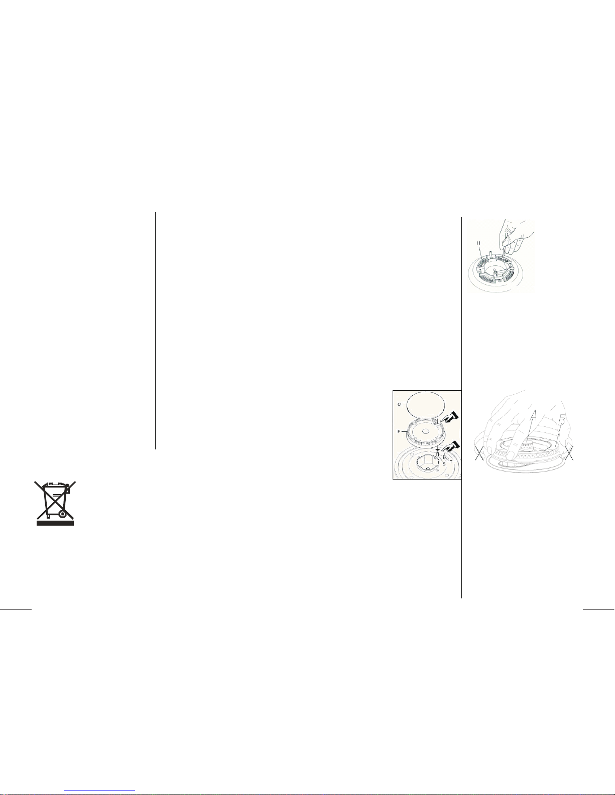
l Clean the panel: Suggest each clean after cooking
l Clean ignition needle ,thermocouple , burner and Pan support: Recommended cleaning at least once a month
Abnormal conditions include:
l Excessively yellow or sooting flame type.
l Flame lifting off the burner ports.
l Flame lighting back into the burner (normally associated with a popping sound).
l Objectionable odour of the flames combustion products.
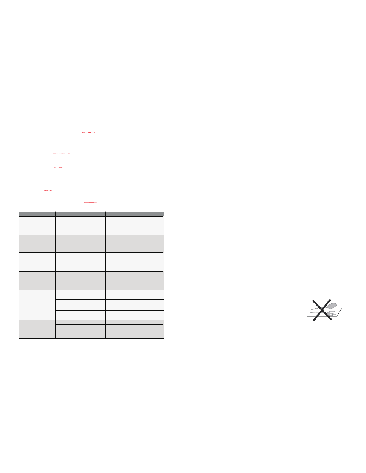
Should a faulty condition develop in the hotplate that is not described above, refer to the following table first for
possible causes and remedies prior to contacting an authorised service representative. Servicing beyond the remedies
listed shall only be undertaken by an authorised service representative.
FAULT POSSIBLE CAUSE REMEDY
No spark when gas control
knob depressed.
No power. Check plugged in and switched on.
Check mains circuit breaker.
Loose sparker cable. Call authorised representative.
Burner not aligned properly. Remove and re-fit burner.
Burner not lighting when
spark ignition working.
Gas supply off. Check gas supply valve on.
Burner not aligned properly. Remove and re-fit burner.
Burner ports blocked. Remove, clean and replace burner.
Burner goes out when
control knob released.
Flame safeguard not activated. Re-light, allow more time for flame safeguard
to activate.
Flame safeguard faulty connection or
broken. Call authorised representative.
Uneven flame pattern or
slight flame lifting. Burner ports blocked. Remove, clean and replace burner.
At minimum flame setting
the flame is too high. Turndown control setting incorrect. Call authorised representative.
Small flame on High
setting.
Regulator faulty. Call authorised representative.
Gas supply pressure low. Call authorised representative.
Incorrect injector fitted. Call authorised representative.
Blocked injector or gas supply tube. Call authorised representative.
Incorrect utensil size. Refer to operating instructions utensil
choice.
Flame too high on High
setting.
Regulator faulty. Call authorised representative.
Incorrect injector fitted. Call authorised representative.
Incorrect utensil size. Refer to operating instructions utensil
choice.

afety instructions
Safety when installation
l Do not use or store flammable materials in the
appliance storage drawer or near this appliance.
l Do not spray aerosols in the vicinity of this
appliance while it is in operation.
l For Universal LPG appliance:- Where this
appliance is installed in marine craft or caravans,
it shall not be used as a space heater.
l This hotplate must be installed in accordance
with:
AS 5601 - Gas Installations (for Australia)
NZS 5261 – Code of Practice for the Installation
of Gas Burning Appliances and Equipment (for
New Zealand)
Local gas fitting regulations
AS/NZS 3000 – Electrical Installations (Wiring
Rules)
Building codes
Any other relevant statutory regulations.
l Check the gas type label on the underside of the
hotplate, adjacent to the gas connection to
ensure it corresponds to the installation gas
supply. If in doubt contact the supply authority.
l The power supply cord (supplied) must not touch
against any hot surfaces and must be placed so
that its temperature does not exceed 75 degrees
at any point along its length.
l After connecting to gas, check for leaks using
soapy solution, never a naked flame.
l Where a flexible hose assembly is used, ensure
it is approved to AS/NZS 1869, Class B or D.
Any hose assembly used must be restrained
from accidental contact with the flue outlet of an
under bench oven. The hose is not to exceed
1.2m in length.
How to avoid damage to the appliance
l The glass toughened can be damaged by
objects falling onto it.
l The edge of the glass ceramic can be damaged
by being knocked by the cookware.
l Cookware made of cast iron, cast aluminum or
with damaged bottoms can scratch the glass
toughened if pushed across the surface.
l Objects that melt and things that boil over can
burn onto the glass ceramic and should be
removed straightaway.
l Do not use the cooking zones with empty
cookware or without cookware.
l To avoid damaging cookware and glass
ceramics, do not allow empty saucepans or
frying pans to keep heating by the hob.
l The ventilation gap of 5mm between the worktop
and front of the unit underneath it must not be
covered.
l Do not modify this appliance.
Safety when cleaning
l For cleaning, the appliance must be switched off
and cooled down.
l For safety reasons, the cleaning of the appliance
with steam jet or high pressure cleaning
equipment is not permitted.
Disposing of the device
When disposing of the device, do not bring it to regular municipal waste
containers. Instead, bring it to electrical and electronic waste recycling
and reuse center. A relevant label has been put on the device, its instructions
manual, or the package. The device has been manufactured of recyclable
material. By bringing old device to recycling collection center, you show
that you care about nature. Ask your local environment care authority for
information on location of such facilities.
16
3
Cleaning and maintenance should be carried out with
the appliance cold especially when cleaning the
enameled parts. Avoid leaving alkaline or acid
substances(lemon juice, vinegar etc.) on the surfaces.
STAINLESS STEEL
The stainless steel hob of the hotplate must be
cleaned regularly (e.g. weekly) to ensure long
life expectancy of the hotplate.
Ensure hotplate has cooled. Wash down with warm
soapy water and rinse with clean water.
Dry with a clean soft cloth. A specialized stainless
steel cleaning fluid may be used.
NOTE: Ensure that wiping is done along with the
grain of the stainless steel to prevent any unsightly
crisscross scratching patterns from appearing.
TRIVETS (UTENSIL SUPPORTS)
Enameled parts must only be washed with a sponge
and soapy water or with non-abrasive products. Rinse
with clean water. Dry with a clean soft cloth.
BURNERS
Remove trivets from
hob. Ensure burners
are cool. Remove the
burners enameled
cap (C) and aluminum
burner crown (F).
Wash down with
warm soapy water
and rinse with clean
water. Dry with a
clean soft cloth.
Use a cotton bud, tooth brush, or some other item to
clean out any incrustations or dirt from the four holes
marked(H)
Replace burners and ensure they are correctly
repositioned over the igniter (S) and thermocouple (T).
The igniter (S) must be clean for trouble free sparking.
Test burner ignition and burner flame for correct
operation.
The Triple Ring (Wok) burner (diagrams below) does
not fit over the igniter or thermocouple but must be
placed on its supports. If burner is placed correctly it
will not rotate on its supports.

duct description
Model No.
P640STX
P640STG
P750STG-1
P950STX
P950STG
P950STX-1
P950STG-1
1:Top plant
2:pan support
3: Wok Burners
4: Rapid Burners
5: Semi-rapid
Burners
6: Auxiliary Burners
7:Knob
15 4
Accessory Name Quantity
User Manual 1
Adhesive sealing tape 1
LPG nozzle 1set
LPG label 1set
Screws ST4.2X24 4
Securing brackets 2
Do not place anything, eg.flame tamer, asbestos mat, between pan
and pan support as serious damage to the appliance may result.
Do not remove the pan support and enclose the burner with a wok
stand as this will concentrate and deflect heat onto the hotplate.
Do not use large pots or heavy weights which can bend the pan
support or deflect flame onto the hotplate.
Locate pan centrally over the burner so that it is stable and does not
overhang the appliance.
Use only a wok support supplied or recommended by the
manufacture of the appliance.
NOTE: Enclosure may be circular or square

5
Technical Specifications
Details of the methods of connection
Model
product
dimensions
(h x w x d) mm
Cut-out
Size
( w x d)mm
App’x net
weight
Electrical connection Rated
input
power
P640STX 118x600x520 560x480 11.5 Kgs 220-240V/50-60Hz 2W
P640STG 116x610x520 560x480 14.0 Kgs 220-240V/50-60Hz 2W
P750STG-1 116x760x520 690x480 17.0 Kgs 220-240V/50-60Hz 2W
P950STX 118x870x520 840x480 15.4 Kgs 220-240V/50-60Hz 2W
P950STG 116x890x520 840x480 18.8 Kgs 220-240V/50-60Hz 2W
P950STX-1 118x870x520 840x480 15.4 Kgs 220-240V/50-60Hz 2W
P950STG-1 116x890x520 840x480 18.8 Kgs 220-240V/50-60Hz 2W
G1/2〃
14
The hotplates are fitted with mains powered electronic spark ignitors, so must be connected to mains power
supply (i.e. nominal 220 - 240 V ac) to operate. If power is not available, the hotplate will still work but the burners
will have to be lit with a match or similar.
Depressing the gas control knob of any burner will activate the spark ignition for all burners. To light the burner,
turn the gas control knob to the High Flame setting of the burner to be lit, while at the same time depressing the
gas control knob to activate the spark ignition.
Once the burner is alight continue to depress the gas control knob for 5 – 10 seconds to allow the flame
safeguard to activate. If when you release the gas control knob, the burner flame goes out the flame safeguard
has not heated up enough so repeat the ignition procedure after waiting 1 minute for gas to disperse. If problems
with burner lighting persist, refer to the TROUBLESHOOTING section of these instructions.
If power is not available, light a match or similar, then turn the gas control knob for the burner to be lit, to the
High Flame setting. Once again if problems with burner lighting persist, refer to the TROUBLESHOOTING
section of these instructions.
When burner lights, adjust desired flame height. On finishing, turn control knob to off position marked with a
black DOT.
BURNER AND UTENSIL CHOICE
The maximum utensil (pan) diameters in millimetres
(mm) for each burner are:
For Natural Gas and Universal LPG hotplates
Auxiliary=160mm
Semi-Rapid= 200mm
Rapid = 220 mm
Wok) = 260 mm
The minimum utensil (pan) diameters in millimetres
(mm) for each burner are:
Auxiliary = 80 mm
and Semi-Rapid = 120 mm
Rapid =180mm
Wok = 220mm
For best efficiency and to ensure utensil handle does
not overheat, place the utensil centrally on the burner
and adjust the flame height so all the flame remains
under the utensil.

Installation
Before installation:
l Before cutting into any bench tops, ensure the minimum clearances to walls, adjacent
surfaces and overhead surfaces required by the relevant gas appliance installation code
(see above) will comply. Dimensions are specified in millimeters (mm)
Overhead cupboards and range hood = 650 mm.
Side and rear clearance = 200 mm to any burner edge.
Overhead exhaust/ceiling fan = 750 mm
Horizontal surfaces adjacent the hob = less than or equal to the hob height.
Ensure there is sufficient clearance to fit the regulator and/or flexible hose connection with
the hotplate in the installed position.
When you have installed the hob, make sure that
l The GPO(general purpose outlet) must always be in an accessible position.
l The supply connection point, test point and natural gas regulator adjustment screw (for
Natural gas installation) are accessible for testing and/or adjustment with the hotplate in
the installed position.
1. Cupboard Cutting
Bench top thickness, 30– 40 mm (3 – 4 cm).
TO BE INSTALLED ONLY BY AN AUTHORIZED PERSON.
P640STX/P640STG P950STX/P950STG/
P950STX-1/P950STG-1
P750STG-1
13 6
Description Explanation
Zone indicators
These show which zone is under control.
Flame power
Flame power of the zones, is the lowest and is the
highest.

12
2. Place burner box
Apply the adhesive sealing tape to the underside lip of the burner box. Shown at G opposite.
Place burner box into cutout hole and fit clamping brackets to clamp the hotplate to the bench.
3. Fit burners and trivet.
Replace burners and ensure they are correctly repositioned over the ignitor (S) and
thermocouple (T). The ignitor (S) must be clean for trouble free sparking. Test burner ignition
and burner flame for correct operation, If burner is placed correctly it will not rotate on its
supports..
The Triple Ring burner (diagrams below) does not fit over the igniter or thermocouple but must
be placed on its supports.
7
Burners
Type
Universal LPG
2.75kPa Model
Injector
Dia(mm)
Nominal Gas
Consumption
P640STX P640STG P950STX P950STG P750STG-1 P950STX-1 P950STG-1
SS TG SS TG TG SS TG
Auxiliary 0.52 3.0MJ/h 1 1 1 1 1 1 1
Semi rapid 0.72 6.3MJ/h 2 2 2 2 2 2 2
Rapid 0.88 10.0MJ/h 0 0 1 1 1 1 1
Wok 0.50+2-0.60 12.3MJ/h 1 1 1 1 1 1 1
TOTAL NHGC(MJ/h)27.9 27.9 37.9 37.9 37.9 37.9 37.9
Burners
Type
NATURAL GAS
1.0kPa Model
Injector
Dia(mm)
Nominal Gas
Consumption
P640STX P640STG P950STX P950STG P750STG-1 P950STX-1 P950STG-1
SS TG SS TG TG SS TG
Auxiliary 0.90 3.6MJ/h 1 1 1 1 1 1 1
Semi rapid 1.18 6.3MJ/h 2 2 2 2 2 2 2
Rapid 1.50 10.0MJ/h 0 0 1 1 1 1 1
Wok 0.70+2-1.05 12.5MJ/h 1 1 1 1 1 1 1
TOTAL NHGC(MJ/h)28.7 28.7 38.7 38.7 38.7 38.7 38.7
Note:
For panel: TG=toughened glass; SS= Stainless Steel;
Depending on the hotplate model, the burner choices are:
P640STX,P640STG: Auxiliary, Semi-Rapid x2, and Wok burners.
P750STG-1,P950STX,P950STG,P950STX-1,P950STG-1: Auxiliary, Semi-Rapid x2, Rapid
and Wok burners.

11
Wiring diagra m for P950STX/P950STX-1
P950STG/P950STG-1/P750STG-1
8
3. Electrical connection.
Install a 10 amp general purpose outlet (GPO) in accordance with relevant electrical standards
and/or codes of practice applicable.
The power supply cord (supplied) must not touch against any hot surfaces and must be placed
so that its temperature does not exceed 75℃at any point along its length.
After having installed the hotplate, the GPO must always be in an accessible position.
Wiring diagram for P640STX/P640STG
4. Gas connection
Install in accordance with relevant gas standards and/or codes of practice applicable.
Connect the elbow fitting to the appliance gas manifold connection, and check that seals
between the elbow
and manifold connection are in place and in good condition.
l For Natural gas: connect the natural gas appliance regulator (pictured opposite) with
integral test point using approved gas thread tape or compound to the
elbow fitting.
l For Universal LPG: connect the brass test point adaptor (pictured opposite)
using approved gas thread tape or compound to the elbow fitting.
Ensure the supply connection point, test point and natural gas regulator
adjustment screw (for Natural gas installation) are accessible for testing and/or
adjustment with the hotplate in the installed position.
Where a flexible hose assembly is used, ensure it is approved to AS/NZS 1869,
Class B or D with max. length of 1.2 metres. Any hose assembly used must be
restrained from accidental contact with the flue outlet of an under bench oven.
This hose assembly shall be suitable for connection to a fixed consumer piping
outlet located as follows:
Gas Conversion (NG -ULPG)
If the required gas conversion kit is not supplied with your appliance, Gas Conversion
shall only be undertaken by authorized persons.
The NG to LPG conversion kit contains
-Test point adapter -ULPG Gas Type label
-Auxiliary Jet φ0.52mm -Semi-Rapid Jet φ0.72mm
- Rapid Jet φ0.88mm -Wok Jetφ0.50mm(IN)+ φ0.60mm(OUT)X2
Converting to a different gas type
When Converting from NG to ULPG ensure that the NG regulator is removed and
replaced with the Test Point Assembly supplied in this kit. An AGA Approved
gasregulator suitable for a supply pressure of 2.75 kPa should be part of the gas tank
supply and the test point pressure must be adjusted to 2.75 kPa.
Changing the jets
1. Remove pan supports, burner heads and cups.
2. Use a size 7 socket wrench to unscrew and remove the jets,
replacing them with those supplied in this kit. Ensure you
use the correct jet for the corresponding burner.
3. Fit the Gas type label supplied with this kit next to the gas
connection point and remove the existing label.
Setting the minimum level
1. Remove Panels, knobs and water dish.
2. Reassemble the burner heads, caps and knobs.
3. Light one of the burners and turn the tap to minimum flame.
4. Use a thin blade screwdriver to turn the by-pass screw located on the
right of the brass shaft as shown right. Turn the by-pass screw fully
clockwise. The result should be a small, stable flame which
is uniform around the entire burner ring. If not, turn the by-pass
screw anti-clockwise until satisfied with the flame.
5. Check that the burner does not go out when the tap is turned
quickly from the maximum to the minimum position.
6. Repeat for each burner.
7. Remove the burner heads, caps and knobs.
8. Reassemble Panels, burner heads, caps, knobs and pan supports.

10
Hotplates at a point 800 mm to 850 mm above the floor and in the region outside the width of
the appliance to a distance of 250 mm.
Inlet connection region for flexible hose
After connecting to gas, check for leaks using soapy solution, never a naked flame.
Fit the duplicate data plate (supplied in separate bag) on a surface adjacent to the hotplate, for
example, the inside of the cupboard door so it is clearly visible for any service technician.
SETTING THE GAS PRESSURE:
Fit a manometer with a 6 mm rubber hose to the test point on the regulator (for natural gas).
For the Model P640STX, P640STG, P750STG-1, P950STX, P950STG, P950STX-1,
P950STG-1 , light Triple Ring and Auxiliary burner on and adjust test point pressure to 1.00
kPa. Turn the two burners off and on again and recheck the pressure is same as set previously
or adjust as required.
For all the other models, light all burners on and adjust test point pressure to 1.00 kPa. Turn
burners off and on again and recheck the pressure is same as set previously or adjust as
required.
TEST FOR CORRECT OPERATION:
After installation and test point setting, each burner ignition and operation must be tested
individually and with all burners operating. This testing must be done by the installer before
leaving.
ADJUSTING THE BURNER MINIMUM FLAME HEIGHT:
NOTE: This adjustment can only be performed by authorised service personnel.
The minimum burner flame is factory adjusted for the gas type stated on the gas type label
adjacent to the gas connection and should not require adjustment. Adjustment may be
required if the hotplate has been converted from Natural gas to Universal LPG or vice versa.
GAS CONVERSION INSTRUCTIONS:
The manufacturers servicing instructions detail how authorised personnel may convert the
hotplate from Natural gas to Universal LPG or from Universal LPG to Natural gas. Contact the
manuf acturer or agent as required.
9
Gas Conversion (ULPG -NG)
If the required gas conversion kit is not supplied with your appliance, Gas Conversion
shall only be undertaken by authorized persons.
The ULPG to NG conversion kit contains
-NG Regulator -NG Gas Type label
-Auxiliary Jet φ0.9mm -Semi-Rapid Jet φ1.18mm
- Rapid Jet φ1.5mm -Wok Jetφ0.70mm(IN)+ φ1.05mm(OUT)X2
Converting to a different gas type
When Converting from ULPG to NG ensure that the ULPG test point is removed and
replaced with the AGA Approved NG Regulator supplied in this kit. The test point
pressure must be adjusted to 1.00kPa with the largest burner operating on maximum
flame.
Changing the jets
1. Remove pan supports, burner heads and cups.
2. Use a size 7 socket wrench to unscrew and remove the jets,
replacing them with those supplied in this kit. Ensure you
use the correct jet for the corresponding burner.
3. Fit the Gas type label supplied withthis kit next to the gas
connection point and remove the existing label.
Setting the minimum level
1. Remove Panels, knobs and water dish.
2. Reassemble the burner heads, caps and knobs.
3. Light one of the burners and turn the tap to minimumflame.
4. Use a thin blade screwdriver to turn the by-pass screw located on the
right of the brass shaft as shown right. Turn the by-pass screw fully
counterclockwise. The result should be a small, stable flame which
is uniform around the entire burner ring. If not, turn the by-pass
screw anti-clockwise until satisfied with the flame.
5. Check that the burner does not go out when the tap is turned
quickly from the maximum to the minimum position.
6. Repeat for each burner.
7. Remove the burner heads, caps and knobs.
8. Reassemble Panels, burner heads, caps, knobs and pan supports.
This manual suits for next models
6
Table of contents
Other Vogue Hob manuals
Popular Hob manuals by other brands

Kleenmaid
Kleenmaid CH 600 CE Instructions for installing and using

Robam
Robam JZT-B291 Use manual

Zanussi
Zanussi ZAF20 Instructions for use

ROSIERES
ROSIERES RBI6475T Instructions for use and installation

CDA
CDA HE6051FR Installation, use and maintenance

Candy
Candy Trio 503/1 Instructions for use and installation

Technika
Technika TGC6GSS Instructions for use and installation

ROSIERES
ROSIERES RVM 324 Instructions for use and installation

Electrolux
Electrolux EHG 7763 Instruction booklet

BOMANN
BOMANN EBK 964 instruction manual

Indesit
Indesit VIA320XSC Instructions for use

Signature Kitchen Suite
Signature Kitchen Suite SKSRT480SIS owner's manual