Blackline Safety G7 EXO User manual

Technical User Manual
G7 EXO


1 OVERVIEW..............................................................................................1
1.1 G7 EXO........................................................................................................1
1.2 Blackline Safety Network..................................................................1
1.3 Blackline Live web portal .................................................................1
1.4 Gas inlet modules.................................................................................2
1.5 Connection modules..........................................................................2
1.6 In the box..................................................................................................3
1.7 Hardware details ...................................................................................3
2 SETUP...........................................................................................................6
2.1 Placement.................................................................................................6
2.2 Location.....................................................................................................6
2.3 Mounting ..................................................................................................6
2.4 Setup wizard............................................................................................7
2.5 Connectivity light.................................................................................7
3 USER INTERFACE .........................................................................9
3.1 Buttons ...................................................................................................... 9
3.2 Screen overview................................................................................... 9
3.3 Battery...................................................................................................... 11
3.4 Power on/o ........................................................................................12
3.5 Maintenance code............................................................................13
3.6 Alarm test...............................................................................................13
3.7 Siren and Speaker..............................................................................14
4 SAFETY ALERTS AND ALARMS.............................. 15
4.1 Yellow warning alarm......................................................................15
4.2 Red alert..................................................................................................15
4.3 LiveResponse.......................................................................................16
5 SAFETY FEATURES....................................................................17
5.1 Functional settings ........................................................................... 17
5.2 Gas sensor settings...........................................................................18
6 COMMUNICATION..................................................................19
6.1 Two-way messaging.........................................................................19
6.2 Two-way voice calls..........................................................................19
6.3 Push-to-talk (PTT)..............................................................................20
7 GAS DETECTION .......................................................................21
7.1 Bump test............................................................................................... 21
7.2 Calibration .............................................................................................22
7.3 Zeroing sensors...................................................................................23
7.4 LEL sensor precautions...................................................................24
7.5 PID target gases..................................................................................24
8 CARTRIDGES.................................................................................... 25
8.1 Cartridge options...............................................................................25
8.2 Changing cartridges ........................................................................25
8.3 Cartridge care......................................................................................26
8.4 Sensors in cold weather.................................................................26
9 GAS INLETS ...................................................................................... 26
9.1 Manual calibration inlet .................................................................26
9.2 Pump inlets...........................................................................................26
10 ELECTRICAL PORTS................................................................27
10.1 Power port.............................................................................................27
10.2 A/B interface ports............................................................................28
11 FIRMWARE UPDATES...........................................................30
11.1 Over-the-air (OTA) updates..........................................................30
11.2 Firmware update kits.......................................................................30
12 SUPPORT..............................................................................................30
12.1 Learn more............................................................................................30
12.2 Customer Care.....................................................................................30
13 SPECIFICATIONS ........................................................................31
13.1 Detailed specications ................................................................... 31
14 LEGAL NOTICES AND CERTIFICATIONS..... 33
14.1 Legal notices ........................................................................................33
14.2 Intrinsically safe certication.......................................................34
CONTENTS


G7 EXOTECHNICAL USER MANUAL || 1
1. OVERVIEW
1.1 G7 EXO
Cloud-Connected Area Monitor
G7 EXO is a cloud-connected area monitor that bundles industry-
leading gas detection with automated compliance and business
analytics tools. For the rst time ever, the days of manually collecting
data from the eld, reviewing spreadsheets and compiling reports are
behind you.
G7 EXO solves the challenges of continuous toxic and combustible gas
monitoring for sites, facilities and fence lines. Automating long-term
area monitoring and connected safety for streamlined eciency, G7
EXO allows teams to focus on their work at hand.
In the event of a safety incident or gas exposure, monitoring personnel
can see what has happened and communicate with workers directly via
text messaging or an optional two-way voice calling feature through
their EXO.
1.2 BLACKLINE SAFETY CLOUD
The Blackline Safety Cloud is a cloud-hosted system consisting of
cellular networks, satellite networks, the Blackline Live™ web portal
application, your monitoring account and G7 EXO.
EXO comes with basic system access which allows EXO to connect to
the Blackline Safety Cloud. Depending on your needs and requirements,
additional service plan options are available including 24/7 safety
monitoring by Blackline’s Safety Operations Center and two-way voice
communication.
1.3 BLACKLINE LIVE WEB PORTAL
The cloud-hosted Blackline Live web portal monitors and manages
all of your workers and G7 devices, and delivers reports and business
analytics insights.
Blackline Live
Blackline Live’s real-time alerting and live map allows you to quickly
locate and respond to gas events and other incidents in the eld.
You can use Blackline Live to create and customize conguration
proles that determine how a device or a group of devices operates in
the eld. Similarly, alert proles are set up to determine what contacts
should be notied in the event of an incident and what response
protocol monitoring personnel will follow to ensure your team gets the
help it needs.
Blackline Live keeps track of alert history and gas sensor calibrations
and bump tests, eliminating the need to manually retrieve data logs
from the eld.
Lastly, Blackline Live allows you to tailor user access depending on
employee roles: employee, supervisor, administrator and monitoring
team. This ensures that everyone has access to the right tools to
accommodate their role in a comprehensive monitoring program.
For more information about Blackline Live visit
support.blacklinesafety.com/products/blackline-live.
Blackline Analytics
With Blackline Analytics you can review data collected from your
EXO eet to make decisions follow up with your team and ensure
everything is running smoothly. Choose from a number of dierent
reports and lters to explore your data.
Blackline Analytics is built directly into the Blackline Live portal,
allowing employees with the appropriate user access controls to
see your organization’s data. If users have only been given access to
specific groups of devices, they will only see data attached to those
particular devices.
For more information about Blackline Analytics visit
support.blacklinesafety.com/products/blackline-analytics.
2|| G7 EXO TECHNICAL USER MANUAL
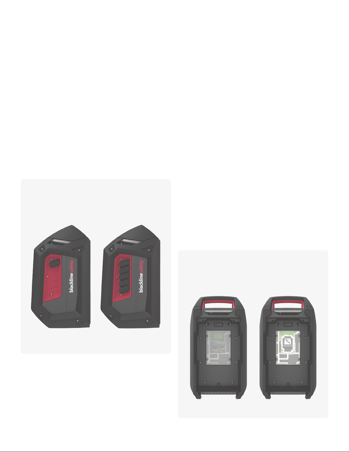
1.4 GAS INLET MODULES
What is a gas inlet module?
Gas inlets enable calibration, bump tests and air sampling from remote
areas. Gas inlet modules allow you to change EXO’s gas inlets to better
suit your area monitoring needs. Gas inlet modules are always tted with
one diusion gas inlet and may also include up to 4 pump gas inlets.
Diusion module
This module has a manual calibration inlet that requires a fixed flow
regulator to function correctly.
Four-channel pump module
This module has a manual calibration inlet that requires a xed ow
regulator to function correctly. It also has four pump inlets that can
sample air from remote areas using internal pumps and external tubes.
1.5 CONNECTION MODULES
What is a connection module?
A connection module links EXO to the Blackline Safety Cloud using a
cellular network or the iridium satellite network.
EXO will rst try to connect to the Blackline Safety Cloud with the built
in cellular connection module. If cellular coverage is not available and
an optional satellite connection module is installed, EXO will try to
connect to the Blackline Safety Network through the iridium satellite
network. See sections 2.5 and 3.2 for more information on connectivity.
Cellular connection module
This module works with 2G/4G networks in Europe, and 3G/4G
networks in North America to connect EXO to the Blackline Safety
Network. Cellular series are available in over 100 countries, supporting
over 200 cellular networks. This module is built into every EXO.
Satellite connection module
When EXO is not in cellular coverage, this module works with the
iridium satellite network to connect EXO to the Blackline Safety Cloud.
In the future, this module can be pre-installed in EXO. It can also be
purchased as an upgrade for EXOs in the eld and will need to be
installed by a trained technician.
NOTE: Two-way voice capabilities and push-to-talk are not available
when connected via satellite.
InstalledNot installed
Is a satellite connection module currently installed in EXO?
If you are unsure if EXO has a satellite connection module installed,
refer to the window behind the battery pack. You can also nd this
information in the main menu under Advanced > Comm info.
Four-channel pump
module installed
Diusion module
installed
What gas inlet module is currently installed in EXO?
EXO can have one of two gas inlet modules installed, the
diusion module or the four-channel pump module. If you are
unsure of which module is installed, refer to the intake side of EXO.
G7 EXOTECHNICAL USER MANUAL || 3
1.6 IN THE BOX
G7 EXO comes with the following components:
G7 EXO safety and area gas monitor
This technical user manual
1m (3ft) of tubing tted with a quick connect coupling insert
Quick charger with battery pack hex key
Pre-installed multi-gas cartridge
Pre-installed cellular connection module
Pre-installed gas inlet module (one of two)
Optional pre-installed satellite connection module
Certication and support card
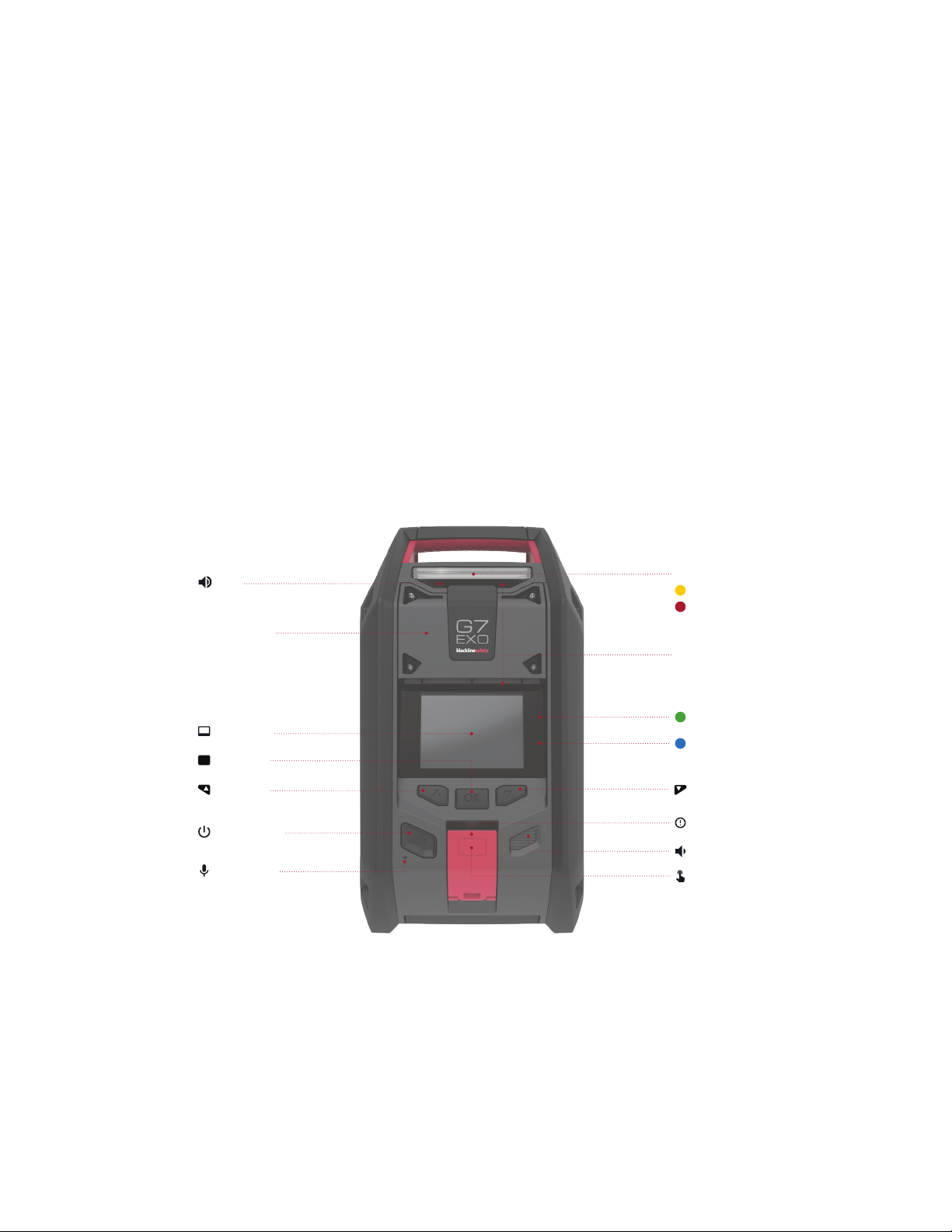
1.7 HARDWARE DETAILS
FRONT
Cartridge cover
360° Air diusion vents
Connectivity light
Warning alarms
Alerts
Top light
LiveResponse light
Power button
Microphone
OK button
OK
LCD screen
Speaker
SOS latch pull
PTT latch push
Down buttonUp button
Siren
4|| G7 EXO TECHNICAL USER MANUAL
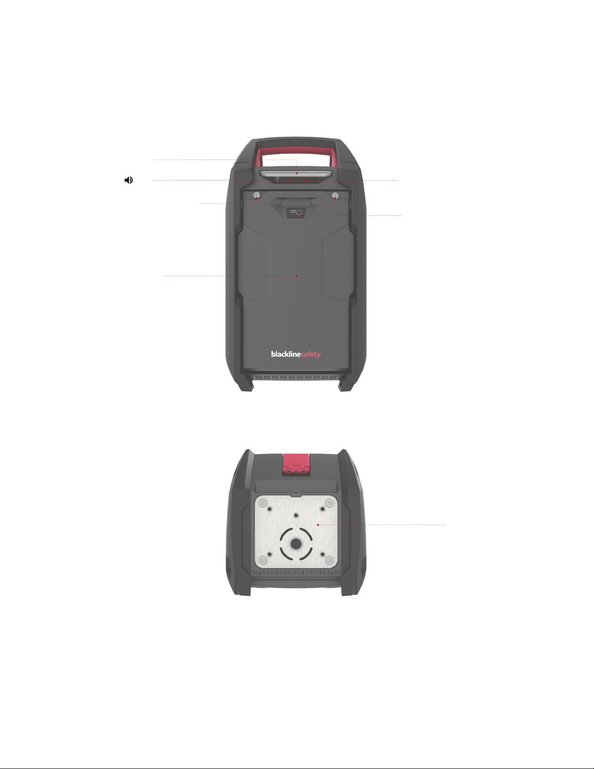
BACK
Top light
Battery retention screws
360° Air diusion vent
Battery power gauge
Battery pack
BOTTOM
Mounting plate
Siren
G7 EXOTECHNICAL USER MANUAL || 5
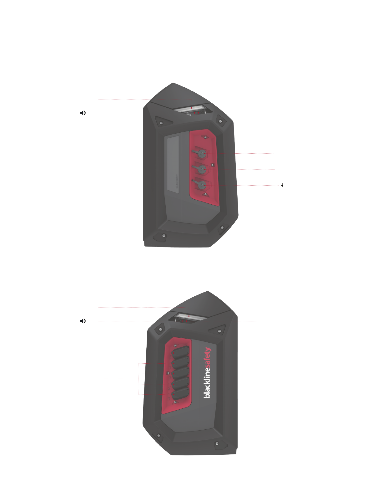
Interface port B
Interface port A
RIGHT SIDE
LEFT SIDE
Manual calibration inlet
Pump inlets
(Optional)
Power port
360° Air diusion vent
360° Air diusion vent
Top light
Siren
Top light
Siren

6|| G7 EXO TECHNICAL USER MANUAL
2. SETUP
2.1 PLACEMENT
EXO performs best when placed strategically within the area you wish
to monitor. When placing EXO keep the following in mind:
Positioning
Keep EXO upright
Keep EXO accessible for regular interactions like bump tests
and messages
Do not hang EXO by its handle
Environmental
Keep EXO electrical ports and gas inlets covered when not in use
Do not place EXO in water
Consider wind direction and air ow
Connectivity
If connecting to Blackline Live through a satellite network, EXO
needs to be outdoors with a clear view of the sky
If connecting to Blackline Live through a cellular network, EXO
may struggle to find connection indoors or in areas of weaker
cellular reception
SETUP WIZARD
The Setup Wizard is an optional test you can run to see if EXO can
determine its location, if it can connect to Blackline Live and if it is
vertical. See section 2.4 for more information on the Setup Wizard.
2.2 LOCATION
EXO nds its location in one of three ways: through satellite-based
positioning, by scanning for Blackline location beacons, or through a
manually assigned location in Blackline Live.
NOTE: A dened location helps emergency response teams know where
to respond. However, EXO does not need a determined location to
function as a safety monitor or gas detector.
Satellite-based positioning (GPS)
EXO can use GPS/QZSS, Galileo, and Beidou satellite constellations to
determine it’s location. Satellite-based positioning works best when the
monitor is outside with a clear view of the sky. If EXO is within a location
beacon’s signal radius and satellite-based positioning is also available, the
one with the strongest signal strength will be used. This is congurable on
Blackline Live.
Location beacons
When within a beacon’s signal radius, EXO will see the beacon and
send the beacon’s ID to Blackline Live. EXO’s location will be recorded
as the beacon’s predened location. If EXO sees multiple beacons it
will be associated with the beacon with the strongest signal strength.
If beacons and satellite-based positioning are both available, the one
with the strongest signal strength will be used. This is congurable on
Blackline Live.
Manually assigned location
In locations where satellite signals are weak or unavailable, you can
manually assign EXO’s location on Blackline Live.
2.3 MOUNTING
The base of EXO is tted with a mounting plate that has a 5/8”-11
mounting thread. EXO can be mounted to a 5/8”-11 x 3/4”bolt.

G7 EXOTECHNICAL USER MANUAL || 7
MOUNTING PLATE DIMENSIONS
The image below is at a 1:1 scale.
121.00 mm 4.764”
108.00 mm 4.252”
76.31 mm 3.004”
65.18 mm 2.566”
6.35 mm .250”
36.00 mm 1.417”
19.05 mm .750”
21.82 mm .859”
56.00 mm 2.205”
115.00 mm 4.528”
53.49 mm 2.106”
Fixing point
Fixing points
Mounting surface may
exeed recommended
dimensions in this direction
Square plate
recomended
dimention
5/8- 11 UNC x 3/4'' ( 19 mm) max
M6 Threds x 1/2” (13 mm) Max 5X

8|| G7 EXO TECHNICAL USER MANUAL
2.4 SETUP WIZARD
The setup wizard is an optional test that tells you if EXO will be able
to operate correctly and fully. It determines if EXO can determine its
location, if it can connect to Blackline Live and if it is vertical.
EXO will continue to monitor for gas in the area during the setup wizard
test. Yellow warning alarms, a red latch pull or dangerous gas levels will
override the setup wizard.
To run from start-up
1. Power on EXO
2. EXO will go through the start-up sequence
3. At the end of the start-up sequence a prompt to start the setup
wizard will display on the screen
4. If no selection is made after 15 seconds the prompt screen will time
out and EXO will automatically go to the main gas detection screen
without running the setup wizard
5. If you choose to run the setup wizard, EXO will execute the process
automatically. This process should only take a few minutes.
To run from main menu
1. Press the OK button to enter the main menu
2. Select Setup wizard
3. EXO will execute the process automatically. This process should only
take a few minutes.
If setup wizard is successful,
1. EXO will let you know with a success sound and the screen will
display “ready for use”
2. Select Exit to go to the main gas detection screen
If setup wizard is unsuccessful,
1. EXO will let you know with a failure sound and the screen will
display, “Insucient”
2. The reasons for the failure will be listed on the screen with a red X.
There are three possible reasons for failure:
• EXO could not determine its location,
• EXO could not connect to the Blackline Safety Cloud, or
• EXO was not vertical.
3. Address each item on the list then select Retry to run the setup
wizard again.
4. Select Exit to skip the setup wizard and go to the main gas
detection screen
2.5 CONNECTIVITY LIGHT
Are you connected to the Blackline Safety Cloud?
EXO lets you know its connection status through the green
connectivity light.
Blinking/Solid
Blinking green light
A blinking connectivity light indicates EXO is trying to
connect to the Blackline Safety Cloud. EXO will continue to
monitor the area although monitoring personnel cannot
receive alerts while this light is blinking. Data collected by
EXO while the green connectivity light is blinking will be
sent to Blackline Live once EXO connects to the Blackline
Safety Cloud. This includes red alerts, yellow alarms, location,
messages, etc.
Solid green light
A solid connectivity light indicates EXO is connected to the
Blackline Safety Cloud and all data collected by EXO is actively
being transmitted to Blackline Live. Monitoring personnel will
receive and respond to alerts while this light is solid.
Connection lost alarm
By default, a yellow alarm will be triggered 10 minutes after
EXO loses connection to the Blackline Safety Cloud. If EXO
reconnects to the Blackline Safety Cloud within this time
limit, no alarm will be triggered. This amount of time is
congurable on Blackline Live.
See sections 1.5 and 3.2 for more information on connectivity.
G7 EXOTECHNICAL USER MANUAL || 9
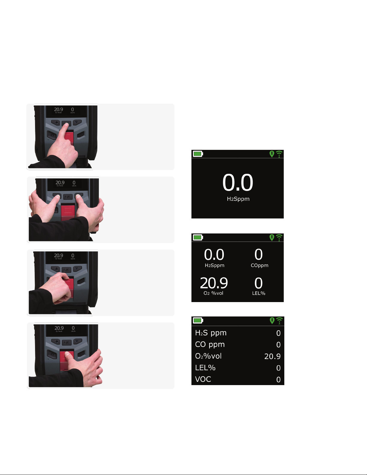
3. USER INTERFACE
3.1 BUTTONS
Interacting with EXO is easy with its high-visibility, backlit LCD display,
three-button menu system and SOS latch.
3.2 SCREEN OVERVIEW
MAIN MENU
Enter the main menu by pressing the OK button while on the gas
status screen. The main menu contains additional features and device
information available to EXO users.
GAS STATUS SCREEN
EXO’s main screen is the gas status screen. The sensor conguration of
the four-gas cartridge in EXO will determine the layout of this screen.
One gas
Four gases
Five gases
OK button
Press the OK button to
enter the main menu on
the LCD screen. Press the
OK button to conrm a
menu selection.
Up and down buttons
Use the up and down
buttons to navigate options.
Press and hold both
buttons simultaneously to
acknowledge and mute a
yellow warning alarm or a
red alert.
SOS latch pull
Pull the SOS latch to call
for help when emergency
assistance is required.
See section 4.2 for more
information.
Latch push (optional)
Push and hold the SOS latch
to record a push-to-talk
(PTT) message. Release the
latch to send the message
to devices in the same
channel. See section 6.3 for
more information.

10 || G7 EXO TECHNICAL USER MANUAL
Banner
BANNER
The banner at the top of the gas status screen is where you will nd
more information about yellow alarms, red alerts, battery life, location
and connectivity.
Battery life icon
The battery icon in the top bar of the screen shows how
much charge the battery has. See section 3.3 for more
information regarding the battery pack.
NOTE: By default, a “low battery” message will be displayed
in the banner and the battery icon will become red when
the battery’s power drops below 10%. This threshold is
congurable on Blackline Live.
2 bars: 21% to 40%
4 bars: 61% to 80%
Lightning bolt: Battery charging
Red bars: Low battery
1 bar: 1% to 20%
3 bars: 41% to 60%
5 bars: 81% to 100%
Battery life icon
Feature and status icons
Location icon
Only one location icon will be displayed at a time. See section
2.2 for more information regarding EXO’s location.
Beacon
Displayed when a beacon signal is present
Satellite positioning (GPS)
Displayed when no beacon signal is present and
satellite positioning is possible
None
Displayed when there are no beacon signals and
satellite positioning is not possible
Connectivity icon
Only one location icon will be shown at a time. See sections
1.5 and 2.5 for more information regarding connectivity.
Cellular
Displayed when EXO is connected to the Blackline
Safety Cloud through a cellular network
Satellite
Displayed when EXO is connected to the Blackline
Safety Cloud through satellite
None
Displayed when EXO is NOT connected to a cellular
network or a satellite constellation

G7 EXOTECHNICAL USER MANUAL || 11
3.3 BATTERY
All EXOs are shipped with a pre-installed battery pack and a quick charger.
Battery life
The battery pack can power EXO for over 100 days. This will vary
depending on device congurations, alarm and alert response,
operating temperature, sensor types and pump usage. In operational
temperatures below -20°C (-4°F), the battery pack’s runtime will drop
signicantly. See section 8.4 for more information about running EXO in
cold temperature.
Battery storage
For long-term storage, Blackline recommends the battery is stored at
20°C (68°F).
QUICK CHARGER
The EXO quick charger connects directly to the EXO battery and
charges it overnight. Removal of the battery from EXO must be
done in a safe environment with a clean atmosphere, specically an
atmosphere without explosive gas.
SAFETY WARNING: DO NOT allow metal tools or personal items to touch
the battery terminals. Touching metal or any conductive material to the
battery terminals is extremely dangerous and will damage the battery.
SAFETY WARNING: The EXO quick charger is NOT intrinsically safe. It
should only be used in a safe environment with a clean atmosphere.
To remove the battery
1. Power o EXO
2. Ensure EXO is in a safe environment with a clean atmosphere
3. Loosen the two self-retaining screws at the top of the battery on
the back of EXO
NOTE: This requires a 4mm hex key (included with EXO)
4. Pull the top of the battery away from EXO
NOTE: When vertical, the battery will lean away from EXO allowing
you to grip and remove the battery
Battery gauge
Press and hold the battery gauge button on the battery pack
to show how much charge the battery has.
Battery gauge while charging
The Battery gauge will automatically light up and remain lit while the
battery pack is charging. The gauge will display the current charge of
the battery pack as described above. When the battery reaches 100%
(or 5 bars on the gauge), the battery will stop charging and the gauge’s
lights will turn o.
0 bars: 0%
1 bar blinking: 1-10%
1 bar: 11-20%
2 bars: 21-40%
3 bars: 41-60%
4 bars: 61-80%
5 bars: 81-100%
Quick charge port
Self-retaining
screws, 4mm
Battery gauge
12 || G7 EXO TECHNICAL USER MANUAL
To charge the battery
1. Plug the quick charger into an outlet
2. Lift the rubber ap at the top of the battery pack to expose the
charging port
3. Plug the quick charger into the charging port
4. Charging may take up to 10 hours
NOTE: The battery pack is fully charged when the red light on the
charger turns green
5. When fully charged, remove the quick charger from the charging port
6. Replace the rubber ap to cover the charging port
To insert the battery
1. Ensure EXO is in a safe environment with a clean atmosphere
2. Hold the battery at a 45 degree angle with the bottom pointing
towards EXO
3. Place the battery bottom rst into EXO’s battery slot
4. Push the top of the battery towards EXO until it sits ush
5. Tighten the two screws at the top of the battery
NOTE: The screws should be snug, but not over-tight.
If you see an O2 stabilizing message on G7 EXO’s screen, wait up to
20 minutes for the O2 sensor to stabilize. EXO will NOT monitor during
this process. If this message persists, contact your organization’s
safety professional.
TRICKLE CHARGER
You may choose to buy an EXO Trickle Charger Kit from Blackline Safety.
This kit connects EXO directly to a power source through the power
port eliminating the need to power down and remove EXO from the
eld to charge the battery pack. See section 10.1 for more information
about the power port.
SAFETY WARNING: An attached trickle charger is ONLY intrinsically safe
when connected as described in the electrical diagrams in section 10.1.
If you see a O2 stabilizing message on G7 EXO’s screen, wait
up to 20 minutes for the O2 sensor to stabilize. EXO will NOT
monitor during this process. If the message persists, contact your
organization’s safety professional.
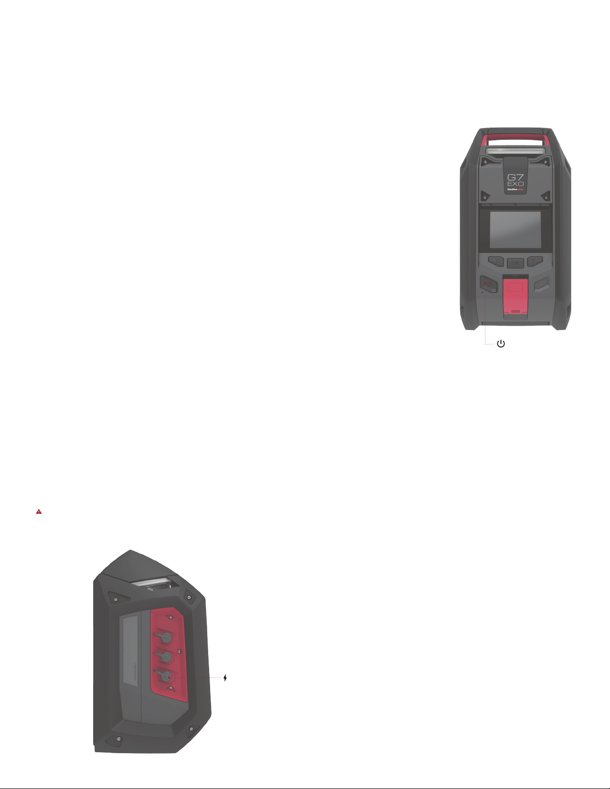
To power o EXO,
Press and hold the power button for three seconds.
NOTE: If the maintenance code is enabled, you will be required to input
the correct code to unlock EXO before powering o. See section 3.5 for
more information about the maintenance code.
You will know when EXO has nished power o when it completes the
following stages.
EXO will show a three second countdown as you hold the power
button. Every second will have a corresponding beep and ash.
At the end of the three seconds EXO will sound a chime signaling it
is powering o
The screen will go into EXO’s shutdown sequence
Once all the lights and sounds have stopped, EXO will be powered
o and disconnected from the Blackline Safety Cloud
NOTE: Make sure all red alerts have been resolved before powering o.
Do NOT power o EXO if the blue LiveResponce light is on. This may
mean waiting for monitoring personnel to contact you through EXO.
See section 4.2 for more information on red alerts.
Power button
To power on EXO,
Press and hold the power button for
two seconds. You will know when
EXO has nished its startup when it
completes the following stages.
At the end of two seconds EXO
will sound a chime, signaling it is
powering on
The top lights will ash
EXO will go through its startup
sequence and the screen will
display the active features on EXO
The green connectivity light will
stop ashing and become solid
when EXO is connected to the
Blackline Safety Cloud
3.4 POWER ON/OFF
Power port
G7 EXOTECHNICAL USER MANUAL || 13
3.6 ALARM TEST
What is the alarm test?
EXO’s alarm test is an audio/visual assessment used to ensure the siren,
speaker, LED lights and microphones are operating correctly on the area
monitor. The top lights will ash and you will hear pitches that gradually
get higher. The volume of the alarm test sounds cannot be adjusted.
When is a alarm test run?
A alarm test is run as part of the startup sequence, before all bump
tests, before each calibration and after every 24 hour period of
continuous run time.
What does a failed alarm test mean?
If EXO detects a problem while running the alarm test, the full test
will immediately be attempted two more times. If EXO still detects
a problem after the third attempt, a failed alarm test results will be
recorded and sent to Blackline Live.
NOTE: Muing the sounds during a alarm test will result in a failure. Too
loud of an environment will also result in a failed alarm test.
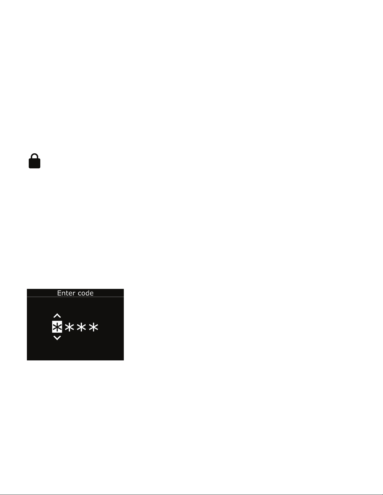
3.5 MAINTENANCE CODE
EXO features an optional maintenance code function to prevent
unauthorized individuals from changing the settings when the device
is unmanned. EXO’s entire menu, device power-down and volume
change actions are locked when a maintenance code is enabled.
Entering the code will allow you to access locked features.
Enabling the maintenance code and setting the four-number
passcode is done using the EXO configuration page available on the
Blackline Live Portal.
When the device is locked, a lock icon will be shown in the
gas status screen banner. Pressing any button while EXO is
locked will display the maintenance code entry screen.
To unlock EXO,
Press any button to display the maintenance code entry screen
You will be prompted to enter a four digit number. Use the up and
down buttons to select a number for the current digit
Press OK to move on to the next digit
After selecting the nal digit, press OK to enter the entire code
If successful, the entered code will become green and you will be
taken to the unlocked gas detection screen.
If unsuccessful, the entered code will become red. You can either
select Retry to enter another code or Back to return to the locked
gas status screen.
Enter maintenance code
14 || G7 EXO TECHNICAL USER MANUAL
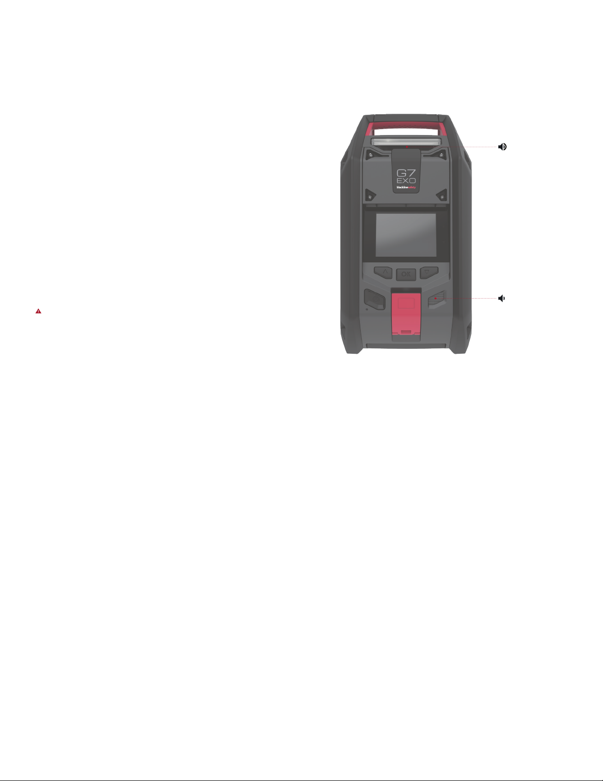
3.7 SIREN AND SPEAKER
SIREN
Gas detection yellow warning alarms and red alerts, SOS alerts and sensor
errors use the siren. To function eectively as an area gas monitor, the siren
needs to be loud enough to be heard over all environmental noise.
To adjust EXO’s alarm volume,
1. Press OK to enter the main menu
2. Select Settings
3. Select Siren volume
4. Use the up and down buttons to select the desired volume
High 105 dB – comparable to a car horn
Medium 95 dB – comparable to a lawn mower
Low 85 dB – comparable to an alarm clock
SAFETY WARNING: Listening to EXO’s siren at medium or high volumes
for extended periods of time can cause permanent hearing loss. EXO’s
siren volume should be adjusted for use indoors and in smaller spaces.
Ear protection should be worn during testing.
SPEAKER
Most yellow warning alarms, two-way calls, push-to-talk (PTT) messages
and the shutdown sounds use the speaker.
Default 85 dB – comparable to an alarm clock
NOTE: EXO’s speaker volume cannot be adjusted.
Speaker
Siren

G7 EXOTECHNICAL USER MANUAL || 15
4.1 YELLOW WARNING ALARM
EXO’s yellow warning alarm can be triggered by functional settings or
reaching low alarm gas detection thresholds. Both are congurable on
Blackline Live to best t your needs. Contact your safety supervisor to
learn more about how EXO’s features are congured.
Rapid Blinking
4. SAFETY ALERTS AND ALARMS
What do I do in the case of a yellow warning alarm?
Always follow your company’s safety protocol.
Blackline recommends that people in the vicinity of an EXO
in yellow warning alarm should leave the area. A trained
device operator may approach EXO if their safety protocol
allows it or a trained device administrator can use the
information available in
the Blackline Live Portal to
assess the situation.
Alarm information can be
read on EXO’s screen. Press
and hold the up and down
buttons at the same time
to cancel the alarm and
to let EXO know you have
read the message. In the
case of continuous gas
exposure, EXO will unmute
itself after two minutes if
detected gas levels have
not returned to normal.
4.2 RED ALERT
EXO’s red alert can be triggered by pulling the SOS latch or by reaching
high alert gas detection thresholds. Both are congurable on Blackline
Live to best t your needs. Contact your safety supervisor to learn more
about how EXO’s features are congured.
Rapid Blinking
What do I do in the case of a red alert?
Immediately follow your company’s safety protocol and
evacuate the area.
If you know the area is safe and your company’s protocol
allows you to stay in the area, read the information on EXO’s
screen. Press and hold the up and down buttons at the same
time to let EXO know you
have read the message
and to mute the alarm. In
the case of continuous gas
exposure, EXO will unmute
itself after one minute if
detected gas levels have
not returned to normal.
NOTE: Red alerts
are immediately
communicated to
monitoring personnel. Gas
levels returning to normal
or manually muting
the sound does NOT
cancel the alert sent to
monitoring personnel.
Rapid Blinking

16 || G7 EXO TECHNICAL USER MANUAL
What do I do in the case of a blue LiveResponse light?
You do not have to do anything.
This light lets you know that remote monitoring personnel are
responding to the alert by following your team’s emergency
protocol. Once monitoring personnel have conrmed the
safety of everyone in the
area and resolved the red
alert, the blue LiveResponse
light will shut o.
Depending on your team’s
response protocol, an EXO
with voice enabled can also
be contacted by monitoring
personnel to create a
two-way conversation
between the end user
and the monitoring agent
responding to the alert.
NOTE: Do NOT power o EXO
if the blue LiveResponce
light is on.
4.3 LiveResponse
EXO’s blue LiveResponse light can only be triggered by monitoring
personnel through Blackline Live. It is a signal to you that the red alert
has been acknowledged and is being investigated by monitoring
personnel. If you see this light you can be condent help is on its way.
Blinking
Other manuals for G7 EXO
4
Table of contents
Other Blackline Safety Measuring Instrument manuals


Popular Measuring Instrument manuals by other brands


Hanna Instruments
Hanna Instruments HI97710 instruction manual

C-LOGIC
C-LOGIC 85 instruction manual

ETAS
ETAS BR XETK-S3.0 user guide

PCB Piezotronics
PCB Piezotronics 422M136 Installation and operating manual

biochrom
biochrom WPA Lightwave S2000 instruction manual

Cosa
Cosa 9610 Installation, operation and maintenance manual