Volk Pictor Plus User manual

USER’S MANUAL
Volk Pictor Plus
Digital Imaging Device

IM-071 Rev G Page 2 of 50
THIS SALES PACKAGE INCLUDES:
Pictor Plus camera with optics lenses and accessories:
Model:
Description:
Accessories
Retina Module (VP2RET)
Module for eye fundus imaging
eye cup, quick user guide
Anterior Module (VP2ANT)
Module for exterior ophthalmic imaging
--------------------------------
Imaging handset (VP2HAND)
Handset for general imaging
--------------------------------
Cradle (VPCRADLE)
For data transmission and battery charging
USB cord, power unit
In addition, the sales case includes:
-(2) Batteries
-Cleaning cloth
-User manual
NOTE: Refer to the Instructions for Use page on the Volk website for the most current version
of the user manual: www.volk.com/ifu
The following accessory can be purchased separately:
-Pictor Plus Slit Lamp Adapter (VP2SLM) that enables the camera to be used as stationary
imaging tool.
QUICK START GUIDE
What to do before the first use:
1. Remove the Volk Optical Pictor Plus from the sales package and
check that all parts are undamaged.
2. Install Battery as instructed in Appendix B of this manual.
3. Place the cradle on a desk next to the PC (personal computer).
4. Connect the USB cable to the PC.
5. Connect the power cable’s plug into the wall electrical
outlet
6. Place Pictor Plus on the cradle. Battery starts to charge. Charge
battery for four hours before the first use. When device is not used, it may be stored in the
cradle.
NOTE: Camera will not automatically power up in the cradle without the power cable. User needs
to press the power button.
Guideline for placing the camera to the cradle:
The camera will fit into the cradle when it is held straight while placing it. Excessive
force must be avoided in order to prevent the camera and cradle connectors from
breaking.
Guideline for battery and device storage:
If the battery is stored out of the camera for a long period of time, ensure that the
battery is fully charged before storage. During storage, the battery must be re-
charged occasionally (e.g., every 3 - 9 months).

IM-071 Rev G Page 3 of 50
If the battery is stored in the camera, then the camera must be placed in the cradle
with the cradle power cable connected.
Device should not be used when battery cover is open.

IM-071 Rev G Page 4 of 50
TABLE OF CONTENTS
QUICK START GUIDE ....................................................................................................................... 2
TABLE OF CONTENTS....................................................................................................................... 4
1INDICATIONS FOR USE............................................................................................................. 5
2ESSENTIAL PERFORMANCE...................................................................................................... 6
3CONTRAINDICATIONS FOR USE OF THE EYE OPTICS RETINA MODULE VP2RET AND THE EYE
OPTICS ANTERIOR MODULE VP2ANT...................................................................................... 7
4WARNINGS AND CAUTIONS .................................................................................................... 8
5IMPORTANT SYMBOLS ............................................................................................................ 9
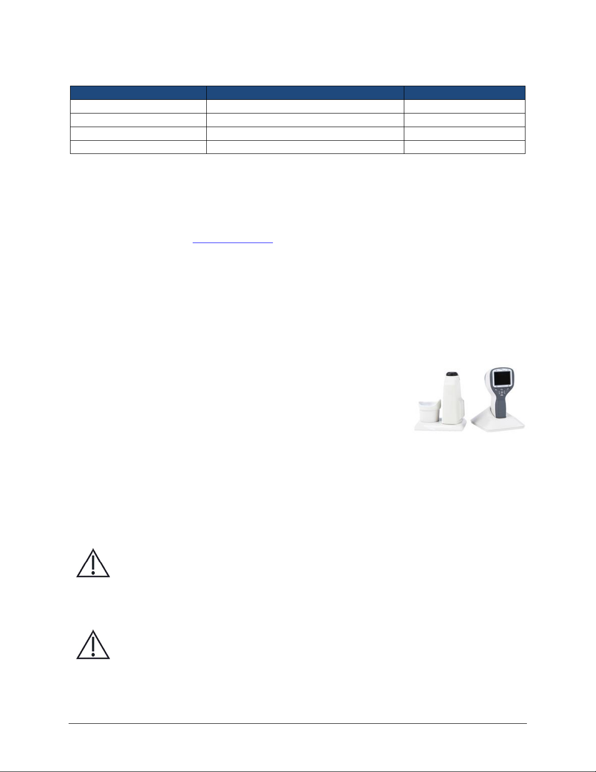
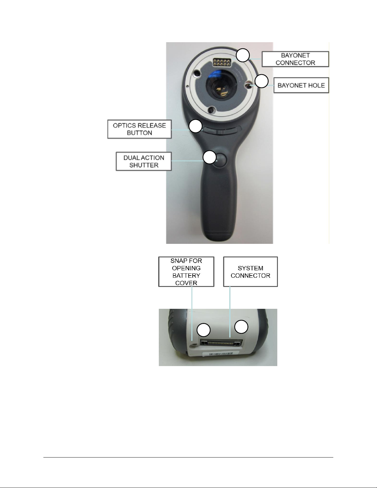
6PARTS OF THE DEVICE ........................................................................................................... 10
7USAGE ENVIRONMENT REQUIREMENTS............................................................................... 14
8OPERATING INSTRUCTIONS................................................................................................... 15
8.1. Preparations ................................................................................................................... 15
8.2. Connection to a PC......................................................................................................... 15
8.3. Basic use –starting up, shutting down, and taking an image........................................ 16
8.4. Attaching and detaching optics module ........................................................................ 17
8.5. Device Menu .................................................................................................................. 17
8.6. Patient List editor ........................................................................................................... 21
8.7. Adjusting focus and automatic focus ............................................................................. 21
8.8. Patient Information........................................................................................................ 22
8.9. Reset button................................................................................................................... 26
9RETINAL IMAGING USING OPTICS MODULE VP2RET ............................................................ 26
9.1. Steps for Retinal Imaging: .............................................................................................. 26
10 EYE IMAGING USING ANTERIOR OPHTHALMIC MODULE VP2ANT....................................... 31
10.1. Steps for Eye Surface Imaging:....................................................................................... 31
11 ERROR MESSAGES ................................................................................................................. 37
12 CLEANING INSTRUCTIONS ..................................................................................................... 38
13 DEVICE MAINTENANCE.......................................................................................................... 39
14 TECHNICAL DESCRIPTION ...................................................................................................... 40
15 WARRANTY ............................................................................................................................ 43
APPENDIX A ELECTROMAGNETIC COMPATIBILITY INFORMATION ......................................... 44
APPENDIX B REPLACING THE BATTERY.................................................................................... 48

IM-071 Rev G Page 5 of 50
1INDICATIONS FOR USE
Pictor Plus is a medical digital camera that is used with dedicated optic lenses intended to take images
of the eye fundus, and surface of the eye.
Supported optic lenses and their intended uses are:
Component:
Description:
VP2RET
Module for fundus imaging. The Pictor Plus VP2HAND digital camera
with the VP2RET optics module is intended to capture digital images
and video of the fundus of the human eye.
VP2ANT
Module for exterior ophthalmic imaging. The Pictor Plus VP2HAND
digital camera with the VP2ANT optics module is intended to capture
images and video of the surface of the human eye and surrounding
areas.
The device may only be operated by persons who have been properly trained or who have the required
knowledge and experience to do so.

IM-071 Rev G Page 6 of 50
2ESSENTIAL PERFORMANCE
The essential performance of Volk Pictor Plus camera is to take images and video for consultation and
documentation purposes with safe illumination levels according to the standard ISO 15004-2:2007.

IM-071 Rev G Page 7 of 50
3CONTRAINDICATIONS FOR USE OF THE EYE OPTICS RETINA MODULE VP2RET AND THE EYE
OPTICS ANTERIOR MODULE VP2ANT
Because prolonged intense light exposure can damage the retina, the use of the device for ocular
examination should not be unnecessarily prolonged, and the brightness setting should not exceed what
is needed to provide clear visualization of the target structures.
The retinal exposure dose for a photochemical hazard is a product of the radiance and the exposure
time. If the value of radiance were reduced in half, twice the time would be needed to reach the
maximum exposure limit.
While no acute optical radiation hazards have been identified for direct or indirect ophthalmoscopes, it
is recommended that the intensity of light directed into the patient's eye be limited to the minimum
level which is necessary for diagnosis. Infants, adults, and persons with diseased eyes will be at greater
risk. The risk may also be increased if the person being examined has had any exposure with the same
instrument or any other ophthalmic instrument using a visible light source during the previous 24 hours.
This will apply particularly if the eye has been exposed to retinal photography.
Pictor Plus VP2RET and VP2ANT are classified as Group 2 based on standard ISO 15004-2:2007. The
daily usage time and maximum allowed number of pulses is calculated based on optical classification
results according to standard ISO 15004-2:2007.
CAUTION:
The light emitted from this instrument is potentially hazardous. The longer the
duration of exposure and the greater the number of pulses, the greater the risk of
ocular damage. Exposure to light from this instrument when operated at maximum
output will exceed the safety guideline after:
Maximum number of pulses (still images) allowed daily:
-VP2RET: 6300 pulses (still images) / eye
-VP2ANT: 250 pulses (still images) / eye
Total daily usage time for continuous light (video usage time and aiming light duration)
shall be limited to:
-VP2RET: 1 hour 30 minute video usage / eye
-VP2ANT: 8 minute video usage / eye

IM-071 Rev G Page 8 of 50
4WARNINGS AND CAUTIONS
Use only the accessories and battery provided by Volk Optical with this product.
Place PC and cradle outside of the patient environment (at least 4 feet distance from
the patient).
Connection between the camera and the workstation is USB and/or Wi-Fi. Any
authorization procedures should be carried out in the workstation.
Images and videos can be copied from camera to workstation via USB and/or Wi-Fi,
and then viewed in the workstation.
USB write protection is on by default. When protection is on this feature will prevent
writing to camera memory card from PC when connected to the cradle.
USB connection works without power cable. There is no USB charging in Pictor Plus
camera.
No modification of this equipment is allowed.

IM-071 Rev G Page 9 of 50
5IMPORTANT SYMBOLS
Symbol
Description
The CE mark on this product indicates it has been tested and
conforms to the provisions noted within the 93/42/EEC Medical
Device Directive.
2797
CE mark with notified body identification number indicates a
Class IIa product.
Read accompanying user documentation indicates that important
operating instructions are included in this User’s and Maintenance
Manual. Failure to follow these instructions could place the patient or
operator at risk.
WARNING
Indicates a hazardous situation which could result in patient injury,
harm or death if the appropriate safety precautions are not followed.
CAUTION: Indicates the need for the user to consult the instructions
for use for important cautionary information such as warnings and
precautions that cannot, for a variety of reasons, be presented on the
device itself.
Type BF applied parts. Applied part is a part of Pictor Plus that in
normal use necessarily comes into physical contact with the patient.
9V / 1.1A
Charger polarity symbol, voltage, and power.
The symbol indicating separate collection for Waste Electric and
Electrical Equipment per Directive 2002/96/EC.
The symbol indicating that the device is capable of wireless data
communication based on the 802.11 IEEE network standard. When
using Wi-Fi functionality, interference may occur in the vicinity of
equipment.
Sticker at the front of the device indicating Volk Optical’s address,
integrated general imaging optics focal length, and F-number.

IM-071 Rev G Page 10 of 50
6PARTS OF THE DEVICE
1. Bayonet
connector
2. Bayonet hole
3. Optics release
button
4. Dual action
shutter
5. Snap for
opening
battery cover
6. System
connector
1
2
4
3
5
6

IM-071 Rev G Page 11 of 50
7. Connection
LED
8. Reset button
9. Power LED
10. Right soft key
11. Left soft key
12. Middle key
13. Arrow keys
CRADLE:
14. Cradle docking
connector
15. USB cord
16. Power cord
14
7
8
10
12
9
11
13

IM-071 Rev G Page 12 of 50
SOFT KEY INDICATORS:
Position
Indicator
Purpose
Left soft key
To power on the device
To power off the device, with long press
Right soft key
Open menu with long press
LED INDICATORS:
The recharging and connection to PC is indicated with green (charging) and blue (connection) LED-lights:
Position
Indicator
Purpose
Left LED-indicator Green
Active when device is powered on, blinking when charging
in cradle
Right LED-indicator Blue
Active when device is sitting in the cradle and connected to
a PC

IM-071 Rev G Page 13 of 50
GRAPHICAL INDICATORS:
These indicators are displayed on the top row of the display during imaging:
1. S=Still, V=Video
2. Folder number
3. Optics: RET (eye), ANT (eye surface), FA (angiogram), DF (no lens)
4. Battery level
5. Time
6. Variable indicator (changes with optics module according to middle key function)
7. Variable indicator with ANT optics attached: W=white light, B=blue light
8. Zoom indicator
9. Diopter compensation indicator in manual focus mode with RET optics attached
10. Brightness indicator
11. Variable indicator (changes with optics module according to left soft key function)
12. Variable indicator with RET optics attached: Target hi, Target low, Target off
13. Focus mode: Manual/Auto/AF Assist with RET optics attached
5
2
3
7
4
1
6
8
10
9
11
12
13

IM-071 Rev G Page 14 of 50
7USAGE ENVIRONMENT REQUIREMENTS
CAUTION:
Pictor Plus is not suitable for use in the presence of flammable anesthetics.
Pictor Plus is intended to be used inside; within a normal room temperature and a
normal humidity environment. Do not use Pictor Plus in an environment where there
is a possibility for water to condense on or inside the Pictor Plus. The type of power
supply required is indicated in the Technical Description section.
CAUTION:
It is only allowable to attach the USB cable and power source provided in the sales
package into the cradle. If you need replacements to the USB cable or power source,
then please contact the Manufacturer or your own Retailer.
The USB cable must be connected only to the USB port of a PC computer that
complies with the IEC 60950 standard. Avoid using excessive power or twisting the
connector when connecting the USB cord to a PC.
Place PC and cradle outside of the patient environment (at least 4 feet distance from
the patient).
To transfer patient image data, the device must be used together with a computer running either
Microsoft Windows 7®, Windows 8® and Windows 10®. The device does not need any drivers to be
installed on the computer.
Writing to the SD card from a PC is not enabled by default.
The device can be used with all major patient database applications supporting both textual and image
data recording.
The device must be used according to this manual, quick reference guide, and/or information found on
Volk Optical’s website www.volk.com.
Electromagnetic compatibility information and recommended separation distances between portable
and mobile RF communications equipment and the Volk Optical Pictor Plus are given in Appendix A.

IM-071 Rev G Page 15 of 50
8OPERATING INSTRUCTIONS
This chapter gives instructions for using the device. More specific instructions for using optics lenses are
given in the optics lens specific chapters.
8.1. Preparations
Pictor Plus is both charged and connected to a PC using the provided cradle. When Pictor Plus is not
used, it may be stored in the cradle. Storing the device in the cradle is not harmful for the battery
because the battery is charged only when the charge has dropped below a certain limit.
To connect Pictor Plus to the cradle, gently place it into the connector hole. The device can be
connected to the cradle with optics attached.
8.2. Connection to a PC
Image data transfer method to a PC is similar as with a digital
camera.
When connected to a PC running Microsoft Windows 7®, Windows
8® or Windows 10® operating system, displays a drive letter for Volk
Pictor. Simply open the folder to view and then store files to the
hard disk of the PC.
Writing to the SD card from a PC is not enabled by default.
WIFI functionality enables wireless image transfer from camera to PC. Image transmission system is shown
below:

IM-071 Rev G Page 16 of 50
8.3. Basic use –starting up, shutting down, and taking an image
The device is powered on by pressing the left soft key.
Pictor Plus verifies if image data is to be erased when:
Device is powered on from power off mode or power save mode
Device is removed from the cradle
It is recommended that image data storage is always erased when using device with a new patient.
The device offers the possibility to edit the current patient information.
It is possible to capture both still images and video. Image capture mode is changed from the device
menu that opens by pressing the right soft key for 1 second.
Still image is captured by fully depressing the dual action shutter to the second position. When set to
Video mode, video is captured by keeping the dual action shutter pressed down in the second position.
A taken image will stay on the display until it is cleared by pressing the right or left soft key. The image
can be zoomed during instant preview by pressing the middle key. There are four zoom levels. Pressing
the middle key activates the next level. Move around the image by using arrow keys.
To transfer images to a PC, place the device into the cradle. The image transfer and charging is indicated
with green and blue LED lights and text on the LCD screen. In case the WIFI connection is active, images
are transferred to the PC automatically.
NOTE:
If images are corrupted or not transferred to the PC, the original images are saved to the memory card.
Please try again to transfer images to the PC via USB.
The device is powered off by keeping the left soft key pressed down for over 1 second.
NOTE:
When device is powered on, powered off or goes to standby mode the camera focus motor may make a
sound. This sound is normal and is not a sign of any damage or problem.

IM-071 Rev G Page 17 of 50
8.4. Attaching and detaching optics module
CAUTION:
Optic modules used with Volk Optical Pictor Plus must include text “PICTOR PLUS”or
“PICTOR”. Please do not attach other objects to the bayonet connector.
Optics are attached
by placing it in front
of the bayonet area
of the device. Three
bayonet legs are
placed on the holes
and optics is
pressed firmly to
lock into the device.
1. Bayonet legs
2. Bayonet holes
Optics are released
by sliding release
button that is
located in front of
the device above
the dual action
shutter.
3. Optics release
switch
8.5. Device Menu
The menu is opened by pressing the right soft key for
1 second.
The menu has six tabs. One is for device settings, such as
language selection. There is one tab for retinal imaging
(RET), fundus angiogram imaging (FA), anterior eye
imaging (ANT), and general imaging (DF).
The arrow keys are used to move between tabs: use the
arrow up key until tab is active and use left and right
arrow keys to change active tab. A light blue color
indicates an active tab.
The arrow keys change values in the menu. An active
value is indicated with a light blue color. Changed values
are saved by using the left soft key (“Ok”) and cancelled
by pressing the right soft key (“Cancel”). Some values are
confirmed by pressing the middle key.
3
1
2

IM-071 Rev G Page 18 of 50
The table below includes explanations of the device settings tab:
Setting
Values (default
bolded)
Purpose
Preview images
Ok
To preview the images on the camera, press the
middle button.
New patient folder
Ok
To create a new patient folder, press the middle
button. A new patient folder can also be created in
live view by long pressing the middle key.
Erase image memory
Ok
Select the middle button to erase images and videos
from the camera SD card.
Edit patient list
Ok
Press the middle key to edit patient list.
Patient information
On/Off
Enable or disable patient information linking.
Display brightness
Low-Med-High
Use left and right arrow keys to adjust display
brightness.
Icons
On/Off
Show graphical icons when imaging.
Sounds
On/Off
When enabled, sound is played during image capture.
Keyboard backlight
On/Off
When enabled, keyboard illumination is on.
Select language
ENG-FIN-FRA-GER-
ITA-JPN-POR-SPA-
ZHO
Use left and right arrow keys to select camera
language.
USB write protection
On/Off
When enabled, writing to SD card is not allowed while
the device is in the cradle. This feature helps prevent
any viruses getting from the PC to the camera.
Video file format
MPEG4/MPEG1
Use left and right arrow keys to select video file
format.
Image transfer
method
UMS/WIA
Use WIA for automatic and UMS for end-user
activated image transfer. UMS can be used in most
cases.
Restore factory
Setting
Ok
To restore all settings menus to factory defaults.
Activate using the middle key.
SD card firmware
update mode
Ok
To start SD card firmware update mode, press middle
button.
Date
DD-MM-YYYY
Use up and down arrow keys to set date.
Time
HH:MM
Use up and down arrow keys to set time.
Camera SW version
Show camera SW
version
Browse version information with left and right arrow
keys.
Start query
Era./Fol./None
Choose the startup query between memory erase,
new patient folder, or no query at all.
Wireless
On/Off
Enable or disable wireless connection
Wireless info
Ok
To view ‘WLAN SSID’ and ‘WLAN Password’, press
middle button.

IM-071 Rev G Page 19 of 50
Preview images
Image preview is opened by selecting “Preview files” with the middle key. Images are browsed by using
arrow keys. The display gives information about usage of the image preview.
The image can be zoomed while previewing by pressing the middle key. Move around the image by
pressing arrow keys. Change between the four zoom levels by pressing middle key.
Patient ID information can be edited in image browser.
New Patient Folder
A new patient folder is created by pressing the middle key when the “New patient folder”selection is
active on the device menu. A new patient folder can also be created by pressing the middle key for
3 seconds when in the live view. If the current patient folder is empty, then a new folder cannot be
created. Patient ID information can be edited after creating a new patient folder.
Erase Image Memory
Image memory can be erased by selecting “Erase image memory” in the device menu. This selection is
activated by pressing the middle key. The camera also prompts the question “Erase image memory?”
when the camera is powered on or removed from the cradle.
Edit patient list
User can add or remove patients from patient list.
Patient information
Enable or disable patient information linking.
Display brightness
The display brightness selection has three options: low, medium, and high. Choose the suitable level of
display brightness according to, for example, how the examination room is lit up.
Icons
The icons shown on the camera screen can be enabled or disabled to the user’s liking. The most
essential icons, such as the menu icon, are always visible.
Sounds
By default, the camera makes a sound during image capture. This sound can be turned off from the
device menu.
Keyboard backlight
By default, the camera keys have a backlight lit up while the camera is turned on. This light can be
turned off from the device menu if it disturbs the user while taking images.
Language
The camera has nine different languages that the user can choose from. The default language is English
and the language selection is always shown in English on the menu.
USB write protection
USB write protection is recommended to be turned on by user. When protection is on, this feature will
prevent any virus from entering the camera from a PC when connected to the cradle.

IM-071 Rev G Page 20 of 50
Video file format
The camera has two file formats that the user can choose for videos: MPEG4 and MPEG1. MPEG4 is a
higher quality file format but may not be compatible with all video players. MPEG1 format is more
widely supported by different software applications.
Image transfer method
There are three options for the image transfer method: UMS (USB Mass Storage) or WIA (Windows
Image Acquisition) and WiFi.
Restore factory settings
By selecting “Activate” in the device menu, “Restore factory defaults” selection, the original factory
settings will be returned.
SD card firmware update mode
If the device has WiFi functionality, SD card firmware can be updated by pressing middle button. The
device must be placed on cradle for SD card firmware update. If PC prompts a message to insert the SD
card, press any camera key to continue update.
Date
The date can be set using the left and right arrow keys. Move between day, month, and year by
pressing the middle key. The date format is DD MM YYYY for English, Finnish, German, French, Italian,
Spanish, and Portuguese. The date format is MM DD YYYY for Japanese.
Time
Time can be set using the left and right arrow keys. Move between hours and minutes by pressing the
middle key.
Camera SW version
This item in the device menu tells the camera software version.
Start query
The user can choose start-up query between erasing images, creating new patient folder, or no query at
all. When erasing images is chosen as the query, the camera will prompt the user on start-up whether
all images and videos shall be deleted. When new patient folder query is chosen, the camera will ask if a
new patient folder shall be created upon start-up to prevent from mixing images with previous patient.
If no query is selected, then the camera will go directly to live view upon start-up.
Wireless
By default, wireless connection is on. User can enable or disable wireless connection. When wireless
connection is enabled, the wireless symbol is shown on display next to the battery level indicator.
Wireless info
Press middle key to view wireless connection information. ‘WLAN SSID’ and ‘WLAN Password’ are shown.
This manual suits for next models
2
Table of contents