Voltacon Li-2021 48100R User manual

Lithium Ion Li2021 ESS48-2U-L LFP Battery User Manual
Silent Power Lithium Ion Battery
Li-2021 48100R
User Manual
V1.2

Voltacon Li5120 – ESS LFP Battery User Manual
1
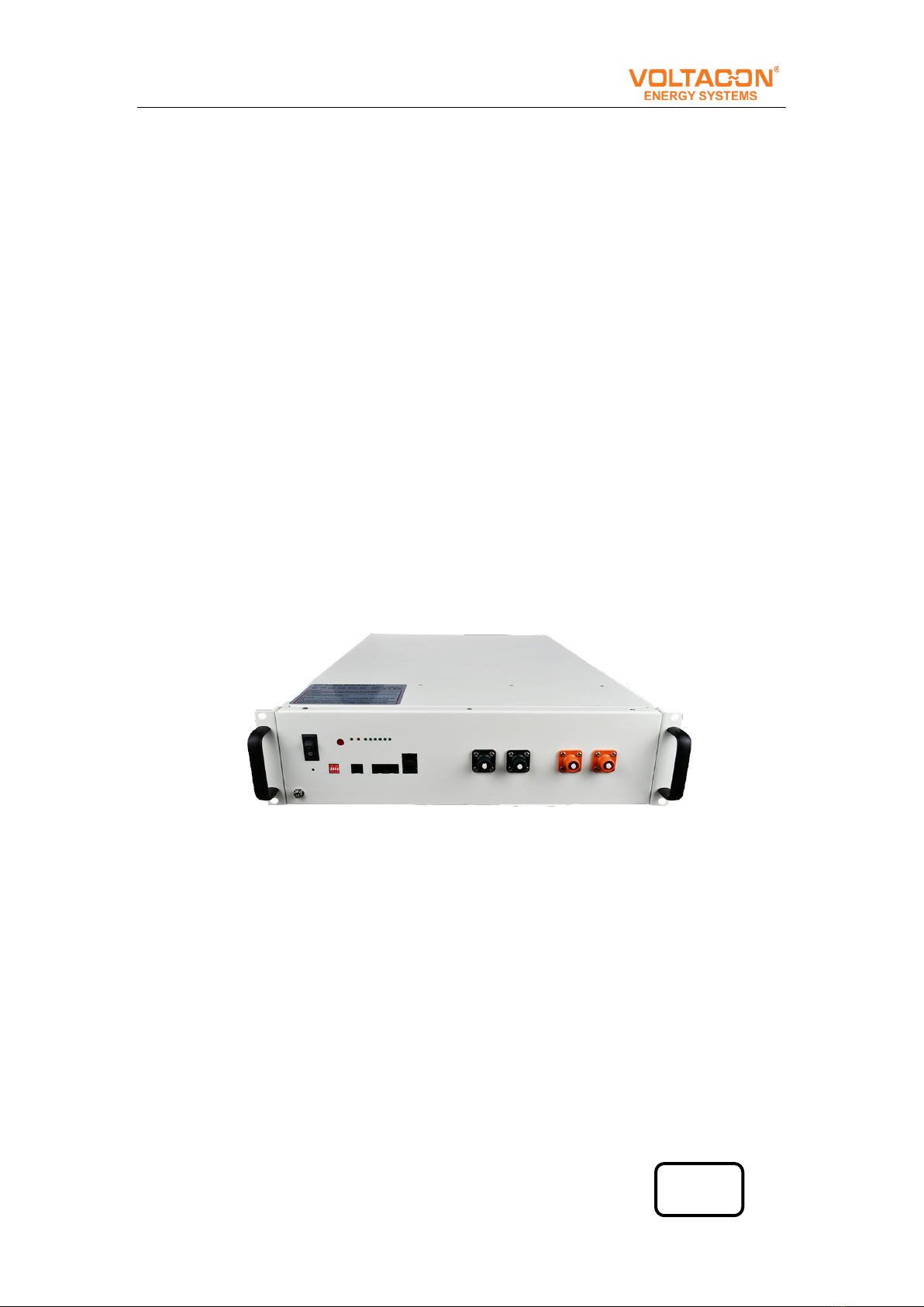
Li5120 / 48100R LFP Lithium Iron Phosphate Battery
Dear customer,
This is your Voltacon Li-2021 / 48100R LFP battery for home energy
storage system. We provide safe, well-designed and high-performance
standard LFP battery pack for you. The battery pack is compact, easy to install,
free of maintenance and used as the building block of energy storage system
by assembling in parallel. It is widely applied in home applications, small
commercial and industrial energy storage system as well as Telecom stations.
This manual contains all the information necessary to install, use and
maintain the LFP battery. We kindly ask you to read this manual carefully before
using the product.
This manual is meant for the installer and the user of the LFP battery. Only
trained and qualified staff may install and perform maintenance on the LFP
battery.
The boundaries of its use, as described in this manual should be kept in
mind. The LFP battery may not be used in medical or in aviation related
applications. The LFP battery may not be used for any purposes other than
described in this manual. Using the LFP battery for any other purpose will be
considered improper use and will void the warranty of the product. VOLTACON
cannot be held responsible for any damage caused by improper, incorrect or
unwise use of the product. Read and understand this manual completely before
using the product. During the use of the product, user safety should always be
ensured, so installers, users, service personnel and third parties can safely use
the LFP battery.
This is the original manual, keep it in a safe location! Please consult
www.voltacosolar.com for the latest version of all manuals.
VOLTACON UK LIMITED
Burnsall Road | Industrial Estate | Canley | Coventry | CV5 6BU| United Kingdom
Website https://ww.voltacon.com
Tel: +44 2477 675 575
Email: [email protected]

Voltacon Li5120 – ESS LFP Battery User Manual
2
1 Specifications
Table 1-1 Battery Pack Specifications
Battery Model Li-5120 / 48100R
Chemistry LFP
Nominal Voltage 51.2V
Voltage Range 44.8V-57.6V
Nominal Capacity 100Ah
Nominal Energy 5.12kWh
Unit Dimension L480mm* W620mm * H117mm(2.6U)
Unit Weight 51kg
Standard Charge Current 50A
Maximum Charge Current 50A
Standard Discharge 50A
Maximum Discharge Rate 70A
Round-Trip Efficiency ≥95%
Communication Protocol RS232, RS485, CAN
@90%DOD, ret@80%, 25℃
Calendar Life ≥10years
Operating Temperature Charge: 0℃~ 45℃, Discharge: -20℃~ 55℃
Certificates IEC62619 / UN38.3
Storage Temperature Within 1month: -20~45°C

Voltacon Li5120 – ESS LFP Battery User Manual
3
1-3months: -20~35°C
3-12months: 20~25°C
1.1 Product standard configuration
Items Quanti
ty Specifications Pictures
Li-5120/48100R 1pcs
51.2V/100Ah LFP pack;
including BMS, three
interfaces (CAN/RS-
485/RS232), 2 Link ports,
LED power indicator and
insulated coating metal
case.
Power Cable
1set
Connect battery to battery;
0.2m; Positive and negative
Communicate
Cable 1pcs
Connect battery to battery;
0.2m;CAN or RS485
communicate
Earthing cable
1pcs 1m
User Manual
1pcs
Please read the User
manual before you use this
product.

Voltacon Li5120 – ESS LFP Battery User Manual
4
2 Interface and protection functions
2.1 Battery front panel
2.2 Battery front panel schematic
2.3 Components
No.
Name
Label
Functions description
1 Power button POWER
Power button. When switched to "ON",
the system can be activated by the
"SW" key or external power supply;
when switched to "OFF", the system is
off.

Voltacon Li5120 – ESS LFP Battery User Manual
5
Power Indicator When the switch is turned "ON", the
power indicator is on.
2 DIP switch ADD Select the match manufacturer, see the
match list(appendix A)
3 Soft start switch SW
Press and hold this button for 1
second while the switch key is "ON"
to enter Start or Sleep mode
4
Running lights RUN
Green lights. The lights flash when
Standby. The lights are constantly on
when charging. The lights flash when
discharging.
Alarm indicator ALM
Red light. The lights flash when
Alarm. The lights are constantly on
when Protected.
5 RS-232C
communication port RS232 Communication with the upper
computer
6 Power indicator CHARGE
A total of 6 green lights showing
battery capacity, each representing
16.7% of SOC.
7 External CAN
communication port CAN Communication with external devices
8 External RS-485
communication port RS485 Communication with external devices
9Cascade terminal Link Port
Used for master-slave cascade
communication. Connected with a
standard direct-connected network
cable, the master is connected to
PORT1, and the slave is connected
to PORT0.
10 Positive Pole and
Negative Pole + -

Voltacon Li5120 – ESS LFP Battery User Manual
6
2.4 Battery Management System (BMS)
Voltacon BMS is an electronic system that manages lithium ion
batteries such as by protecting the battery from operating outside its safe
operating area, monitoring its state, calculating secondary data,
reporting that data, controlling its environment, authenticating it and
balancing it. The high performance of BMS is guaranteed by adopting
Automotive-level chips and self-developed sophisticated DLGOS BMS
software.
3 Operating Environment
Battery operating environment requirements:
Operating Temperature: -20℃~55℃
Relative Humidity: 20%-80%, no condensation
Altitude: <4000m
Site environment requirements: Keep away from heat source, avoid
direct sunlight, no corrosive gas, no explosive gas, no insulating gas, no
insulating conductive dust.

Voltacon Li5120 – ESS LFP Battery User Manual
7
4 Packaging, transportation, storage
requirements
4.1 Transportation
Always check all applicable local, national, and international
regulations before transporting an LFP battery.
During the transportation, protected the battery from severe
vibration, shock or squeezing during transportation, as well as to prevent
sun and rain.
During the loading and unloading process, the battery should be
handled lightly and protected against falling, rolling and heavy pressure.
4.2 Storage
Follow the storage instructions in this manual to optimize the
lifespan of the LFP battery during storage. If these instructions are not
followed and the LFP battery has no charge remaining when it is checked,
consider it to be damaged. Do not attempt to recharge or use it. Replace
it with a new LFP battery.
See previous storage temperature conditions.
The self-discharge of the LFP battery is 1-2% per month. Keep the
battery SOC to 40%-60% during storage.
1. Disconnect the LFP battery from all loads and, if present, the
charging device.
2. Store the battery in a cool and dry place without direct sunshine.
2. Keep the battery away from corrosive substances, inflammable
and explosive material as well as hazardous gases.
4. For long-term storage (>6months), charge the LFP battery to more
than 80% of its rated capacity before storage. The battery needs to be
recharged every 6months to more than 80%of the rated capacity.

Voltacon Li5120 – ESS LFP Battery User Manual
8
5 Installation and configuration
5.1 Installation preparation
5.1.1 Safety Requirements
Only those who have been trained in the power system and have a
good knowledge of the power system are allowed to install the device.
Always observe local safety regulations and the safety requirements
listed below during installation process.
Before installing or removing the device, make sure that the power
system is not powered and that the battery device is turned off.
Distribution cabling should be reasonable and with protective measures
to avoid being touched during operation.
5.1.2 Checking the operating environment
The operating environment should meet the requirements
described in Chapter 4, “Operating Environment”. Otherwise, it needs to
be adjusted and re-examined.
5.1.3 Tools
The tools that may be used are shown in Table 6-1.
Table 6-1 Tools
Tools
Screwdriver (Slotted, Phillips) Multimeter
Wrench clip-on ammeter
Diagonal pliers Insulating tape
Thermometer Pliers
Anti-static wrist ring Clip Pliers
Tapes Strippers

Voltacon Li5120 – ESS LFP Battery User Manual
9
5.1.4 Technical preparation
Electrical interface settings:
If the battery is connected to the user device directly, please check:
●Whether the DC charging interface of the energy storage inverter
meets the charging voltage and current requirements in Table 2-1
Battery Pack Specifications.
●Whether the power of the electrical equipment matches the
parameters listed in “Table 2-1 Battery Pack Specifications”;
Security check:
Fire-fighting equipment such as portable dry powder fire
extinguishers should be available near the equipment. Do not place
dangerous materials such as flammable or explosive ones near the
battery.
5.2 Unpacking
●When the battery arrives at the installation site, it must be loaded and
unloaded properly and prevented from the direct sunshine and rain.
Before installation, check if there is any component missing according
to packing list attached in the packing box and check whether the box
appearance is intact;
●Carefully handling during the unpacking. Protect the insulated coating
on the case surface;
●Check the LFP battery for damage after unpacking. If there is any
damage, contact Voltacon or your reseller.

Voltacon Li5120 – ESS LFP Battery User Manual
10
5.3 The preparatory work
1. Make sure the POWER buttons of all batteries are OFF
2. Ensure the charging voltage of power supply equipment is DC57.5±
0.1V;
3. All power supply should be off
5.4 Installation
5.4.1 Install the battery
The E-BOX-48100R can be installed either vertically or horizontally.
In this chapter, it’s mainly instructions for horizontal installation such as:
installation in a 19-inch cabinet. Vertical installation is similar. All
equipment must be steady during installation.
5.4.2 Connect Ground cable
Unscrew the screw at the grounding hole on the front panel of the
battery, wrap the ground cable around the screw, and tighten with a
screwdriver. Connect the other end of the ground cable to a reliable
ground point.
Note: The grounding resistance should be less than 1Ω.
5.4.3 Connecting the power cable
Before connecting the power cable, connect and disconnect the
cable to identify the positive and negative terminal, then make a mark
respectively. After the cable is connected, measure whether there is a
short line or reverse connection.
Connecting the power cables:

Voltacon Li5120 – ESS LFP Battery User Manual
11
(1) Power cable connection instructions of Single-Rack:
●Single battery: Connect the positive pole of the battery to the positive
terminal of the DC port of the energy storage inverter (or the junction
box) with a red cable, and connect the negative pole of the battery to
the negative terminal of the DC port of the energy storage inverter (or
the junction box) with a black cable.
●Multiple batteries: the connection between batteries, as well as the
connection between the battery and ESS inverter is in parallel. First,
connect the two positive terminals of adjacent batteries with the red
cable; connect the two negative terminals of adjacent batteries with
the black cable; connect the positive pole of the battery with the
positive terminal of the DC port of the energy storage inverter (or the
junction box) with a red cable; connect the negative pole of the battery
with the negative terminal of the DC port of the energy storage
inverter (or the junction box) with a black cable.
(2) Power cable connection instructions of Multi-Rack:
Collect the positive and negative power cables respectively by the
bus bar or junction box, then connect two racks in parallel.
The length, thickness, material, and resistance of the cables
connected in parallel should be the same.
Note: When the cable is inserted into the positive and negative
terminals of the battery and “Click”, the cable is firmly connected. Before
pulling out the cable, press the small button next to the terminal. When
multiple batteries are connected in parallel, in order to reduce the
influence of the circular current, the overall positive and negative output
cables can be connected from different batteries.
Figure 6-1 Schematic diagram of battery connection

Voltacon Li5120 – ESS LFP Battery User Manual
12
5.4.4 Connecting communication cables
Single battery: Choose which port to be inserted according to the
communication protocol (RS485/CAN/RS232) between the battery
and ESS inverter, then insert the communication cables to the port;
Multiple batteries: The host and the slave communicate in
cascade mode: one is the host and the rest are the slaves. Please
refer to the following picture for the cascade connection. then, insert
the communication cable to the port according to the communication
protocol between batteries and ESS inverter.
1. The host Link Port 0 must be kept free;
2. The end slave Link Port 1 must be kept free;

Voltacon Li5120 – ESS LFP Battery User Manual
13
5.4.5Activation
1. Before activation, check again if all cables are properly and
firmly connected, also make sure there is no short circuit and reverse
connection;
2. Turn all battery POWER buttons to “ON”;
3. Single battery: press the SW button of the battery for 1 second.
If the 8 indicator lights of the battery are on for 1 second, the battery
is activated.
Multiple batteries: press SW button of any battery for 1 second.
If 8 indicator lights of all batteries are on for 1 second, all batteries
are activated.
Note: When the battery power is too low to be turned on, charge
the battery by connecting the battery to ESS inverter.
5.4.6 Power-on test
1. Turn on the battery and energy storage inverter or DC power
supply;
2. Check whether the battery is operating normally by referring
to "table 6-3 LED instructions";
1) If the battery is not fully charged and the energy storage
inverter has successfully charged the battery, then the battery enters
the charging state;
2) If the battery is fully charged and the battery does not supply
power to the load, the battery enters the standby state;
3) If the battery is supplying power to the load, the battery enters
a discharging state.
Table 5-1 LED indications

Voltacon Li5120 – ESS LFP Battery User Manual
14
Battery
status
Protection
/ Alarm /
Normal
RUN ALM Capacity LED
Descriptions
●●●●●●●●
Shut down OFF OFF OFF OFF OFF OFF OFF OFF All off
Power-on Normal ON ON ON ON ON ON ON ON
The indicator light is on for
about 1 second at power-on.
Standby
Normal Flash 1 OFF OFF OFF OFF OFF OFF OFF
Indication when the battery
is not charging or
discharging
Alarm OFF
Flash 3
OFF OFF OFF OFF OFF OFF Battery low voltage
Charging
Normal Light OFF According to the power indicator, each
LED lamp represents 16.6%SOC,
constantly bright means full, off means
uncharged, and flicker means charging
Alarm Light
Flash 3
Protection OFF Light OFF OFF OFF OFF OFF OFF Stop charging, protect start
Discharge
Normal Flash 3
Flash 3
According to the power indicator,
each LED lamp represents 16.6%SOC,
constantly bright means full, off means
uncharged, and flicker means charging
Alarm Flash 3
Flash 3
Protection OFF Light OFF OFF OFF OFF OFF OFF Stop discharge, protect start
Note: The flashing instructions, flash 1-0.25s light/3.75s off; flash 2-0.5s
light/0.5s off; flash 3-0.5s light/1.5s off.
---End of installation---

Voltacon Li5120 – ESS LFP Battery User Manual
15
6 Communication
There are RS-232C, RS485and CAN communication ports on the
battery. The battery status can be obtained or the battery internal
parameters can be modified via host computer.
6.1 RS232 port
Table 6-1 RS232 Connector Pin Assignments
RS-232C port
Pin number Signal
1 GND
2 TXD
3 RXD
4 GND
Default baud rate of RS-232C ports: 9600bps.

Voltacon Li5120 – ESS LFP Battery User Manual
16
6.2 RS485 port and CAN port.
Table 6-2 RS485 and CAN Connector Pin Assignments
Pin number Serial CAN
1 RS485B --
2 GND
3 RS485A CANH
4 -- CANL
5 --
6 GND --
7 --
8 --
Default baud rate of RS-485 port: 115200bps
Default baud rate of CAN port: 5K

Voltacon Li5120 – ESS LFP Battery User Manual
17
7 Troubleshooting
Please refer to the troubleshooting methods mentioned below.
Please read the “Table 6-3 LED indication” of this manual before
troubleshooting to prevent false operations. For example, it doesn’t
indicate the battery is faulty if the ALM alarm red light on the front panel
is blinking or constantly on. When there is "alarm" indication, it usually is
working normally and needs no troubleshooting. When there is
"protection" indication, the battery will work normally automatically after
“protection” status is released.
Do not repair the battery if no authorization from Voltacon!
7.1 Unable to start
Problem Troubleshooting Steps Solution
Press the POWER button to
the "ON" state and press the
SW button for 1 second, but
the LED indicator doesn’t
respond or all the LEDs are
off after 1S.
1. Confirm that the POWER
button remains in the "ON"
state;
2. Charge the battery correctly
and observe if the battery can
be charged normally.
1. If the battery enters
charging mode, the
battery can return to
normal after charging.
2. If not, please contact
the dealer or Voltacon.
7.2 Unable to charge
Problem Troubleshooting Steps Solution
The battery
cannot be
charged properly
when the battery
is not fully
charged.
1. Confirm that the battery is turned on;
2. Check the power cord. Confirm that the
power cord is correctly connected and the
charging circuit is normal;
3. Check the battery indicator LED to see
if the battery is under “Protection” state. If
If the battery still does
not charge properly
after following the
above steps, please
contact the dealer or
Voltacon.
Warning

Voltacon Li5120 – ESS LFP Battery User Manual
18
so, unplug the battery power cord, find the
cause of the protection, and fix the
problem, then restart the battery;
4. Check if the charging voltage meets the
battery charging requirements. If not,
adjust the power supply voltage to the
normal range.
7.3 Unable to discharge
Problem Troubleshooting Steps Solution
The battery
cannot be
discharged
normally.
1. Confirm that the battery is turned on;
2. Check the power cord to ensure that the power
cord is properly connected.
3. Unplug the battery power cord and measure the
battery power output voltage. If the battery voltage
is too low, charge it immediately.
4.Check the battery indicator LED to see if the
battery is under “Protection” state. If so, unplug the
battery power cord, find the cause of the protection,
and fix the problem, then restart the battery;
If the battery still
does not discharge
properly after
following the above
steps, please
contact the dealer
or Voltacon.
7.4 ALM indicator is always on
When the ALM indicator is constantly red and the other indicators
are off, the battery is in “Protection” state which is normal. When the
condition which triggered protection is released, the battery will
automatically return to normal operation. There are a few issues require
immediate measures.
Problem Troubleshooting Steps Solution

Voltacon Li5120 – ESS LFP Battery User Manual
19
The ALM
indicator is
constantly red
and all other
indicators are
off.
1. Check the power cord to ensure that the power
cord is properly connected.
2.Check
whether the charging voltage,
charging/discharging current, battery/cell voltage
and temperature meet the relevant protection
conditions in "table 2-
6 system alarm and
protection parameter table", then find the cause of
triggering protection, and release t
he “protection”
state to ensure that the voltage, current and
temperature are within the normal working range.
If the battery
protection state
cannot be released,
or the ALM indicator
is constantly on when
the battery is properly
charged after the
battery is restarted,
please contact your
dealer or Voltacon.
Table of contents
Other Voltacon Camera Accessories manuals