Voltech 250-030 User manual

VPN 98-121 ISS 3
Safety Interlock Cable
for Banner EZAC-R9-QE8
(Voltech Part Number 250-030)
Installation Guide
Voltech Instruments Inc.
12851 Banyan Creek Drive
Fort Myers, FL 33908, USA
Tel : +1 239 437 0494
Voltech Instruments Ltd.
66 Innovation Drive
Milton Park
Abingdon, Oxfordshire OX14 4RQ, U.K.
Tel: +44 (0) 1235 861173
www.voltech.com
Voltech Instruments are committed to a policy of continuous product development.
Hence, product specification and the information given in this manual are subject to change
without notice.
No part of this publication may be reproduced, stored in a retrieval system, or transmitted in any
form, or by any means electronic, mechanical photocopying, recording or otherwise without prior
written permission of Voltech Instruments.
2016 Voltech Instruments. All rights reserved.

VPN 98-121 ISSUE 3PAGE 2
DANGER OF ELECTRIC SHOCK
Only qualified personnel should install this equipment, after reading and understanding this user
manual. If in doubt, consult your supplier.
RISQUE D'ELECTROCUTION
L'installation de cet équipement ne doit être confiée qu'à un personnel qualifié ayant lu et compris
le présent manuel d'utilisation. Dans le doute, s'adresser au fournisseur.
GEFAHR VON ELEKTRISCHEM SCHOCK
Nur entsprechend ausgebildetes Personal ist berechtigt, diese Ausrüstung nach dem Lesen und
Verständnis dieses Anwendungshandbuches zu installieren. Falls Sie Zweifel haben sollten,
wenden Sie sich bitte an Ihren Lieferanten.
RISCHIO DI SCARICHE ELETTRICHE
Solo personale qualificato può installare questo strumento, dopo la lettura e la comprensione di
questo manuale. Se esistono dubbi consultate il vostro rivenditore.

VPN 98-121 ISSUE 3PAGE 3
Table of Contents
1INTRODUCTION.......................................................................................................................................................1.1—4
1.1. Introduction .................................................................................................................................................................... 1.1—4
1.2. Recommended Infra-Red (IR) Safety System ................................................................................................................ 1.2—4
2DESCRIPTION .........................................................................................................................................................1.2—6
2.1. GENERAL DESCRIPTION............................................................................................................................................. 2.1—6
2.2 PRINCIPLE of OPERATION ........................................................................................................................................... 2.1—7
2.3 CABLE SCHEMATIC ...................................................................................................................................................... 2.1—8
3INSTALLING THE IR SAFETY SYSTEM.......................................................................................................................2.1—9
3.1. Positioning the Light Curtain .......................................................................................................................................... 3.1—9
3.2. Important - Operator Safety.......................................................................................................................................... 3.2—11
3.3. Important Note - The Safety Enclosure ........................................................................................................................ 3.3—11
3.4. Connecting the Safety Interlock Cable to a Banner Light Curtain ................................................................................ 3.4—12
4TESTING THE SAFETY SYSTEM..............................................................................................................................3.4—17
4.1. Recommended Daily Check......................................................................................................................................... 4.1—17
4.2. Quick Check –Complete System................................................................................................................................. 4.2—18
5OPERATING THE AT5600 WITH THE IR SAFETY SYSTEM ........................................................................................4.2—19
6CONSTRUCTING SAFE FIXTURES...........................................................................................................................4.2—20

VPN 98-121 ISSUE 3PAGE 4
1 INTRODUCTION
1.1. INTRODUCTION
Many of the tests available with the AT series testers are capable of generating high voltages,
which could cause operator injury unless proper safety precautions are taken.
With this in mind, the rear panel of the AT5600 and some AT accessories have been designed
with a safety interlock connector, which is described in the user manual of those products.
Unless the three safety interlock signals on this connector are properly made, the tester will not
execute test programs.
You must have a safety system operating the safety interlocks.
The details of any particular safety system installation could vary depending on where the tester
is being used. In a robotic production line, for example, the tester could be located in an enclosed
area, and the safety switches could be mounted in the door.
With manual production, the safety system could be based on physical barrier, for example, a ‘lid’
fitted with safety interlock switches. However, the requirement to open and close such a barrier
will give a slower speed of test, and often the reduced production throughput that follows from
this may not be acceptable.
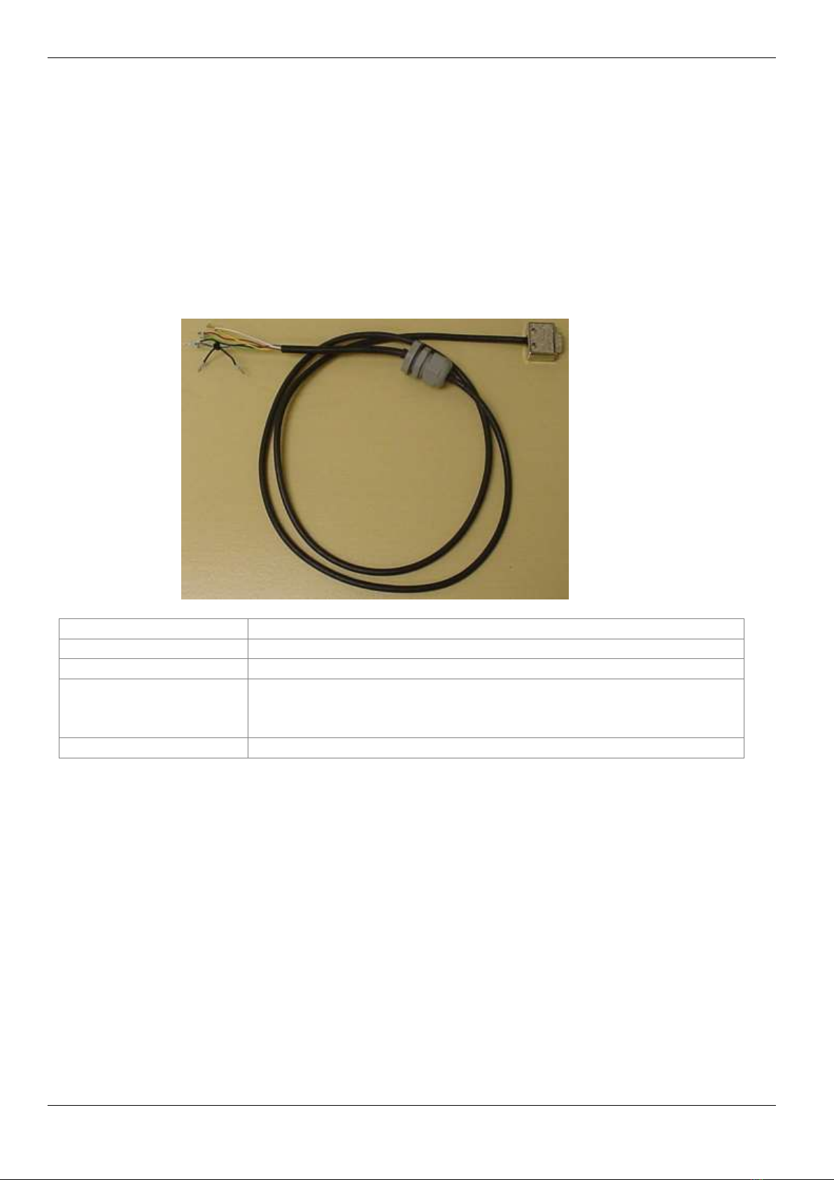
This Safety Interlock Cable is available from Voltech as an optional accessory for your tester and
requires the Banner EZ-Screen Safety Light Curtain System. It is designed so that it will not
compromise the speed of test and your throughput in production. It is based on a ‘light curtain’ of
infrared beams positioned in front of the tester. Once the operator has placed a transformer on
the test fixture, and removed his or her hand, the light curtain can signal that the situation is safe
within a few tens of milliseconds. However, if the operator tries to touch the transformer during
program execution, the safety system will open the safety interlocks (also within a few tens of
milliseconds), and stop any test that is running.
The infrared safety system is easy to install with no special tools or knowledge. Once installed, it
will be operational immediately, and will require the minimum of operator training
1.2. RECOMMENDED INFRA-RED SAFETY SYSTEM
For optimum safety, ease of use and test speed, Voltech recommends the use of a safety light
curtain with the AT5600 and other Voltech products that can generate dangerous voltages during
routine production testing.
This provides a ‘light curtain’ of infrared beams positioned in front of the tester.
Once the operator has placed a transformer on the test fixture, and removed his or her hand, the
light curtain can signal that the situation is safe within a few tens of milliseconds.
However, if the operator tries to touch the transformer during program execution, the safety
system will open the safety interlocks (also within a few tens of milliseconds), so that the tests
with dangerously high voltages will not be run.

VPN 98-121 ISSUE 3PAGE 5
The Safety Interlock Cable is an accessory that makes connection between the AT5600 and a
safety light curtain as safe and easy as possible.
The cable has been optimized for use with the ‘Banner’ safety light curtain described below, but
safety light curtains from other manufacturers may also be suitable.
To construct a complete safety system, you will need:
From Voltech
250-030 Safety Interlock Cable
From Banner
1 off ‘EZ-Screen’ safety light curtain
1 off EZAC-R9-QE8 AC Interface Box
Input Voltage: 100-250V ac
Input Frequency: 50-60Hz
Input Current: typical 0.37A @ 100V ac in
typical 0.23A @ 200V AC input
1 off SLPE14550AP8 Emitter (Silver) 550mm high with 100mm to 7.0m range.
1 off SLPR14-550P8 Receiver (Yellow) 550mm high with 100mm to 7.0m range.
1 off CSB-M1281M1281 “Y” Splitter Cord Set
1 off DEE2R-88D Male to Female Extender Cord Set
Source: www.bannerengineering.com
NOTES:
The Banner part numbers were correct in 2016
You are strongly advised to consult with your safety system supplier before making purchase
decisions.
Similar safety systems are available from many other manufacturers and may be suitable.

VPN 98-121 ISSUE 3PAGE 6
2 DESCRIPTION
2.1. GENERAL DESCRIPTION
The Safety Interlock Cable is a robust and convenient way of connecting the AT5600 and other
Voltech products to a safety interlock system.
Although other safety systems may be suitable, the cable has been optimized for direct and quick
connection to the Banner product described in the previous chapter.
Length
1.75 meters
Construction
High-quality shielded cable and terminations.
AT5600 Termination
Slimline 9-way d-type plug
Safety System
Termination
Color-coded wires with bootlace ferrules.
20mm cable gland to secure the cable to the light curtain control
box case.
Voltech Part Number
250-030

VPN 98-121 ISSUE 3PAGE 7
2.2 PRINCIPLE OF OPERATION
The cable carries 3 pairs of color-coded wires.
Each pair must be linked together by the safety system before the AT5600 will operate a high
voltage test.
If any one of the three pairs become un-linked during a test, the AT5600 very quickly switches off
any high voltage that is being produced.
There are three pairs of wires in order to provide the multiple redundancies required by various
international safety standards.
Yellow and Blue
The primary control (MPCE) elements of the AT5600. The primary generator power is passed
through the yellow and blue leads. The contacts used to connect yellow to blue must be rated
230V ac, 4A or more.
Black Link
This link may be used to series two primary control relays of the safety system. This provides
protection against one of the MPCE relays of the safety system locking in a closed position.
Red and White
This is the secondary control element (MSCE) of the AT5600. If this pair is open-circuited, prime
power will also be removed from the AT5600 high power generator. This action is independent of
the MPCE above and thus provides fail-safe operation of the complete safety system.
A 6k8 resistor is fitted in series with this pair, as required by the AT5600’s electrical control
system.
Green and Black
This is a monitoring pair, used by the AT5600 to confirm the status of the safety system.

VPN 98-121 ISSUE 3PAGE 8
2.3 CABLE SCHEMATIC
Function
AT5600
9-pin d-type
Safety Light Curtain
Connection to safety
system.
Primary power to
the high voltage
generators is
passed through
pins 3 and 7
3
Yellow
Main power-breaking
relays (Final Switching
Device) of the safety
system. The black link is
used to series 2 relays,
if required.
7
Blue
No Connection
Black
No Connection
Black
Secondary control
logic.
5
Green
Monitoring or auxiliary
relay.
6
Black
Secondary
switching device.
(A 6k8 resistor is
fitted in series with
pin 2).
2
Red
Secondary Control
Element.
9
White
Screen
Screen
No Connection

VPN 98-121 ISSUE 3PAGE 9
3 INSTALLING THE IR SAFETY SYSTEM
3.1. POSITIONING THE LIGHT CURTAIN
The light curtain should be positioned in front of the tester, extending well beyond the width of the
tester so that the operator is not impeded when he/she has to load and unload the transformer
under test.
The interconnection between each of the modules is via simple multi-way cables, which are easy
for you to install.
Finally, the AT Safety Interlock cable connects between the BANNER control box and the AT
Safety Interlock socket.
This document gives an overview of the Banner EZ-Screen functions when used with the
AT5600. In particular, it describes how to connect the cable to the BANNER control box.
The user must refer to the BANNER documentation for details of assembly and operation
of the Micro Screen
The following shows a suggested installation.

VPN 98-121 ISSUE 3PAGE 10
The dimensions are as follows
a =Width of the light curtain 1.8m to 2.0m
b =Banner cable length from control box to vertical columns b1 = 0.9m / b2 = 3.4m
c =Voltech cable length from control box to AT tester 1.5m
d =Lowest beam in light curtain 130mm minimum
e =Highest beam in light curtain 630mm maximum
g =Beam to edge of fixture 100mm minimum
The two vertical columns are equipped with suitable mounting brackets, making it easy for you to
secure them to the work surface in the correct positions either side of the AT series tester.
The length of the cables is sufficient to allow you to position the control box outside the safety
enclosure either under or on top of the work surface.

VPN 98-121 ISSUE 3PAGE 11
3.2. IMPORTANT - OPERATOR SAFETY
It is the responsibility of the user's organization to ensure that the AT5600 and its associated
safety systems are installed, maintained, and operated in accordance with all safety guidance
and legislation that may be in force locally.
The BANNER EZ-Screen (light curtain) will provide only part of the complete safety function that
is required. The AT5600 and light curtain must be installed by a designated, qualified safety
person who will conduct an overall assessment of the risks involved and provide operator
training, safety notices, and further safety equipment as well as install the AT5600 and light
curtain in accordance with local regulations.
When conducting a risk assessment and providing operator training and notices, it should be
noted that the first safety feature of the AT5600 is the yellow indicating light on its front panel.
This light will be lit when the AT5600 is running a test and may be generating dangerous
voltages. (External indicating devices can also be used to show that the AT5600 is in a
hazardous condition. See the 'Remote Port' description in the AT5600 user manual.)
The operator should not attempt to touch the part under test or enter the safety enclosure when
the yellow light is illuminated.
The light curtain then provides supplementary safety protection against accidental entry into the
safety enclosure by the operator.
3.3. IMPORTANT NOTE - THE SAFETY ENCLOSURE
Clearly, any safety system should be thought of providing a total ‘safety enclosure’ which
prevents access from all sides to the dangerous voltages on the transformer under test.
It is also clear that the infrared safety system can only provide one side of this safety enclosure -
that which faces the operator.
If there is a danger that an operator or any other person could touch the transformer under test
from either the side or the rear of the tester, then you must also take steps to prevent this, either
by installing suitable physical barriers, or for example, by positioning the tester in the corner of
the room so that existing walls prevent access to the transformer from the side and rear.
The two vertical columns of the IR safety system would then normally be placed touching the
physical barriers, which form the side-walls of the safety enclosure.
Additionally, it should be noted that highest beam in the light curtain of the IR safety system is
approximately 550mm above the work surface.
If there is any danger that the operator could reach over this height, or could touch the
transformer under test from above, then further precautions should be taken to provide physical
barriers to guard against this.

VPN 98-121 ISSUE 3PAGE 12
3.4. CONNECTING THE SAFETY INTERLOCK CABLE TO A BANNER LIGHT
CURTAIN
The following instruction has been written specifically for the BANNER EZ-Screen, Model
Number EZAC-R9-QE8 AC Interface Box
Caution:
Ensure that the light curtain and the AT5600 are disconnected from the mains supply line
before opening the control box. Failure to do so could result in personal injury.
Consult the user manual supplied with the light curtain for up-to-date information.
1) Voltech Safety Interlock Cable (250-030) preparation:
a) Cut the plastic tie-wrap joining the Blue wire and the Black jumper wire. The Black jumper
wire is not required for Banner Model Number EZAC-R9-QE8 installation.
Refer to Figure 1
Figure 1
b) Remove the Cable Gland supplied with the Safety Interlock Cable and replace with the cable
gland supplied with the Banner AC Interface Box. Do not tighten at this point. Refer to Figure 2.
Figure 2

VPN 98-121 ISSUE 3PAGE 13
2 Fit an AC Power Cord with the second cable gland supplied with the Banner AC Interface Box.
Do not tighten at this point. Refer to Figure 3
Figure 3
3)Remove the lid from the Banner AC Interface Box.
4) Identify the terminal block, P1, P2, and P5, inside the Banner AC Interface Box. Also identify
the EDM slide switch.
Model Number EZAC-R9-QE8.
5) Fit the cable gland for the AC Power Card onto the bottom hole of the Banner AC Interface
Box.
Connect the flying leads of the AC Power Cord to terminal block P5 inside the AC Interface Box.
Tighten the cable gland after connections are made. Refer to Figure 4
AC Power
Terminal Block P5
AC Power Cord Wire Color
Earth
1
Green-Yellow or Green
Neutral
2
Blue or White
Line
3
Brown or Black
Figure 4

VPN 98-121 ISSUE 3PAGE 14
6) Fit the two Shorting Links provided with the Banner AC Interface Box into terminal block P1 as
followed; Refer to figure 5B
a.) short X1 to X2 b.) short X3 to X4
Figure 5A Figure 5B
7) Set the EDM Slide Switch to 2-CH EDM position. Refer to figure 6.
Figure 6
8) Fit the cable gland for the Safety Interlock Cable onto the top hole of the Banner AC Interface
Box.
Connect the flying leads of the Safety Interlock Cable to terminal block P2 of the AC Interface
Box.
Tighten the cable gland after connections are made. Refer to Figure 7
Terminal Block P2
Safety Interlock Cable Wire Color
13
Yellow
14
Blue
23
Green
24
Black
33
Red
34
White

VPN 98-121 ISSUE 3PAGE 15
Figure 7
9) Replace the lid on the Banner AC Interface Box.
10) Connect the d-type connector to the AT5600’s interlock port (see Figure 8).
Figure 8
11) Position the AT5600, light curtain beams, control box and cables as described previously
12) Apply power to the light curtain control box and follow the manufacturer’s instructions for test
and use.
13) Apply power to the AT5600 and test the safety system as described in the next chapter.

VPN 98-121 ISSUE 3PAGE 16
14. Banner AC Interface Box, POWER light. Refer to Figure 9.
Figure 9

VPN 98-121 ISSUE 3PAGE 17
4 TESTING THE SAFETY SYSTEM
4.1. RECOMMENDED DAILY CHECK
Testing of the safety system, which may include checking any physical barriers in the total safety
enclosure surrounding the tester, should be supervised by your designated, qualified person
responsible for operator safety.
The following tests must be carried out during installation of the light curtain and at periodic
intervals, normally daily, as determined by the designated safety person:
1. Check the integrity of the complete safety enclosure including warning notices and
physical barriers.
2. Check that the light curtain columns, AC Interface Box, and cables are securely mounted
and free from damage.
3. Check that the inside faces of the two columns is clean and free from dust. If necessary,
wipe the beam windows with a clean, soft, damp cloth, taking care not to scratch the surface. Do
not use organic solvents or thinners to clean the windows.
4. Switch on the power to your safety system, making sure there is nothing between the two
columns. After a few seconds, the Banner AC Interface Box should be showing a green POWER
light, indicating that the light curtain is ready for use. If the Banner AC Interface Box shows a red
POWER light, then the light curtain must not be used. Perform the following checks in sequence,
checking for a green light each time:
•Clean the inside faces of the columns as above.
•Make sure there are no obstructions between the columns during switch on.
•Check that the columns have not moved out of alignment.
•Check for changes in the lighting environment - reflective surfaces, dust or very strong
sunlight can disrupt the beams.
5. When the Banner AC Interface Box is showing a green POWER light, then the IR beam
detectors should be tested to be fully functional:
•Use the test rod to break the infrared beams between the two columns. Insert the test rod
at 90° to the beams and move it slowly from top to bottom in three places: midway between the
columns and close to each vertical column. The POWER indicator on the Banner AC Interface
Box will show red at all points while the test rod is in the beams.
•Repeat the same procedure with the test rod inserted at 45 degrees to the beam.

VPN 98-121 ISSUE 3PAGE 18
4.2. QUICK CHECK – COMPLETE SYSTEM
The above process will check the action of the light curtain on its own.
To check the operation of the complete system (i.e. to confirm that the interlock signals are
correctly understood by the AT5600) you can use the interlock icon on the display of the AT5600.
Repeat the above tests with the rod and observe the Icon on the front panel of the AT5600.
Light Beam NOT INTERRUPTED Light Beam IS INTERRUPTED
AT5600 Interlock icon is GREEN AT5600 Interlock icon is RED
Test programs WILL execute Test programs WILL NOT execute
If any part of the operation is not correct, or if you suspect that the safety system is not operating
properly for any reason, stop working and carry out detailed checks as described in this and the
safety system manuals.

VPN 98-121 ISSUE 3PAGE 19
5 OPERATING THE AT5600 WITH THE IR SAFETY SYSTEM
For a description of the use of the Light Curtain with the AT5600, please see the AT5600 user manual
(98-119) chapter 6.
Chapter 6.5 describes the operating and warning messages that may be observed on the AT5600
when it is being used with a safety light curtain.

VPN 98-121 ISSUE 3PAGE 20
6 CONSTRUCTING SAFE FIXTURES
As described in the previous section, when the light curtain of the safety system is broken, the
tester will stop the execution of a high voltage test, and remove the dangerous voltages, to
protect the operator from the dangers of electric shock.
This may sound a simple operation, but in fact it is not.
Firstly, there has to be a certain amount of signal processing within the vertical columns to detect
that the IR beams have been broken.
Secondly, the control box has to signal this to the tester.
Thirdly, the tester has to ramp-down the test source.
This final operation has to be done carefully, because if there is current flowing through the
inductance of a winding and it is suddenly switched off, rather than creating a safe situation, it
could produce a dangerously high ‘back EMF’.
Clearly this means that, after the light curtain has been broken, there has to be a finite amount of
time to switch off and safely ramp down the potentially dangerous voltage. With the IR Safety
System, this time could be as long as 50msec.
This time has to be born in mind when you are designing your test fixtures. It is essential that
any high voltage point on the transformer under test is set far enough back from the light curtain
so that it cannot be touched by the operator’s hand within 50msec of breaking the beams.
Note that the high voltage points on the transformer could include the body or core (as well as
terminals) if your program contains Hi Pot tests for core isolation.
The normally assumed value for the speed of an operator’s hand is 2m/sec.
This speed implies that the distance from the beams of the light curtain to the dangerous point on
the transformer should be at least 100mm.
Table of contents
Popular Cables And Connectors manuals by other brands

Tyco Electronics
Tyco Electronics ACO Single Port Kits instruction sheet

PCB Piezotronics
PCB Piezotronics IMI SENSORS 009M205/100 Installation and operating manual

Reinhausen
Reinhausen c.a.p.t. 099 Series Installation manual & maintenance

Griven
Griven AL4750 instruction manual

Tellur
Tellur TLL321031 user manual

Philips
Philips SWV2802W Specifications