VOLTEQ RX Series User manual

HIGH POWER PLATING RECTIFIER
USER MANUAL
VOLTEQ

1
Please read the user manual carefully before operating this rectifier.
Warning: Do not connect any load to the rectifier before it's turned on. Likewise, make sure to
disconnect the load before shutting down the rectifier. Damages to the rectifier may occur if you do not
follow this. Such damages are not under warranty.
Warning: If you are running inductive load like magnetic coils, DC motors, stepper motors, etc.,
make sure to change the voltage/current slowly, and NEVER turn the rectifier on or off with a inductive
load connected!
Warning: Do not attempt to inspect or repair the rectifier unless it has been powered off for at least
one minute.
Warning: The copper wires/terminals maybe be hot after the rectifier has been turned on.
Warning: Vapors from plating tank can be corrosive to the electronic components, damages caused
by corrosion is not under warranty.
I. Overview

2
RX series plating rectifiers are high power rectifiers with reverse polarity capability. These
rectifiers can be operated in forward and reverse polarity manually or automatically with built-in timer.
The rectifiers have high efficiency, high output, and are designed for continuous operation. The
rectifiers have built-in over current, over voltage, and over temperature protection. They can act as
constant voltage as well as constant current DC rectifier. These rectifiers are great choice for
wastewater treatment (electrocoaguation), hard chromium plating, stripping, electrochemical treatment,
and other applications that require high output power. The table below lists the standard models
available from Volteq.
Model Output
Voltage
Output Current AC Voltage Maximum AC
Current
HY10500RX 0-10V 0-500A AC220V±10%
50/60Hz
30A
HY15200RX 0-15V 0-200A AC220V±10%
50/60Hz
20A
HY30200RX 0-30V 0-200A AC220V±10%
50/60Hz
35A
Volteq also makes a range of custom rectifiers with output up to 10,000A and 500V, with or without
polarity reversal; please inquire at support@volteq.com.
3
II. Control Box Layout and Specifications
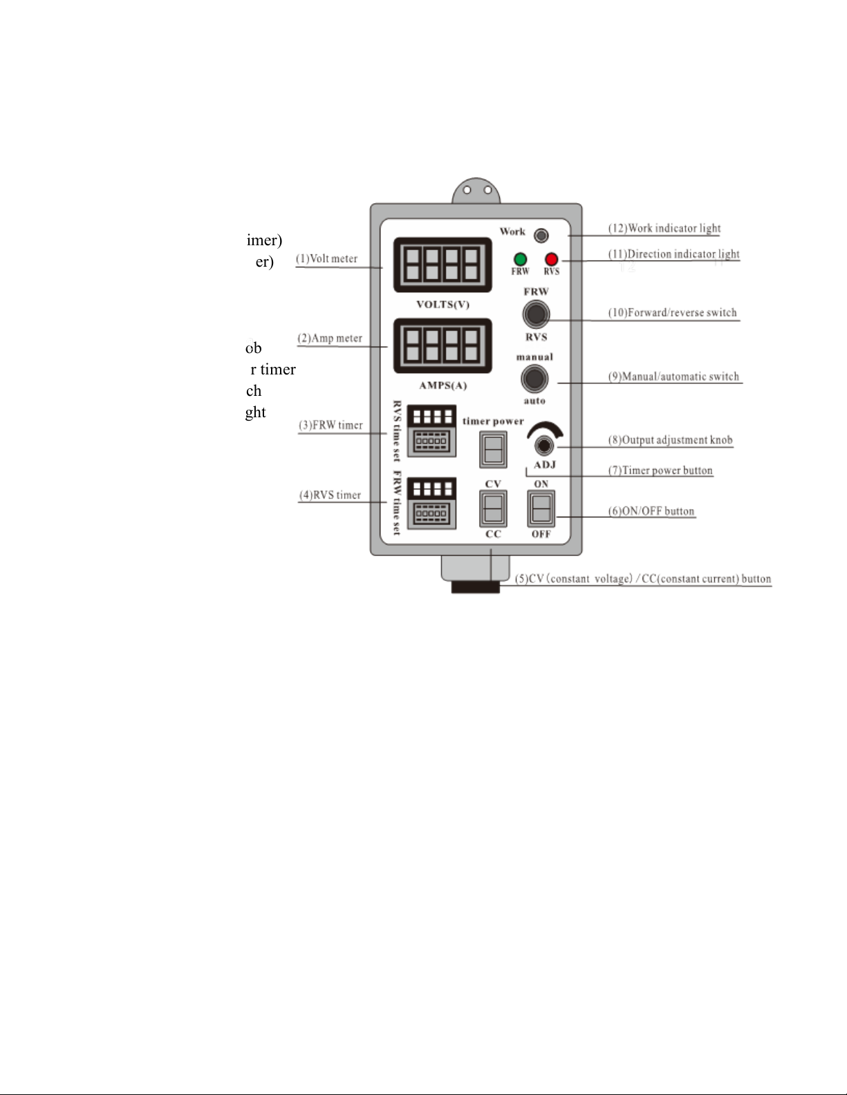
2.1 Control box layout
(1) Volt meter
(2) Amp meter
(3) FRW timer (forward timer)
(4) RVS timer (reverse timer)
(5) CV/ CC switch
(6) ON/OFF Switch
(7) Timer power button
(8) Output adjustment knob
(9) Manual/auto switch for timer
(10) Forward/reverse switch
(11) Direction indicator light
(12) Work indicator light

4
2.2 Technical specifications
Ripple and noise: ≤5%
Voltage regulation: ≤0.5%
Current regulation: ≤1%
Load regulation: ≤0.5%
Display accuracy: ±1%±1 digit
Control accuracy: ≤1%
Protection: Over-current, Over-voltage, Over-temperature
Input voltage: AC220V±10% 50/60Hz
Working conditions: -10oC –40oC, relative humidity<90%, no condensation
Storage conditions: -20oC-80oC, relative humidity<80%
Ventilation: minimum of 50cm of open space around the rectifier is required for good ventilation
Elevation: ≤1500 Meters
Timer: separate timer for both directions between 0.01 second and 99 hours and 99 minutes

5
III. Operating Procedures for Reverse Polarity Control
3.1 Manual versus auto mode
3.1A Manual mode
Shift switch (9) to up position to enter the MANUAL mode.
In manual mode, shift switch (10) to select the output polarity you need, indicator light (11) shows
the corresponding polarity. Press button (7) to OFF to disable automatic timer function. The output will
run continuously.
When button (7) is switched to ON position, the output is controlled by the timer. If the FRW state
is selected, power supply will output in the forward direction, until the FRW timer expires. When the
timer expires, power supply shuts down automatically and with no voltage/current output. Likewise, if
the RVS state is selected, power supply works in reverse mode. It shuts down automatically when the
RVS timer expires.
3.1B Auto mode
Shift switch (9) to bottom position to enter into AUTO mode. In auto mode, the switch (10) is
non-functional. The rectifier begins with forward mode always; when the FRW timer expires, it
automatically enters the reverse mode and starts the RVS timer countdown. After RVS timer expires, it
automatically enters the forward mode. If button (6) is in ON state and timer power button (7) is in ON

6
state, the cycle will continue forever, until operator stops it. If the power supply is ON and timer power
is in off state, it will stay in the forward mode, and hold its run mode without expiration.
[Note: the auto/manual switch (9) and FRW/RVS switch (10) have three positions, namely,
"ON-OFF-ON". Shift to up/bottom position, do not shift to middle position, otherwise the equipment
will not work normally.]
3.2 Operating procedures
1) Check to ensure the AC plug is secure and wired correctly for the polarity. Check to ensure the
output is connected correctly and securely.
2) Check to ensure the button (6) is in OFF state, and the work indicator light (12) is off; turn the
output adjustment knob (8) counter-clockwise to the minimal position.
3) Plug into AC outlet, and then turn on the main power of the rectifier, Check to make sure the fan is
working normally.
4) Select switch (5) to either "CV" or "CC" as your operating mode. If "CV" is selected, the output
voltage will be stable while the output current will change with the load; likewise, if "CC" is
selected, the output current will be stable while the voltage will change with the load.
5) According to the requirements of your process, shift switch (9) to select the mode you need, see
section 3.1 for more details.
6) Press button (7) to the state as you want. If timer power is in OFF state, timer function will not work;

7
if timer power is in ON state, set the FRW timer and RVS timer per your process requirements.
Each timer can be set separately within the range of 0.01 second to 99 hours and 99 minutes.
There are total 5 positions to set. The middle position determines whether the timer is on hours (h),
minutes (m), or seconds (s). The two digits to the left are in the units you select, and the two digits
on the right are decimal or in units below, e.g., if m is selected, you can set timer to 0-99 minutes
using the two digits to the left, and 0-99 seconds using the two digits to the right.
Mid switch position h m s
Timer duration 1m-99h99m
1s-99m99s 0.01s-99.99s
[Note: The timer must be set before start of the run. When the power supply is in
ON state, the cover of timer should not be opened to change the setting.]
7) Connect the load securely to the copper bars in the back.
8) Shift switch (6) to ON position, Timer will start.
9) Adjust knob (8) to set the output to the desired level.

8
IV. Maintenance
Routine inspection and maintenance is required for prolonged working life of the rectifiers:
1) Regularly check to ensure the power supply is in dry condition. If moisture is found inside the
power supply, dry it off immediately before further usage by blowing dry air into it, or take it to dry
off in the Sun for a couple of hours.
2) Clean dust off the inside of the rectifier and cooling fan.
3) Clean off the oxide layer that may occur on the output copper wires and connectors.
4) Check to ensure that cooling fan is in good working condition all the time; replace the fan if needed.
5) Regularly check and ensure that switches and circuit breaker are in good working condition and all
connectors are secure and firm.
6) The rectifier should not sit idle for more than a year, as the capacitors may change its characteristics
if not charged for a long time.

9
V. Troubleshooting
Symptoms Possible Cause
Indicator light flashes, no voltage output There maybe a short between output terminals
Fan may not be working properly or the
rectifier may have over-heated
Over-current protection maybe trigged
Voltage output is normal, but no current output Connection to the positive and negative
terminals maybe loose
Circuit breaker jumps during operation Some components may have failed internally
Output voltage or current is not stable Voltage or current meter may have gone bad
Case is not grounded and is electrically hot The environment maybe too humid
Some internal components may have failed
The timer clock is not correct Timer failure; replace timer.
Automatic reverse polarity does not work
Check to ensure the manual/auto switch is in
AUTO
Check to ensure timer power button ON.
If both are OK, then the timer needs to be
replaced.
Polarity does not change when FRW/RVS switch Check to ensure the manual/auto switch is in

10
is shifted MANUAL state.
Check to ensure FRW/RVS switch is in
correct position.
FRW/RVS switch might be at fault; replace
the switch.
Power supply might be at fault, call tech
support.
FRW or RVS Indicator light does not work Indicator light might be at fault; replace
indicator light.
Power supply might be at fault, call tech
support.
Timer function doesn’t work Check to ensure the timer power button is in
ON state.
Timer might be at fault; replace timer.
All products from Volteq come with 1-year full manufacturer's warranty. For technical questions or
warranty service, please contact us at support@volteq.com or call us at 408-622-9851.
This manual suits for next models
3
Other VOLTEQ Power Supply manuals


