Smart-Fly PowerExpander Sport User manual

CHARGING CAUTION:
Because there are two batteries that each connect to a
common point this creates a situation called “Common
Ground” meaning the two battery’s grounds are
ALWAYS connected, even if you use a switch on each
battery. Virtually every charger on the market cannot
handle a Common Ground situation. If you try to
charge both batteries at the same time (using either one
charger with multiple outputs or two chargers) you risk
damaging the batteries, the charger or both. This can
be dangerous with Li poly batteries. To charge both
batteries at the same time, the circuit must be broken to
break the Common Ground.
Servo Power LEDs
The servo power LEDs are next to the XT-30 connectors and indicate
power is present on that connector. These do not indicate the voltage
input is above the minimum required.
Receiver Power LEDs
The receiver power LEDs show the receiver is getting voltage greater
than .75V. If the receiver regulator output voltage drops below .75
volts the LEDs will go out. There are two possible causes of the
receiver voltage going below .75 volts. First the load the receiver is
presenting to the regulator is greater than one amp causing the regulator
output to droop. This could be caused by directly plugging something
into the receiver that is overloading the circuit. The second cause of
the receiver regulator going below .75 volts is the input voltage to the
receiver regulator has dropped below 5.10 volts. This means the input
voltage on the XT-30 connectors is probably below 5. 5 volts for some
reason.
Optional Failsafe switch
The PowerExpander Sport supports the addition of a failsafe switch
(optional package). When using the failsafe-switch, the switch lead is
plugged into the input marked “Sw” near the top right of the servo
connections as shown on the reference drawing.
Smart-Fly can supply two types of failsafe switches. First is the
standard slide switch that most people are familiar with. This is a small
slide switch with out a charge jack. The second failsafe-switch is the
Pin & Flag switch, where a pin, with a flag on it, is inserted into the
switch to turn the system off. To fly, the pin is pulled out of the switch.
The advantage of the Pin & Flag switch is that the system cannot
accidentally be turned off, as can be the case with a slide switch. The
failsafe switch lead can be extended using a standard Futaba extension.
The PowerExpander Sport also supports charging the batteries through
the two charge connections denoted by the “C”, one on the top of each
servo output rail as shown on the reference drawing.
The charge jacks on the PowerExpander Sport can also be used to
connect to a battery meter. One thing to keep in mind when using a
battery meter and the failsafe-switch is that the jacks are not switched
off when the unit is off so the battery meter will continue to draw
power even when the unit is turned off.
Additional information and technical help can be found at
www.Smart-Fly.com
Quest Engineering & Development, Inc.
6125 South Ash Avenue, Suite B-8
Tempe, AZ 85283
Ph: (480) 460-2652 Fax: (480) 460-2653
P
Po
ow
we
er
rE
Ex
xp
pa
an
nd
de
er
r
S
Sp
po
or
rt
t
U
Us
se
er
r
G
Gu
ui
id
de
e
Thank you for purchasing the Smart-Fly
PowerExpander Sport!
This manual takes you through the installation and operation of the
Smart-Fly PowerExpander Sport. The features of the PowerExpander
Sport are:
• For up to 60cc 3D or up to 75cc IMAC or Scale
• Light weight, 1.4oz, 54g
• Compact design, footprint is 2.6” x 3.5”
• Battery input voltage up to 8.4V
• Inputs protect against cell failure or power shorts
• Filtered and regulated 5.0V power to the receiver
• LED power indicators for input and receiver power
• Fully buffered outputs on all channels
• Full filtration of all signals in and out of the unit
• Can be used with optional failsafe switch
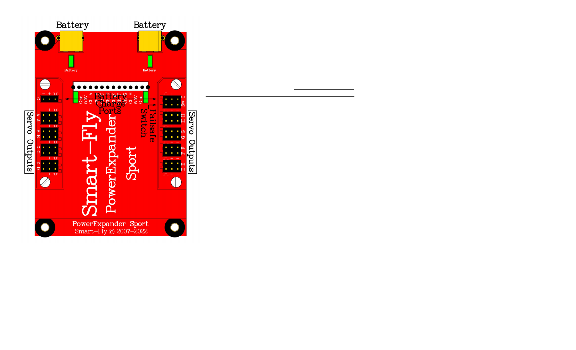
Reference Drawing
Receiver Mounting
The receiver mounts in the center of the unit. 3M dual-lock mounting
tape has been supplied to mount the receiver. This tape’s holding
power is extremely strong. It is recommended that the whole 1”x2”
piece not be used, instead cut some 1”x ½” strips and use these on
either end of the receiver.
We also have available an “L” shaped receiver mount that will mount
the receiver at a sixty degree angle and get the antenna(s) up, away
from the unit. While we have not found this to be necessary for
2. GHz receivers with long antennas (Futaba, Hitec & Airtronics)
which extend past the end of the unit it will possibly help JR and
Spektrum 2. GHz receivers that have short antennas on the main
receiver. The receiver mount will get the antennas up off the unit
towards the canopy.
Receiver Connections
CAUTION: Do not plug any receiver pigtails into the battery input
of your receiver UNLESS the battery input is also a servo channel
(i.e. receiver shares channel 8 and battery for example). On PCM
it will put your receiver into DSC mode, on 2.4GHz receivers it
may cause your receiver to unbind. All connections from the
PowerExpander are meant to plug into servo outputs ONLY.
The receiver servo outputs are connected to the pigtails coming out of
the PowerExpander Sport in the area with the notations “Ch A” through
“Ch H” on the reference drawing. The two channels on the end (“Chan
A” and “Chan H”) have power connections to the receiver in addition
to the signal connection. If you have a receiver that has less than 8
channels, you should still use both the end connections as this will
provide you with power redundancy to the receiver in the event that a
power or ground lead should fail.
The unit will accommodate both end-loading receivers and top-loading
receivers. All signals from the receiver into the PowerExpander Sport
are RF filtered. This prevents noise from the servos entering the
receiver connections to the receiver. If all channels are not going to be
used, then the unused pigtail can be tucked away.
All channels have two servo outputs each. The channels of the
PowerExpander Sport can be used on any receiver channel, the
PowerExpander channels do not have to connect to the receiver in any
order. Most pilots will connect the PowerExpander channels to the
receiver channels so that the servo wiring is neat. Typically servos on
the left side of the plane come off the left side of the PowerExpander
and servos on the right side of the plane come off the right side of the
PowerExpander. In addition you want to be sure the PowerExpander
channel has an adequate number of servo outputs.
Other Device Connections Directly To Receiver
If you want to connect a device directly to the receiver instead of going
through the PowerExpander Sport, make sure the current draw of the
the device is less than twenty milliamps or so. We recommend you do
not connect servos directly to the receiver. There are several reasons
that a device might be connected directly to the receiver instead of
going through the PowerExpander Sport. The most likely would be if
you had a fourteen channel receiver and needed to use the extra
channels. Items such as jet ECUs and smoke pump control do not draw
much current and could be used.
Servo Connections
Servos are connected to the PowerExpander Sport along the two rails
on either side of the receiver. The servo connectors are universal in
that they will work with Futaba or JR connectors. When using a JR
connector, be careful to observe the polarity of the connection. The
ground lead (black on Futaba, brown on JR) is indicated by the “minus”
sign, the positive power lead (red on Futaba and JR) is indicated by the
“plus” sign and the signal line (white on Futaba, orange on JR) is
indicated by the “top hat” symbol.
All receiver channels have each servo signal output individually
buffered. If a servo were to short its signal wire, the other servos on
that channel would not be affected.
The unit also RF filters each signal output and matches line impedance
resulting in a cleaner signal down long servo leads. The impedance
matching reduces the electrical “ringing” that can occur on long servo
leads. Ringing can generate RF interference and can reduce receiver
range.
Power Connections
This unit’s inputs will tolerate voltages up to 8. V (lithium-ion or
lithium-polymer 2-cell packs). The power inputs are protected from
each other in case of a dead cell or short. There is about 0. volt drop
between the input and the servos under a 12 amp load on each battery.
If lithium packs were used the servos would see about 8.0V for fully
charged packs under a 12 amp load. For A123 packs this means that
after they flatten out at 6.6V the servos will see about 6.2V under a 12
amp load..
CAUTION: Input voltage to the PowerExpander Sport should be
at least 5.7V. This is due to the 0.40V drop across the “BatShare”
and the 0.35V diode drop plus the 0.35V dropout voltage of the
receiver regulator to maintain a 5.0V output to the receiver.
It is highly recommended that you use two battery packs for
redundancy and to provide extra current to the unit. Power is supplied
to the unit through the two XT-30 connectors. Since this is not a
common connector at this time we provide 2 XT-30 female connectors
so you can change your battery connector or make an adapter. We also
sell adapters for common battery plugs (UltraPlug, XT-60, etc) with an
XT-30 female on the other end.
Popular Power Supply manuals by other brands

Videx
Videx 520MR Installation instruction

Poppstar
Poppstar 1008821 Instructions for use

TDK-Lambda
TDK-Lambda LZS-A1000-3 Installation, operation and maintenance manual

TDK-Lambda
TDK-Lambda 500A instruction manual

Calira
Calira EVS 17/07-DS/IU operating instructions

Monacor
Monacor PS-12CCD instruction manual


