VOLTEQ HY1550EX User manual

REGULATED DC POWER SUPPLY
USER MANUAL
SINGLE OUTPUT SWITCH MODE DC POWER SUPPLY

Please read this manual carefully before operating the power supply.
1. Introduction
Volteq HY series single output switch mode DC power supplies are regulated variable DC power supplies
designed to provide the most often required DC outputs in scientific and research institutions, schools and colleges,
industrial R&D, as well as manufacturing and testing.
The output voltage is continuously adjustable between 0 and the rated voltage by means of the coarse and fine
potentiometers; the output current is continuously adjustable between 0 and the rated current by means of a current
adjustment knob. Both outputs are accurately displayed on the digital voltmeter and ammeter.
The DC power supplies in this series have high efficiency, superior load and line regulation, and low ripple noise.
These power supplies have high level of protection including over voltage, over temperature, and over load protection.
They can act as constant voltage as well as constant current sources. Because of the excellent protection, these power
supplies are widely used for electroplating, anodizing, electroforming, electro-winning, battery charging and
equalizing, and other applications requiring excellent reliability and robustness.
2. Specifications
2-1 General
AC Input 110V/220V, 110V, or 220V ±10%, 50/60 Hz
Rating See table 2-1
Operating environment: Indoor use with dry and dust-free air for cooling
Altitude: up to 2000 m

Temperature: -10°C to 40°C
Relative humidity: <80%
Table 2-1
Model Max. Voltage
Max. Current
Fuse Type and
Rating
Input AC
50/60Hz
Weight (lbs)
HY1550EX 15V 50A 15A/250V 110V/220V 15
HY15150EX 15V 150A air switch 110V or 220V 23
HY3050EX 30V 50A air switch 110V/220V 16
HY3080EX 30V 80A air switch 110V or 220V 21
HY30100EX 30V 100A air switch 110V or 220V 23
HY5030EX 50V 30A air switch 110V/220V 16
HY5050EX 50V 50A air switch 110V or 220V 21
HY7520EX 75V 20A air switch 110V/220V 17
HY7530EX 75V 30A air switch 110V or 220V 20
HY10010EX 100V 10A 15A/250V 110V/220V 15
HY10020EX 100V 20A air switch 110V or 220V 21
HY12010EX 120V 10A 15A/250V 110V/220V 15
HY12020EX 120V 20A air switch 110V or 220V 21
HY20010EX 200V 10A air switch 110V or 220V 21
HY30005EX 300V 5A air switch 110V/220V 17
HY15020EX 150V 20A air switch 110V or 220V 23

2-2 Front Panel Descriptions
(1) Trademark and Model #: shows Volteq as trademark and the actual model number of the power supply.
(2) Digital ammeter: displays the actual output always; this equates to the set value if in CC mode.
(3) Digital voltmeter: Displays the actual output voltage always; this equates to the set value when in CV mode.
(4) Current knob (Fine): for fine adjustment of current limit.
(5) Current knob (Coarse): for coarse adjustment of current limit.
(6) Voltage Adjustment (Fine): for the fine adjustment of the voltage limit.
(7) Voltage Adjustment (Coarse): for the coarse adjustment of the voltage limit.
(8) OV Adjustment: for setting the OV (over-voltage) level (See 3-5) with a flat head screwdriver (not included).

(9) CC indicator light: this indicator turns red when the power supply is in constant current (CC) mode (See 3-2).
(10) OV indicator: this indicator turns red when the power supply is over-voltage protected. The power supply will not
respond to user control until it's reset (See 4-2 for more details).
(11) Over-temperature (OT) indicator: this indicator turns red when the internal temperature of the power supply is too
high, and the power supply output is disabled. See 4-3 for more details.
(12) CV indicator: this indicator light turns red when the power supply is in constant voltage (CV) mode (See 3-2).
(13) On/Off Power button: When this button is pushed to "In" position, the power supply is turned on; conversely, the
power supply is off when this button is in the "Out" position.
Note: For models with air switch, this button enables/disables the output. Turn the air switch on first before
turning this button on; conversely, turn this button off before switching off the air switch in the back. For
the models without air switch, this button turns the power on and off.
(14) Front output terminals: from left to right, labeled as negative, ground ("GND"), and positive. The output is
between the + and - terminals, while the ground terminal is for grounding the case only. To reduce the ripple, the
negative output terminal ("-") is usually shorted with “GND”. Only select models include the front terminals.
Warning: the front terminals are rated for less than 10A only. Use only the rear output terminals if output
current is more than 10A, and tighten the connection to reduce contact resistance.
Warning: For electrochemical applications (e.g., plating and anodizing), remove the short connector between
“–” and ground terminals.
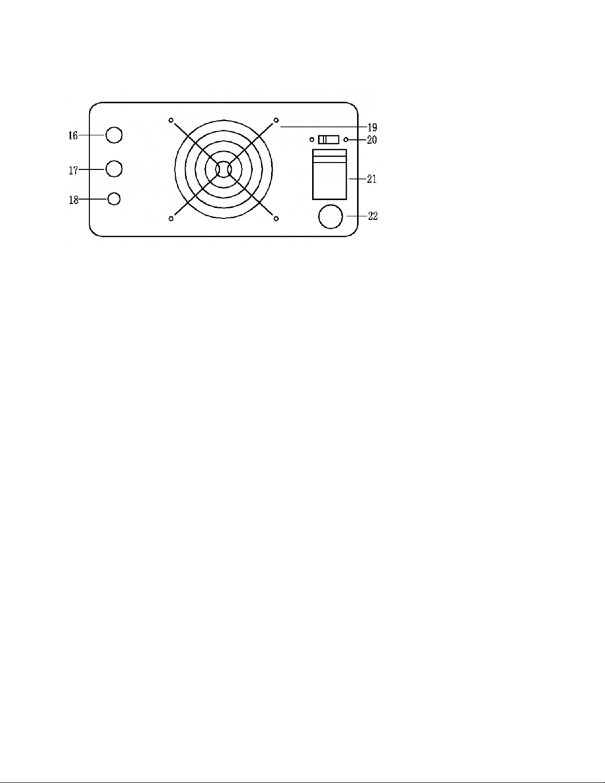
2-3 Back Panel Descriptions
(16) Positive Terminal.
(17) Negative Terminal.
(18) Ground Terminal: this is connected to the case.
(19) Cooling fan: the fan is turned on briefly when the power supply is energized; afterwards it is turned on when
internal temperature of the power supply rises above 45℃.
(20) AC voltage selector switch: use this switch to select the input AC of either 110V or 220V for select models.
(21) Air Switch: the resettable air switch is available for select models only.
(22) AC Input. For power supply models not equipped with air switch, the fuse is located here. To replace the fuse,
remove the AC power cord, and use a flat head screwdriver to remove the fuse holder.

Warning: To avoid electrical shock, the power plug ground pin must be connected to AC ground.
Warning: the voltage indicated on the power supply must match the AC voltage, otherwise the power supply
will be damaged (plugging a power supply rated for 110V into 220V AC), or the maximum output would
not be reached (plugging a 220V power supply into 110V AC). Damage caused by plugging into wrong
AC voltage is not under warranty.
2-3 Technical Parameters
1) Voltage stabilization: ≤0.2%
2) Current stabilization: ≤0.5%
3) Load stabilization: ≤0.3%
4) Ripple and noise: ≤1%( RMS)
5) Display accuracy: ±1%±1 digit
3. Operation Instructions
3-1 Installation
1) Before plugging into AC outlet
The input voltage of the power supply is typically shown on the top rear part of the case. AC voltage should be within
10% of the input voltage specified, e.g., if the specified input voltage is 110V, the power supply will work with AC

voltage of 110V±10%.
Warning: The voltage indicated on the power supply (look for a sticker on the case close to the rear) must
match the AC voltage, otherwise the power supply will be damaged (plugging a power supply rated for
110V into 220V AC; such damages are not under warranty), or the maximum output will not be reached
(plugging a 220V power supply into 110V AC). If the power supply is equipped with an AC voltage
selector switch in the back, the selector switch must show the correct value in the middle, e.g. for 120V
AC, the switch itself should show 110V in the voltage selector switch as shown in picture below:
Warning: Changing the AC voltage selector setting must be done with the power supply unplugged from AC.
Warning: To avoid electrical shock, the power cord ground conductor must be connected to AC ground.
Warning: Do not connect a load to the power supply before it's turned on. Likewise, disconnect the load before
shutting down the power supply. Shutting down improperly can cause the power supply to fail when it’s
turned on next time. Damages due to improper startup and/or shutdown are not under warranty.
Warning: When running an inductive load like magnetic coils, DC motors, stepper motors, etc., make sure to
set the output to zero before connecting the load, change the voltage/current slowly, and NEVER turn the

power supply on or off with a inductive load connected!
2) Installation: For better heat dissipation, the two sides and back of the power supply should have at least 10cm space
from the walls. The cooling fan is controlled by thermistor and will turn on automatically when the temperature of the
heat sink is above 45°C. The power supply comes with over-temperature (OT) protection, and will disable itself when
the inside temperature of the device is too high. The power supply resets itself once the temperature falls below the
40°C. To ensure proper operation, make sure the ambient temperature is below 40°C and there is sufficient ventilation.
3-2 Constant Voltage / Constant Current Characteristics
The power supply is a regulated constant current / constant voltage (CC CV) power supply, which is characterized by
automatic crossover from constant current (CC) to constant voltage (CV), and vise versa. At any moment, the power
supply automatically determines whether to operate in CV or CC mode, depending on the voltage and current limit (set
by the front knobs), and the load connected (if no load is connected, it simply means that the load resistance is infinite;
conversely, if a short is connected, the load resistance is zero).
Note: The power supply is in CC mode if indicator light 9 is red; it’s in CV mode if indicator light 12 is red.
In order to understand the crossover, it is important to note that the voltage and the current are related by the Ohm’s
law, so only one of the two is an independent variable. The law dictates that the output current I in amps (A) is always
equal to the output voltage V in volts (V) divided by the load resistance R in ohms (Ω):

For example, if the load resistance (R) is such that the current limit (set by knobs 4 and 5) is higher than the
voltage limit (set by knobs 6 and 7) divided by R (i.e., voltage limit is lower than current limit for the load R
connected), the power supply operates in the constant voltage (CV) mode. When in CV mode, the output voltage
remains constant even if the load resistance changes (e.g., if load resistance decreases, the current increases), up to the
point when the preset current limit is reached. The crossover point is reached when the voltage and current limit are
reached simultaneously. Beyond the crossover point, the indicator changes from CV to CC, and the current limit
becomes the lower limit, and the output current remains constant and the output voltage drops in proportion to the
further decrease of the load resistance.
Similarly, crossover from constant current (CC) to constant voltage (CV) mode automatically occurs when the
resistance of the load is increased. A good example of this behavior is charging a 12V lead acid battery. Initially, the
open circuit voltage of the power supply may be set at 13.8V. A discharged battery when connected to the power
supply may demand high charging current beyond the current limit set for the power supply (or the maximum current
capacity of the power supply), and the power supply will operate in constant current mode, with the maximum
charging current equal to the set current limit. As the battery becomes more charged, the voltage will increase, and
eventually reach 13.8V. Beyond that point, the current demand from the battery will drop and fall below the set limit.
The crossover is signaled by the indicator light changing from CC to CV.

3-3 Operating Procedures
a) With the power switched off, leave the OV limit (8) to maximum position (factory default) or adjust per
instructions at 3-5.
b) Make sure that the AC line voltage matches the input voltage of the power supply.
c) Make sure there is no load connected, plug power cord into the AC outlet.
d) Turn the power supply on.
Caution: For models with air switch, the green On/Off button enables/disables the output. Turn on the air
switch first before turning this button on; conversely, turn this button off before switching off the air
switch in the back. For the models without air switch, this button turns the power on and off.
1) Constant Voltage (CV) Operations
e) Adjust current knobs (knobs 4 or 5) to slightly above zero so that CV indicator light is on, and set voltage
(knobs 6 and 7) to the desired output voltage.
f) Connect the external load to the output terminals. Make sure both "+" and "-" terminals are connected
correctly. For output more than 10A, you must use the rear terminals.
g) Turn the current knobs to maximum to ensure that the power supply stays in CV mode. If it’s necessary to
limit the current while operating in the CV mode, follow section 3-4 first to set the current limit.
h) Once finished, turn the current down to < 1A, disconnect the load, and then turn off the power supply.

2) Constant Current Operation
e) Adjust current knobs (knobs 4 or 5) to slightly above zero so that CV indicator light is on, adjust voltage
control (knobs 6 & 7) to set voltage to the desired voltage limit (this is the maximum voltage you want to
operate at). If charging a battery, set the voltage to the normal charging voltage recommended by the battery
manufacturer.
f) Connect the external load to the output terminals. Make sure both "+" and "-" terminals are connected
correctly in terms of polarity. For output more than 10A, you must use the rear terminals.
g) Turn the current knobs slowly up until you reach the desired current level. Make sure CC light is red.
h) Once finished, turn the current down to < 1A, disconnect the load, and then turn off the power supply.
3) Battery Charging Operation
Warning: at no time should the battery be connected to the power supply when the power supply is turned off, or
with the output voltage of the power supply set to lower than the battery voltage.
Warning: Before the battery is connected to the power supply, make sure that the power supply output voltage is
set to higher than the battery voltage. If the power supply gets into OV protected mode or AC power is
lost, remove the battery immediately from the power supply. For this reason, we do not recommend you
to set OV level to maximum position.
e) If the maximum allowed charging current for the battery is lower than the maximum rated current of the
power supply, set the current limit following instructions in section 3-4. Use a magic marker to mark the

position of the coarse current knob (knob 5). Otherwise, skip this step.
f) Turn the coarse current knob to minimum position or slightly above zero while still keeping the CV light on.
Use knobs 6 and 7 to set the voltage to desired charging voltage recommended by the battery manufacturer.
g) Stop the output, then connect the battery while making sure that the polarity is correct (+ to + and – to –).
Disconnect the battery immediately if you made a mistake. For output > 10A, you must use the rear terminals.
Warning: damage caused by wrong polarity is not under warranty.
h) Enable the output, then turn the coarse current knob up to the marked position, or the maximum position if it’s
safe to charge at the maximum output of the power supply. If the CC light is on, adjust this knob slightly to
make sure the current meter is reading the maximum charging current. If the CV light is on, it simply means
that the battery is not depleted enough to charge at the maximum current allowed.
j) Watch the charging progress, when the current is below 1A or 1/10 of the maximum charging current, it is
probably time to stop. Make sure the AC power never goes off line during the charging process.
k) Stop the output, disconnect the battery from the power supply, and then turn off the power supply.
4) Inductive Load
Warning: it is critical to change the current on the inductive load slowly. Sudden changes of power supply
output can cause the inductive load to generate a reverse EMF much larger than the voltage from the
power supply, and cause damage to the power supply. Turning on or off the power supply with an
inductive load connected can cause power supply to fail beyond repair. Damages like this are not under

warranty.
e) Adjust all 4 knobs (both current and voltage) to minimum position.
f) Connect the external load to the output terminals. Make sure both "+" and "-" terminals are connected
correctly. For output more than 10A, you must use the rear terminals.
g) For CV operation, turn the current knobs to maximum position. Slowly turn up the voltage until it reaches
desired voltage level. For CC operation, turn the voltage knobs to maximum. Slowly increase the current until
it reaches the desired current level.
h) Once finished, slowly turn down either the current or voltage knobs until the output is zero before
disconnecting the load. After the load is disconnected, it is safe to turn off the power supply.
3-4 Setting Current Limit for CV Operation
Note: this step is only needed if it is necessary to set a current limit for constant voltage operation; for most of
applications requiring constant voltage, simply turn the current knobs 4 & 5 to maximum position, which
basically sets the current limit to the maximum value allowed by the power supply.
1) With no load connected, turn all 4 knobs to minimum position. Turn the power supply on.
Caution: For models with air switch, the green On/Off button enables/disables the output. Turn on the air
switch first before turning this button on; conversely, turn this button off before switching off the air switch
in the back. For the models without air switch, this button turns the power on and off.
2) Connect a resistive load between + and – terminals, or temporarily short the + and – terminals of the power supply

with a test lead with sufficient thickness.
3) Adjust the COARSE voltage knob (knob 7) slightly up so that the CC indicator turns red.
4) Adjust the CURRENT control (knobs 4 & 5) to reach the desired current level, repeat 3) if needed.
5) The current limit has now been preset. Do not change the CURRENT knobs (4&5) if you want to keep the same
current limit, or mark the positions of the knobs 4&5 so you can return to the same level.
6) Turn the voltage knobs down so that the current meter reads less than 1A, then remove the load between the ( + )
and ( - ) terminals and go to section 3.3(1) for CV operation procedures.
3-5 Setting Over-voltage Protection Limit
The power supply has over-voltage protection with adjustable protection limit.
Note: For most applications, we recommend setting the OV limit at maximum (factory default setting), which is
typically 2V above the maximum rated voltage. To return to factory default, turn the OV adjustment screw
to the maximum position clockwise (8). You must do so before turning the power supply on.
For very sensitive applications, it maybe desirable to set OV level to a specific value, by following the steps below:
1) Determine the maximum voltage allowed by the your application (the OV limit). This should be slightly
higher than the operating voltage. If for whatever reason there is a voltage surge above this limit (measured at
the output terminals), the OV light will turn red, and the power supply will no longer respond to user input
(with the output turned off). For easier communication, we assume that 12.0V is the working voltage and
13.0V is the OV limit.

2) With no load connected, make sure the OV level (8) is set to maximum. Turn the power supply on.
3) Use knobs 6 and 7 to adjust the voltage to 13.0V; adjust current knobs if necessary to stay in CV mode.
4) Slowly turn the OV adjustment (8) counterclockwise, stop as soon as the OV light turns red. The OV limit is
set at 13.0V now.
5) To reset the power supply, turn the knob 6 and 7 counterclockwise to minimum position, and turn the power
supply off.
6) Once the power supply is completely off, turn it back on, and set the voltage to 12.0V. Note that if voltage is
set to higher than 13.0V, the OV protection will kick in.
4. Trouble Shooting & Maintenance
Warning: The following instructions are to be performed by knowledgeable personnel only. To avoid electrical
shock, do not perform any servicing other than the contained in the operation instructions. For further
questions, please contact factory support at support@volteq.com.
4-1 Fuse Replacement
Some models are equipped with air switch, which is a reset-able breaker and does not require a fuse. The rest of the
models are equipped with a fuse. If the fuse is blown, the power supply will not turn on. It is a good idea to determine
and correct the cause of the blown fuse, then replace only with a fuse of the correct rating and type. The fuse is located

on the rear panel where power cord is plugged into the device, as shown to the right:
Warning: For continued fire protection, replace fuse only with fuse of the specified type and rating. All
replacement fuses must be slow-blowing type.
4-2 Rest OV Protection
When OV light is red, the power supply is in OV protected state, and will not respond to user input until the power
supply is properly reset. To reset the power supply, follow the procedures below:
1) Disconnect the load and turn the power supply off.
2) Turn the OV limit (8) to the maximum position clockwise; or leave it to the correct setting if you have already
set it up properly.
3) Turn the voltage knobs down (knob 6 & 7).
4) With no load connected, turn the power supply on. The power supply is reset and ready to be used.
4-3 Recovery from Over-temperature Protection
If the internal temperature is too high, the power supply is disabled due to over-heating, and the OT indicator turns red.
When this happens, disconnect the load; correct the cause of the over-heating, and the power supply will recover

automatically. Typical cause of over-heating includes:
1) Not enough ventilation due to space limit.
2) Ambient temperature is too high.
3) The cooling fan stops working.
4) Output exceeds the rated range.
Caution: the power supply can be operated at the maximum outputs (both current and voltage) for less than 15
minutes. For continuous operation, either the voltage or the current should be below 80% of the
maximum rated value.
Special Note: Model HY5030EX comes with reverse voltage protection, OT light turns red when it’s connected
to a source like battery with the wrong polarity. If this happens, disconnect the load immediately. None of
the other models described in this manual has reverse voltage protection, and the power supply will be
damaged if connected to a battery with wrong polarity.
5. Warranties and Attachment
User manual 1
Power cord 1
Warranty: this product is covered by standard one-year manufacturer’s warranty, which includes parts and
labor for one year from the date of purchase.
This manual suits for next models
15
Table of contents
Other VOLTEQ Power Supply manuals


