Volvo 960 User manual

Volvo Car Corporation
Göteborg, Sweden
Installation instructions, accessories
850 / 960 / C70 / S70 / V70 (-00)
S60 / V70 (00-) / V70 XC (01-) / S80 / S90 / V90
Section Group Weight (Kg/Pounds) Year Month
3 39 2000 04
CD-box (in the glove compartment)
© Volvo Car Corporation, 2000 Printed in Sweden 9172614

A0000162 A0000163
M8802509 M8802108
S8802511 S8802510
S8802521
2000 04 9172614

1
A8901294
2A
A8800034
2B
A8502171
2C
A8502172
2D
A8502246
2E
A8502247
2F
D8502541
3A
A8502174
2000 04 9172614

3B
A8502175
3C
A8502173
3D
A8502252
4A
M8503103
4B
D8502540
4C
M8503104
2000 04 9172614

5
A8502176
6
A8502462
7
A8502463
8
A8502464
2000 04 9172614

English
INTRODUCTION
•NOTE! Read through the entire text before carrying
out any work.
•The front page gives the date of this editionandtheedition
it replaces
•The second page shows the tools needed for the
installation and the contents of the installation kit
•The illustrations display the procedure in order of operation.
The order of operation is repeated in the text section
•Cut out the text page in order to follow the illustrations and
text at the same time.
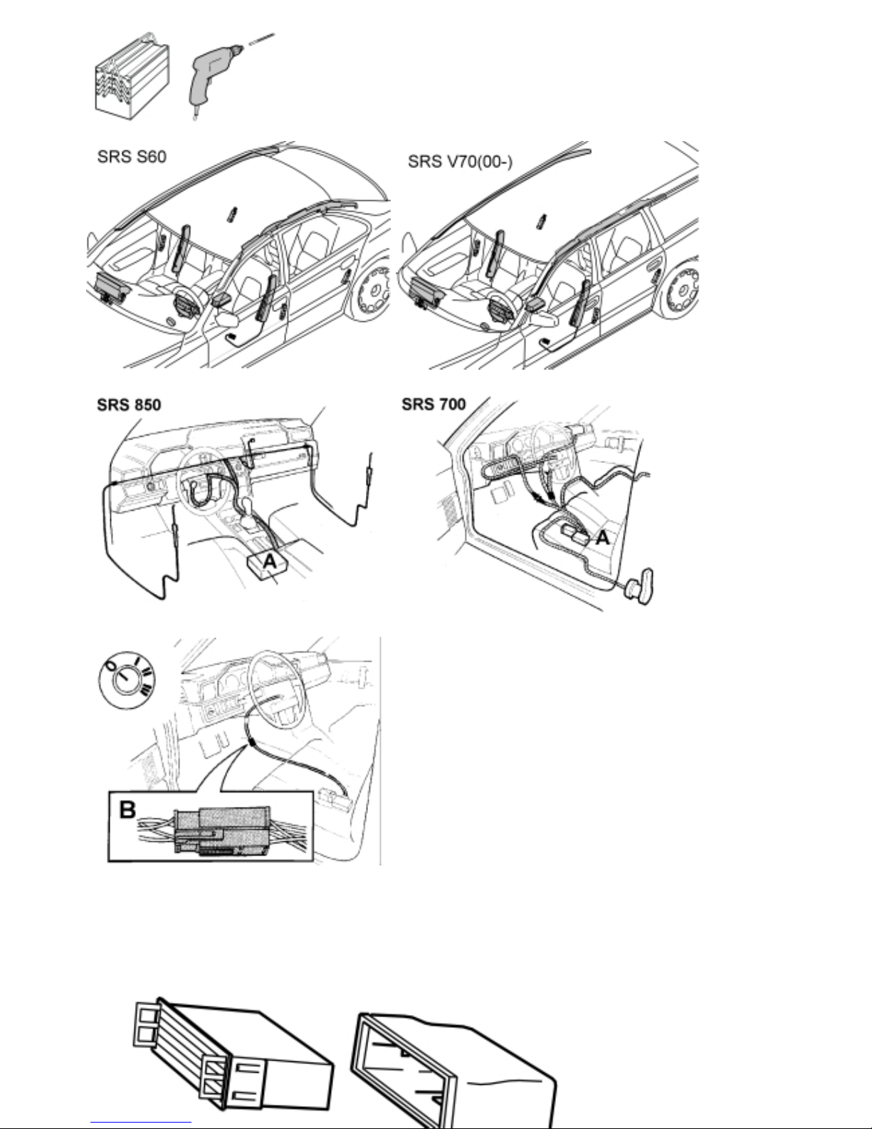
Cars equipped with SRS/SIPS (Airbag)
WARNING! Extracaremustbetakenwhe
n working on
cars equipped with SRS/SIPS air bags. Thisisimportant
to prevent:
1. Personal injury
2. Damage to or malfunction of the SRS/SIPS system.
Work on the SRS/SIPS systems or related components
must be carried out by an authorised Volvo workshop.
Is the car equipped with SRS/SIPS?
Cars with SRS are most easily recognised by the letters SRS
on the steering wheel pad. If the car also has an airbag on
the passenger side, the letters SRS are embossed on the
dashboard above the glove compartment. SIPS decals are
located on the seat panels and the windscreen.
Do not damage the SRS wiring!
Do not trap, fray, pierce or damage the SRS wiring. SRS
wiring has orange casing and/or is plaited.
Steering and front suspension
The contact reel in the SRS system can easily be damaged
when working on the steering wheel, steering shaft or steering
gear. Refer to the SRS Service Manual for information on
carrying out such work. This is to prevent damage.
SRS warning lamp
If the SRS warning lamp lights after repairs have been carried
out, take the car to an authorised Volvo workshop.
SRS collision sensor control module
S60 / V70 (00-) / S80
The collision sensor control module is located on the
transmission tunnel in the centre console, beside the parking
brake. The air bag inflation areas must not be obstructed.
Never place any objects, such as upholstery, within these
areas. The panels must be abletoopeninthecorrectway
and at the right time.
WARNING!
The ignition must be in position "0" and the key removed
from the ignition if any connector in the SRS system is
to be disassembled. Then wait at least five minutes.
Then disconnect the battery negative lead before
disassembling any of the connectors.
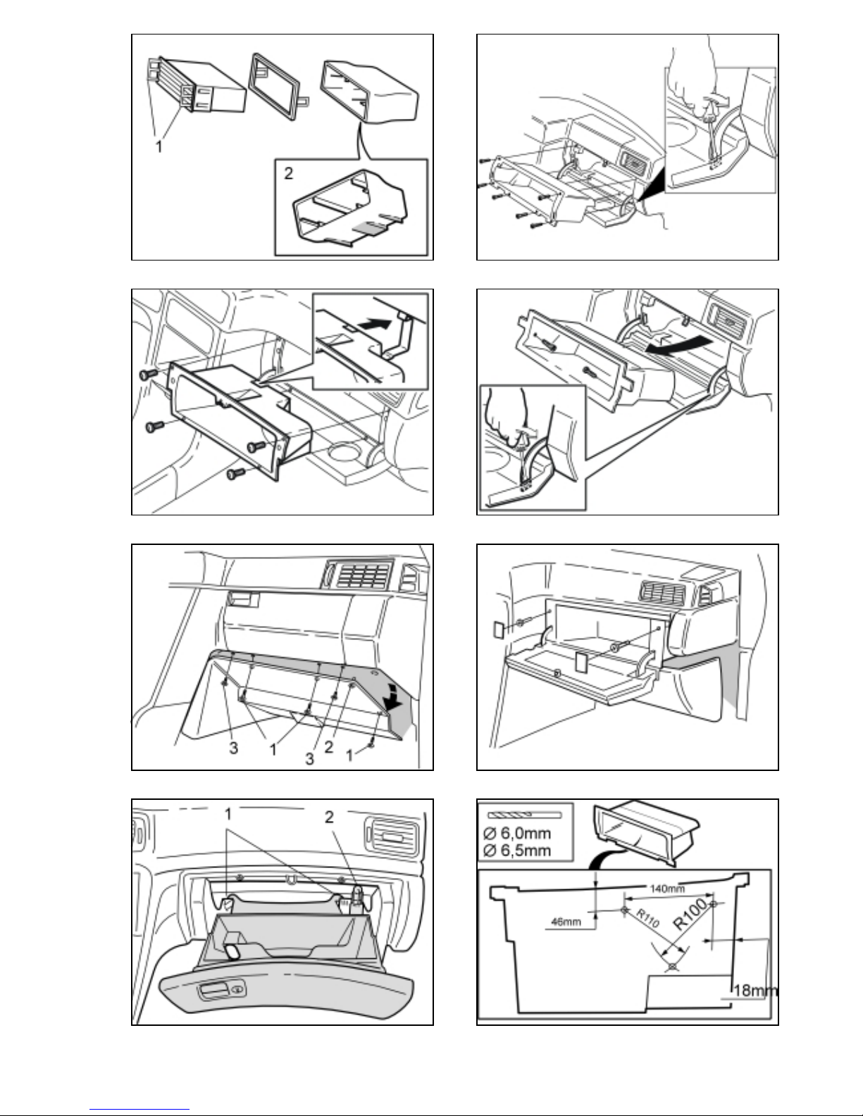
CD box (in the glove compartment)
Preparations
1– Separate the CD-bracket, the frame and the CD
holder. Release the circlips (1) on the CD holder.
Installing in the glove compartment
2Illustration A applies to the 850
Illustration B applies to the C70, S70 and the V70 (-00)
Illustration C applies to the 960, S90 and the V90 with
passenger side airbags
– Open the glove compartment.
– Remove the holders for the cover for the glove
compartment.
– Remove the screws from the glove compartment. Pull
the glove compartment out.
Illustration D and E applies to the 960, S90 and the
V90 without passenger side airbags
– Remove the screws (1).
– Remove the clip (2).
– Remove the screws (3).
– Remove the trim cover and the screws.
– Remove the glove compartment by pulling the glove
compartment to the right and backwards.
Illustration F applies to the S60, V70 (00-) and the S80
– Open the glove compartment.
– Carefully pull the catches (1) backwards until they
release.
– Pull off the spring holder from the upper mounting (2).
2000 04 9172614

3Applies to the 850, C70, S70, V70(-00), 960, S90
and V90
Illustration A applies to the 850
Illustration B applies to the C70, S70 and the V70 (-00)
Illustration C applies to the 960, S90 and the V90 with
passenger side airbags
Illustration D applies to the 960, S90 and the V90
without passenger side airbags
– Measure as illustrated and mark up for holes on the
underneath of the glove compartment.
– Drill out the holes. Use a Ø6 mm (15/64“) drill bit.
– Position the CD bracket in the glove compartment so
that the guides are against the bottom of the glove
compartment.
– Mark the holes on the CD bracket using the drilled
holes in the glove compartment as a guide.
– Drill out the holes in the CD bracket. Use a Ø6 mm
(15/64“) drill bit.
– Remove the CD bracket.
– Drill out the holes in the glove compartment. Use a
Ø6.5 mm (1/4“) drill bit.
4Applies to the S60, V70 (00-) and the S80
Illustration A
– Measure and drill holes in the glove compartment.
Use a Ø5 mm (13/64“) drill bit.
Illustration B
– MeasureanddrilltheholeintheCDstoragebox.Use
aØ5mm(13/64“)drillbit.
Illustration C
– Position the CD storage box in the glove compartment.
Install a rivet as a guide by hand. Do not rivet into
place.
– Hold the opening of the CD storage box parallel with
the edge of the glove compartment. Drill the next hole
in the CD storage box using the glove compartment
as a template.
– Install a rivet by hand in the new hole. Do not rivet
into place.
– Drill the last hole in the CD storage box using the
glove compartment as a template.
– Remove the CD storage box.
5Install:
– the glove compartment.
– the CD bracket in the glove compartment. Use the
supplied clips.
– the frame on the CD bracket.
– the CD holder in the CD bracket. Ensure that the
covers for the CD compartment on the CD holder
hang downwards at the open position. Press in the
catches (1).
Applies to the S60, V70 (00-) and the S80
– Clean the mating surfaces.
– Rivet the CD storage box and the glove compartment
together.
–Installtheframe.
– Install the CD compartment. Press in the catches (1)
(see illustration 2F).
– Install the spring holder (2) in the upper mounting (see
illustration 2F).
– Close the glove compartment.
Installing in the centre console
6Applies to the 960 S90 and the V90
– Measure as illustrated. Mark up for holes in the inside
of the CD bracket.
– Drill out the holes. Use a Ø6 mm (15/64“) drill bit.
7– Position the CD bracket in the centre console.
Position the guides towards the driver’s seat.
– Use the CD bracket as a drilling template. Drill a hole
using a Ø 6 mm (15/64“) drill in the centre console
compartment. Use a 6 mm (15/64“) drill stop.
– Remove the CD bracket. Drill out the hole in the
centre console using a Ø 6.5 mm (1/4“) drill bit. Use
a 3 mm (1/8”) drill stop.
8– Install the CD bracket in the centre console using the
supplied clips.
– Install the frame on the CD bracket
– Install the CD holder in the CD bracket. Press in the
catches (1).
2000 04 9172614
Other manuals for 960
2
This manual suits for next models
9
Table of contents
Other Volvo CD Player manuals