the accelerator panel, slacken off the two Torx screws and then pull the panel
free from the clips on the outer edges and unhook it
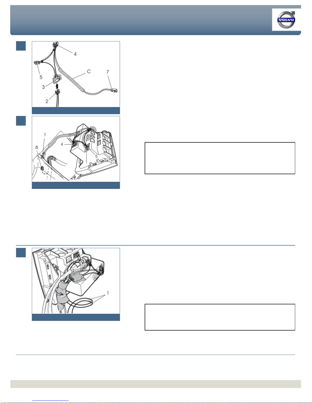
●Connect the connector (5) to the remaining connector (6) on the junction cable
●Take half of the foam tape from the wiring kit and wrap it around the grey
connectors (5, 6). Use the remaining foam tape to tape around the connectors
(3, 4).
Note!
The junction cable must be routed around the bracket as illustrated. When
reinstalling the bracket in the centre console in the car, the junction cable must
be held against the bracket as illustrated. This is to ensure that it remains in
position.
Routing and connecting wiring
Applies to cars without a factory installed player, when installing both a
MiniDisc and CD player/changer
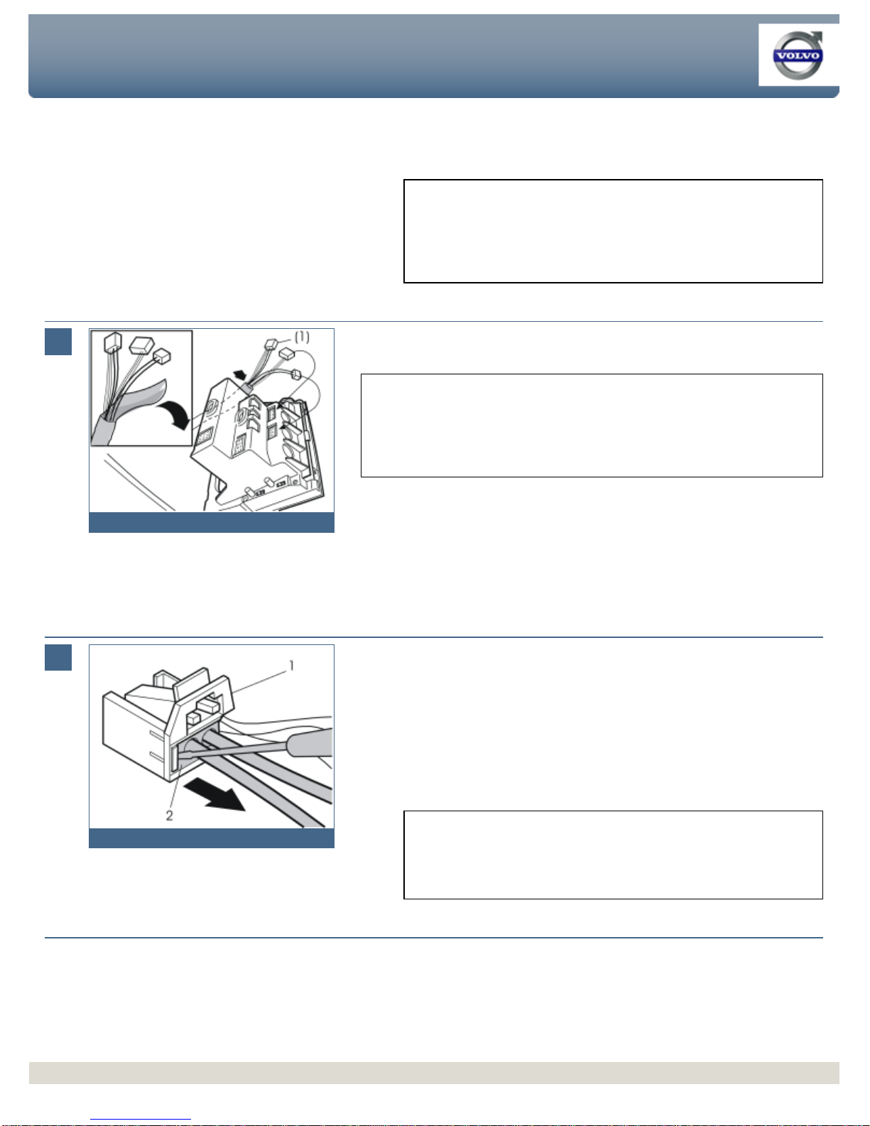
●Take out the junction cable (B) (purchased separately) with the four connectors
●Connect the connector (1) on the junction cable to the corresponding connector
on the MiniDisc player and connector (2) to the corresponding connector in the
CD player/changer. The connectors (1) and (2) are identical. It does not matter
which connector is connected to which unit.
●Locate the pre-routed, bridge connector (3) on the fibre optic cable in the centre
console, wrapped in foam tape
●Disconnect the connector (4) from the bridged connector (3). Connect it to
connector (5) on the junction cable.
●
Find the pre
-routed grey connector (6) for power supply in the thick cable
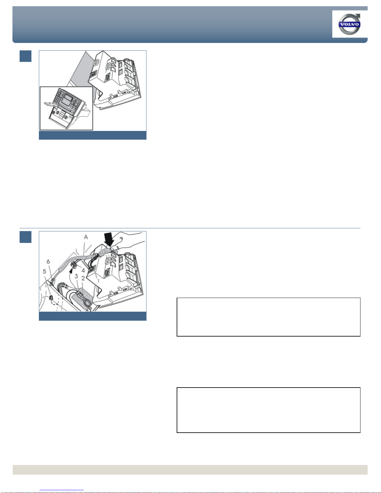
harness in the centre console. The connector is located either in the centre
console or in the space above the accelerator pedal. To remove the panel above
the accelerator panel, slacken off the two Torx screws and then pull the panel
free from the clips on the outer edges and unhook it
●Connect the connector (6) to the remaining connector (7) on the junction cable
Note!
Be very careful when connecting the connectors in the MiniDisc/CD players.
The terminal pins in these connectors are thin. They are easily damaged and
may become pressed into the players if the connector is not installed straight.
Note!
If installing a CD player and an RTI system at the same time, the junction cable
for the RTI system must be connected first to the connector (4). This connector
will then be in use, but there is a corresponding connector on the junction cable
for the RTI system. Connect this to the connector (5).
Installation instructions, accessories
-
CD player/changer (6 CD)
Volvo Car Corporation G
öteborg, Sweden
Installation instructions, accessories
-
CD player/changer (6 CD)
Volvo Car Corporation G
öteborg, Sweden
©
VolvoCar Corporation, 2002 Printed in Sweden
©
VolvoCar Corporation, 2002 Printed in Sweden
Page 8 of 11