VORAGO REB1 User manual

REB1 USER MANUAL
Evaluation board for VA108x0 MCU from VORAGO
FEBRUARY 10, 2017
VORAGO TECHNOLOGIES

VA10800/VA10820 Evaluation Board User’s Manual
V3.0
1
Contents
1 Introduction ............................................................................................................................ 2
1.1 Purpose of Document ..................................................................................................... 2
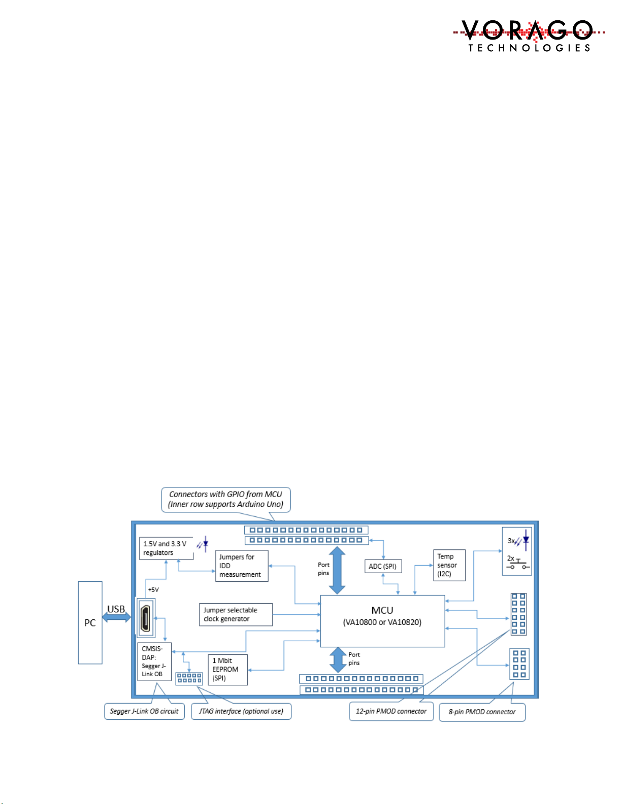
1.2 Overview of Hardware and Software components ........................................................ 2
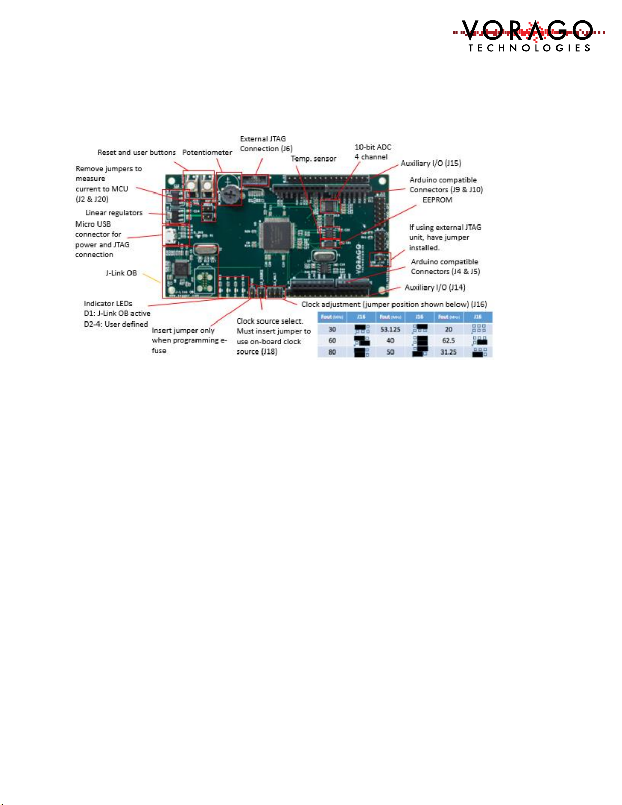
1.3 REB1 board component placement diagram.................................................................. 3
1.4 Connector pin assignment table..................................................................................... 3
1.5 Materials List................................................................................................................... 4
1.6 Support............................................................................................................................ 4
2 Software Setup........................................................................................................................ 4
2.1 Required Downloads....................................................................................................... 5
3 Hardware check ...................................................................................................................... 9
3.1 Powering up the board ................................................................................................... 9
4 Starting an IDE and building a program.................................................................................. 9
4.1 Keil IDE –......................................................................................................................... 9
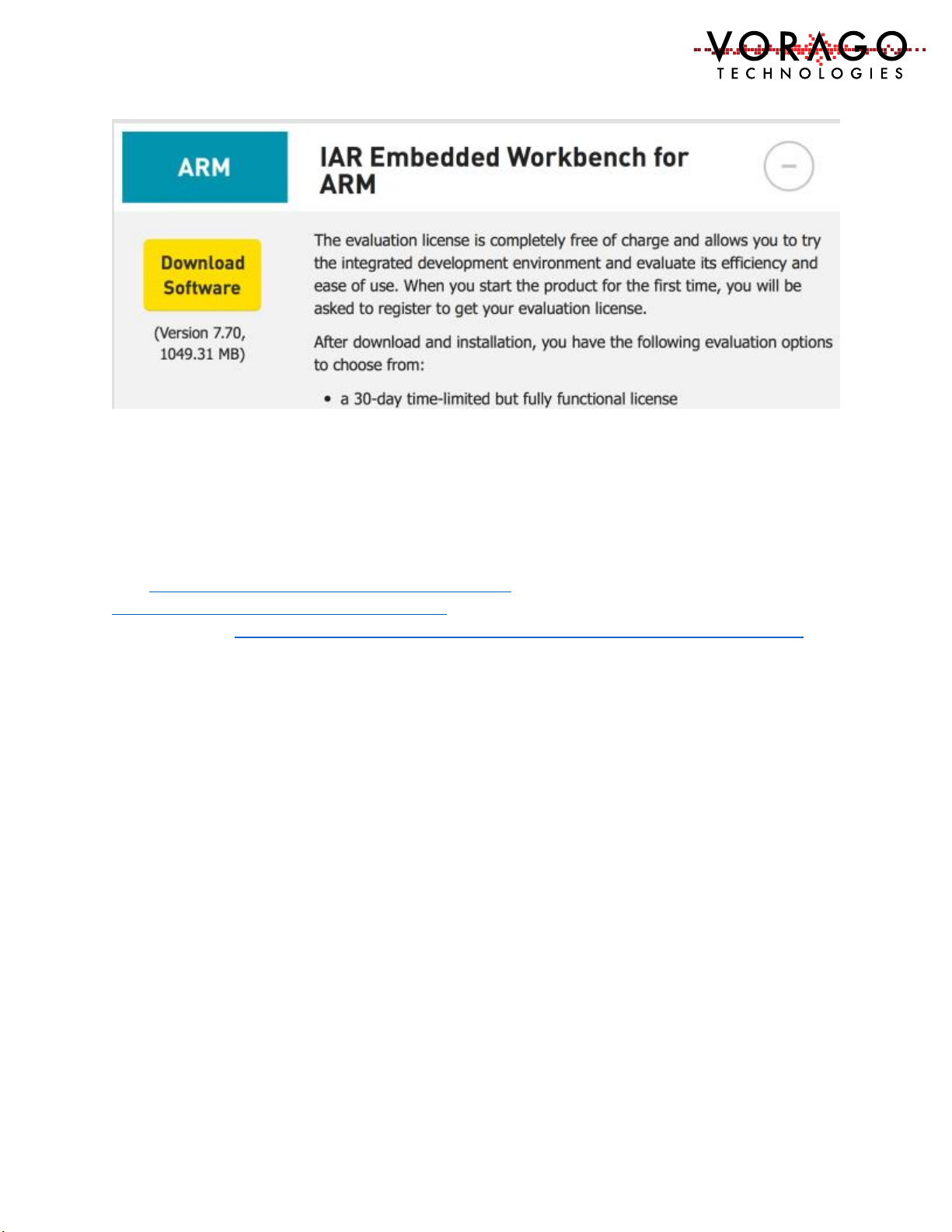
4.2 IAR EWARM IDE –.......................................................................................................... 18
4.3 iSYSTEM winIDEA IDE –................................................................................................. 21
4.4 J-Link OB and RTT (Real Time Terminal) ....................................................................... 25
4.5 Programming procedure (Keil Specific) ........................................................................ 26
5 Software Development Kit.................................................................................................... 28
5.1 Project organization...................................................................................................... 28
5.2 CMSIS compatible driver............................................................................................... 29
5.3 Preprocessor directives................................................................................................. 30
6 Lab exercises ......................................................................................................................... 30
6.1 Lab 1 –Toggling an output pin to blink an LED ............................................................ 30
6.2 LAB2 - Advanced input pin filtering and debounce of switch input. ............................ 32
7 Commonly asked questions .................................................................................................. 32
8 Other resources for VA108x0 code....................................................................................... 33
9 Revision history..................................................................................................................... 33

VA10800/VA10820 Evaluation Board User’s Manual
V3.0
2
1Introduction
1.1 Purpose of Document
This document is intended to provide instructions on how to use all features of the REB1
evaluation board and provide a working platform for software development with either the
VA10800 or VA10820 MCUs from VORAGO. The VA10820 has supplemental EDAC (error
detection and correction) and memory scrub functionality. In all other ways, the two devices
are register set identical.
1.2 Overview of Hardware and Software components
The REB1 evaluation board includes a JTAG interface from Segger known as J-Link OB. There is
no need for a separate JTAG debug pod although a connector is provided if a different tool is
preferred. SEGGER Microcontroller is a full-range supplier of hardware and software
development tools. The J-Link OB allows the board to be connected directly to the USB port of
a PC to allow:
-Power to be supplied from the USB 5V supply
-JTAG communications for debug and programming
-Terminal communications to allow data transfer between a PC terminal window and
the VA108x0 MCU.
A block diagram of the evaluation board is shown here. The intent of the board is to provide
sufficient hardware to evaluate all facets of the MCU at room temperature.
Figure 1 - Block diagram of REB1

VA10800/VA10820 Evaluation Board User’s Manual
V3.0
3
1.3 REB1 board component placement diagram
Figure 2 - Photo of REB1 with functional blocks identified
1.4 Connector pin assignment table
The schematic for the board is one of the included files in the REB1 software download
package. To assist with quickly finding which pins are tied to the various connectors on the
board, the following set of tables are provided.

VA10800/VA10820 Evaluation Board User’s Manual
V3.0
4
Table 1 - REB1 Connector designations
1.5 Materials List
•REB1 evaluation board –Programmed with demonstration program
•36” Micro USB cable
•Insert card with component placement picture and URL
•7 jumpers.
1.6 Support
Email: in[email protected] Reference REB1 in the email title.
2Software Setup
Three sets of software will be working in concert:
-Integrated Development Environment (IDE) {Either Keil, IAR or iSystem},
-Segger J-Link RTT viewer and
-Embedded code running on the VA108x0 processor.
The IDE allows code to be developed, compiled, debugged and programmed to an SPI EEPROM
on the board. The J-Link RTT Viewer allows terminal communication between the PC and the
VA108x0 MCU. Keys pressed on the keyboard can be routed to the VA108x0 MCU and printf

VA10800/VA10820 Evaluation Board User’s Manual
V3.0
5
statements from the VA108x0 MCU can either be logged into a file or shown on a terminal
window. See Figure 3 - Software interaction for REB1.
Figure 3 - Software interaction for REB1
2.1 Required Downloads
The following downloads are required to allow full functionality of the evaluation board. These
tools are evaluation versions and are free of charge. Three IDE options are provided. Only one
IDE is needed. Please download one IDE, the Segger J-Link software and the VORAGO REB1
software development code as outlined in the below sections.
2.1.1 Keil 𝜇Vision Integrated Development Environment
Keil offers an evaluation version of the IDE for free that will support compiled code of 32kbytes
and below. http://www.keil.com/arm/mdk.asp (approximately size = 400 Mbytes)

VA10800/VA10820 Evaluation Board User’s Manual
V3.0
6
Please use the default directories for the “core” and “pack” when prompted for information
during the install.
Before the MDK install is complete, the pack installer dialogue will open. Let it run to
completion and then close it. The va108xx.pack will be loaded later when we open the project.
2.1.2 IAR Embedded Systems for ARM IDE
Visit https://www.iar.com/iar-embedded-workbench/#!?currentTab=free-trials and download
the latest version. At the time of this document creation, the latest version was 7.7. The
download size is approximately 1GB.

VA10800/VA10820 Evaluation Board User’s Manual
V3.0
7
Please use the default install directories. The IDE will be invoked in a later step when the
example project is started. Please select the 30-day time-limited version of the code. Most
projects for the VA108x0 parts exceeds the 16 kbyte limit of the perpetual free version.
2.1.3 iSystem winIDEA
Visit http://isystem.com/products/software/winidea and navigate to the download page
http://isystem.com/download/winideaopen. The latest at the time of printing this document
can be found at http://www.isystem.com/downloads/winIDEA/setup/winIDEAOpen9_12_294.exe
Down load the software and install it as instructed. Use default paths. Important files will be
stored at: …/user/”YourUserName”/AppData/Roaming/ASYST/WinIDEA. There should be 5
files unique to the VA108xx in this folder:
-VA10820.sfr
-VA10800.sfr
-VA108xx.svd (contains all register definitions for the device)
-UMI2_va108xx_EE.s32 (programming file that the iTAG50 tools uses to program the
SPI EE on the REB1 board.
-VA108xx.json (contains debug interface specifics for a device)
If these files are not present, please copy and paste them from the iSystem project folder.
/REB1_BSP.software/mcu/projects/reb1_va108xx_iSystem/app/reb1_reference/reb1_va108xx.

VA10800/VA10820 Evaluation Board User’s Manual
V3.0
8
2.1.4 Segger J-Link
https://www.segger.com/jlink-software.html
Select Software and documentation pack for Windows V6.10n [23,162 KB]. If a later
version is available, please use it.
2.1.5 VORAGO Software and Documentation
http://voragotech.com/REB1.
This will have the following components in a single .zip file:

VA10800/VA10820 Evaluation Board User’s Manual
V3.0
9
•VA108x0 Software Development kit (Folder structure with many *.c, *.h and
Project files)
•VA108x0 Software Documentation (html file structure)
•VA108x0 Pack file with programming algorithms, header and .SVD files. (Single
.zip file that can either be open separately or by the Keil IDE)
•REB1 Schematic (Single .pdf document)
•REB1 User’s Manual (Single .pdf document)
•REB1 Quick Start Guide (Single .pdf document)
3Hardware check
3.1 Powering up the board
The Segger J-Link driver needs to be loaded prior to plugging the board to a PC. See 2.1.4.
•Before connecting the board conduct a jumper check. Only the following jumpers
should be inserted:
oClock multiplier select (J16). Two jumpers as shown in figure 2.
oClock source jumper (J18)
oMCU voltage supply shunts (J2 & J20)
•Connect the USB cable between PC and the REB1 board
oThe D_3V3 LED will indicate that power is applied.
oD1 will indicate that the J-Link OB enumerated and has successfully connected to
the VA108x0 device. If D1 does not turn on, or continually flashes, remove
jumper J21.
•If the MCU has the pre-programmed example code running, LED D2 will blink at a
relatively fast rate of 10 Hz.
oPressing the RESET button (S2) will hold the device in RESET. Releasing it will
commence the boot sequence and start code executing.
oPressing the user switch (SW_USER) will toggle LED D3 on and off. If the button
is held low, the LED will toggle on and off.
4Starting an IDE and building a program
Depending upon which IDE you decide to use, the steps to run a program will be different. The
following three sections provide step by step instructions for starting the IDE, downloading
code and running a program on the VA108x0.
4.1 Keil IDE –
4.1.1 Opening a project
The download from VORAGO has a file structure as outlined here.

VA10800/VA10820 Evaluation Board User’s Manual
V3.0
10
A populated Keil project is available in the ../software/mcu/project/reb1_va108xx_Keil folder as
shown here.
Double click on the file ending with uvprojx and the Keil IDE should open with this project
loaded. The screen should look like the figure below.

VA10800/VA10820 Evaluation Board User’s Manual
V3.0
11
It is possible that you may get an error message referencing an invalid device being selected.
This can be expected since the device pack file for the va108x0 was not installed yet. Continue
to the next section to install the pack file.
4.1.2 Installing a Pack File
As part of the multi-level CMSIS standard
(http://www.arm.com/products/processors/cortex-m/cortex-microcontroller-software-
interface-standard.php.), ARM has created an efficient way to pull in all the necessary
information for an IDE to work with an MCU. The “pack” file has: NVM programming
code, header file information, documentation for the MCU, and an SVD file (System View
Description).
To import the pack file, follow these steps:
-From the Project pull-down menu, select “manage” and then “pack installer”. This
will open another window.
-From the pack installer window, Use the “file” pull-down menu and select
“import”. Navigate to the VA108xx1.0.0.pack file which was part of the VORAGO
download and hit the Open button.

VA10800/VA10820 Evaluation Board User’s Manual
V3.0
12
At this point, the VA108x0 information will be installed in the Keil file structure and will be
available for use. It includes:
•Datasheet and programmers guide
•SVD file (used by debugger to show register and bit names)
•Va108xx.h file which has all the register and bit definitions
•Programming files for the SPI EE on the board and other SPI memories.
4.1.3 Configuring options
The Keil IDE is a very powerful and flexible tool which requires several options to be assigned
before it is operational with a specific MCU and JTAG debugger probe. The following sections
provide the minimum options for the VORAGO software development kit to function.
All the options can be accessed under the Project pull-down menu as shown here. An
alternative way to access the options is to right-click on top level folder of the project.

VA10800/VA10820 Evaluation Board User’s Manual
V3.0
13
An options window with 10 pull-down menus will open.
4.1.4 Debug options
The Keil IDE supports many forms of JTAG interfaces. The default debug connection is the
ULINK2 from Keil. The REB1 board has a built in JTAG interface called Segger J-Link OB. The IDE
must be told which JTAG interface is used. See below for screen captures on how to do this.
First use the pull-down menu of the Debug options window to select “J-LINK/J-TRACE Cortex”.
Note that there is no special selection for J-LINK OB.

VA10800/VA10820 Evaluation Board User’s Manual
V3.0
14
Second, set the J-Link to use the JTAG connection. Click the Settings button and select “JTAG”
in the Port Window. The “Max Clock” selection can be anything up to 5 MHz. The board should
be connected to a PC prior to setting up the Debugger. This will allow the tool to identify the J-
LINK OB and the IDCODEs of the MCU’s TAP controllers.
Note: An error message may be displayed stating the J-Link does not recognize the MCU. If
that occurs, hit “ok” and select the generic Cortex M0 in the subsequent dialogue box. This
error message should only occur on the first attachment to the board with the MDK.

VA10800/VA10820 Evaluation Board User’s Manual
V3.0
15
Note that two IDCODEs will appear in the “JTAG Device Chain” window. One is the standard
ARM CoreSight JTAG-DP, the other is the test chain for the device.
4.1.5 Select device
If the Vorago.VA108xx.vers.pack file has been imported, the VA108x0 will be shown under the
generic group. The memory map for the VA10800 is a subset of the VA10820 and only one
device is shown, VA108xx.

VA10800/VA10820 Evaluation Board User’s Manual
V3.0
16
4.1.6 Project Build
The Keil tool has several ways to access many functions. There is always a pull-down menu
available but many functions have hot keys or icons that can be clicked on. To compile and link
the entire project, the “Rebuild all target files” function must be called. The Build button
translates modified or new source files and generates the executable file. The Rebuild
command translates all source files regardless of modifications. Options for doing this include:
-Pull down menu
-Icon
Note: The “F7” is a hot key for the Build Button.
4.1.7 Download and debug
To enter a debug session, use the Debug pull-down menu and choose “Start/Stop Debug
Session”. Alternatively, there is an icon to perform the same task.

VA10800/VA10820 Evaluation Board User’s Manual
V3.0
17
Once the IDE has entered debug mode, the screen appearance will resemble the following
image.
Many options are available under the debug menu as shown here. Most of these functions
have buttons on the menu bar for quick point and click access. If the demonstration program
has been loaded, the Run button can be pressed to begin code execution. LED D2 should begin
to blink.

VA10800/VA10820 Evaluation Board User’s Manual
V3.0
18
4.2 IAR EWARM IDE –
4.2.1 Opening a project
The BSP download from VORAGO has a file structure as outlined here. There are several unique
files for IAR that are stored inside the reb1_va108xx_IAR folder. Common, driver and utilities
folders contain files that work with any IDE.
Inside the reb1_va108xx_IAR folder is a workspace file, reb1_va108xx.eww. Double click on
this file and IAR EWARM tool will open with the REB1 software loaded.
4.2.2 Select device
To set the device, select the Project pull-down and follow the selection path as shown here:

VA10800/VA10820 Evaluation Board User’s Manual
V3.0
19
Project -> Options -> General Options –> Device -> “Vorago VA10800”
The linker and flash loader should automatically fill when the device is select.
4.2.3 Configuring options
The tool has many configuration options. Only the critical ones are discussed here. The IDE
must know which debug pod is being used. Since the REB1 board comes with an on-board
Segger debugger, we need to select “J-Link”. Under the Project pull-down menu, select
Options and then Debugger. Set the driver to “J-Link / J-Trace”.
Project -> Options -> Debugger -> Setup -> J-Link/J-Trace
Table of contents
Other VORAGO Motherboard manuals