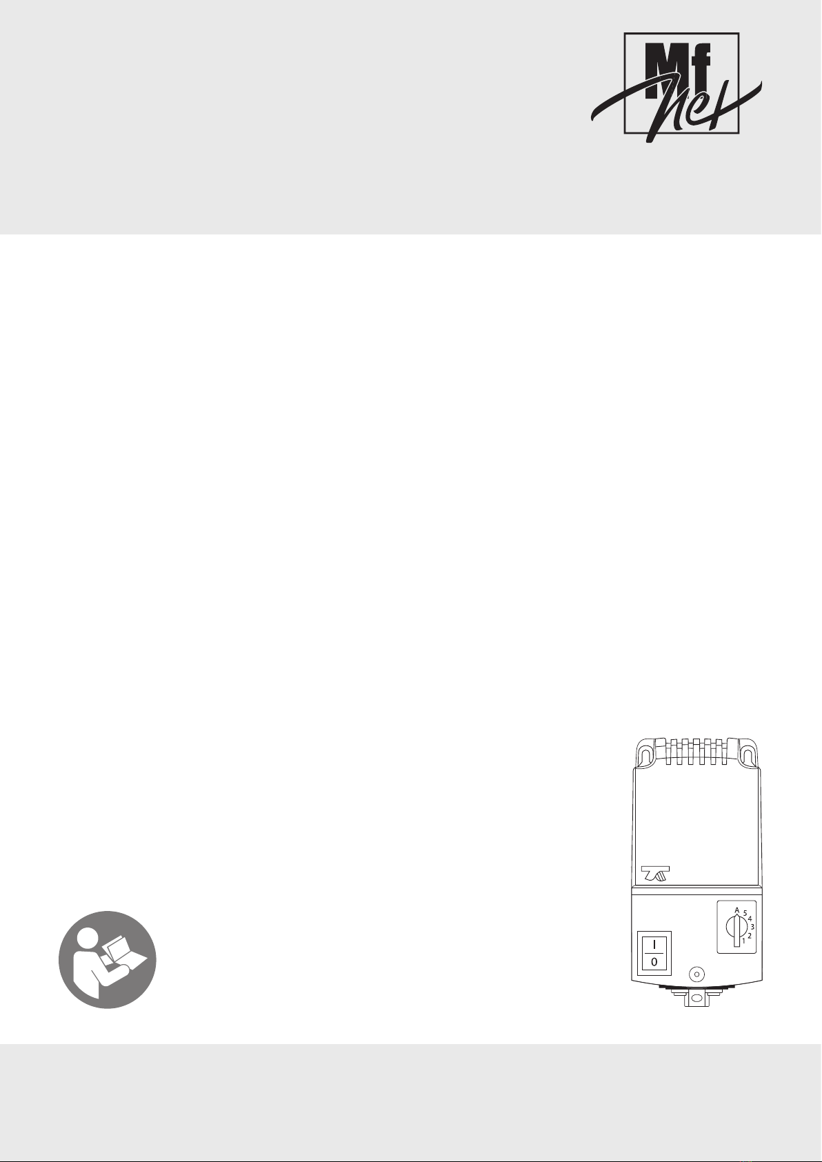
Vostermans Ventilation Mf-Net SEA-3N User manual

SEA-3N / SEA-6N
SEA-3N / SEA-6N
SEA-3N / SEA-6N
SEA-3N / SEA-6N
ENGLISH
Installation Instructions - Operating Instructions
NEDERLANDS
Installatie Instructies - Gebruiksaanwijzing
DEUTSCH
Installationsanleitung - Betriebsanleitung
FRANÇAIS
Instructions d'installation - Mode d'emploi
Document ID: INS00066-A
IMPORTANT - READ CAREFULLY BEFORE USE
BELANGRIJK - VOOR GEBRUIK ZORGVULDIG LEZEN
WICHTIG - VOR GEBRAUCH SORGFÄLTIG LESEN
IMPORTANT - LIRE ATTENTIVEMENT AVANT UTILISATION

SEA-3N / SEA-6N
2 | ENGLISH Original instructions INS00066-A
Table of Contents
1 Introduction ...........................................................................................2
2 Safety...................................................................................................... 2
3 Information.............................................................................................3
3.1 Overview .......................................................................................3
3.2 Intended use..................................................................................3
3.3 Technical Information....................................................................3
4 Installation .............................................................................................3
4.1 Mechanical ....................................................................................3
4.2 Electrical........................................................................................4
4.3 Wiring diagrams ............................................................................4
4.3.1 Manual control only ........................................................4
4.3.2 T15-WD fixed high and low step.....................................4
4.3.3 T15-WD fixed low and selectable high step ...................5
4.3.4 T15-2 ..............................................................................5
4.3.5 T15-4 | ETD-S | Relink-2S..............................................5
4.3.6 ETD-SN ..........................................................................6
5 Maintenance...........................................................................................6
6 Troubleshooting....................................................................................6
7 End of life...............................................................................................7
8 EU Declaration of Conformity ..............................................................7
Glossary.................................................................................................9
1 Introduction
NOTICE
This product is for professional use only.
Thank you for choosing this SEA-3N / SEA-6N.
IMPORTANT: READ THESE INSTRUCTIONS CAREFULLY BEFORE USE
KEEP THESE INSTRUCTIONS FOR FUTURE REFERENCE
These instructions are a part of this product and must be passed on to any
subsequent owner and/or user.
Contact your supplier if there are parts of these instructions that you do not
understand. Compliance with these instructions will ensure a safe and correct
use of this product.
Legal notice / Disclaimer
The scope of delivery may vary from product images shown. This document
was created with all due care. The information, instructions and parts listed
are current on the date this document was issued.
Improper use
No liability is accepted for damages resulting from improper use.
Packaging
If packaging materials are no longer required, dispose of them in accordance
with regulations that apply in your area.
Manufacturer:
This product is manufactured for Vostermans Ventilation B.V. by:
es-electronic UG
Brandenburger Straße 7
D-89287 Bellenberg
Germany
es-electronic UG is legally the manufacturer.
2 Safety
Safety messages
Your safety and the safety of others are very important. Important safety
messages are provided in these instructions.
READ THESE MESSAGES CAREFULLY
A safety message alerts you to potential hazards that could hurt you or
others. Each safety message is preceded by a safety symbol and one of four
signal words: DANGER, WARNING, CAUTION or NOTICE.
Explanation of the signal words used in this document
DANGER : You will be killed or seriously hurt if you do not follow instructions.
WARNING : You can be killed or seriously hurt if you do not follow
instructions.
CAUTION : You can be hurt if you do not follow instructions.
NOTICE : Is used to address practices not related to physical injury.
Explanation of the safety symbols used
General warning symbol
Warning for electricity
Warning for hot surfaces
Warning for sharp elements
Warning for automatic activation
Warning for strong magnetic fields
Warning for explosive materials
General mandatory action sign
Remark: not all of the listed symbols may be used in this document

SEA-3N / SEA-6N
INS00066-A Original instructions ENGLISH | 3
3 Information
3.1 Overview
A
B
Illustration1:
1 ON-OFF switch
2 Step selection switch
A 105mm
B 220mm
3.2 Intended use
The SEA-3N and SEA-6N are transformer voltage controllers. They are
intended for providing speed control of single phase fans in 5 steps, by
changing the supply voltage to the fan motor.
The selection of the output voltages can be done:
• manually with the step selection switch without connecting a thermostat
or control module. Use switch position 1, 2, 3, 4 or 5.
• semi-automatic by using a T15-WD or T15-2 thermostat. Use switch po-
sition A.
• automatic by using a T15-4, ETD-S, ETD-SN thermostat or Relink-2S
module. Use switch position A.
Type Description
T15-WD Single mechanical thermostat
T15-2 Double mechanical thermostat (two single mechanical thermo-
stats in one housing)
T15-4 5 step mechanical thermostat. The thermostat switches from the
set temperature in steps of 1°C.
ETD-S
ETD-SN
Digital Electronic Step Thermostat
Relink-2S Electronic Step Control module (0-10V analogue input)
Table1: Description of available thermostat types
Thermostats and modules are optionally available. Contact your supplier for
more information.
Refer to the thermostats and modules documentation for detailed explanation
on the functioning of the thermostats and modules.
DANGER
If the transformer is controlled by a thermostat, the connected
fan can start automatically.
Risk of injury due to unexpected start.
DANGER
Do not use this product in explosive or potentially ex-
plosive atmospheres .
3.3 Technical Information
SEA-3N SEA-6N
Supply 1~ 230V±10%
50/60Hz
1~ 230V±10%
50/60Hz
Control capacity max 3A max 6A
Output
voltage
(% of sup-
ply voltage)
Step 1 35% 35%
Step 2 45% 45%
Step 3 50% 50%
Step 4 75% 75%
Step 5 100% 100%
Ambient operating temper-
ature range
0°C to 40°C 0°C to 40°C
Degree of Ingress Protec-
tion
IP54 IP54
Weight
Including packaging
3,7 kg
4,0 kg
5,2 kg
5,5 kg
Height x width x depth 240mm x 120mm x
130mm
240mm x 120mm x
130mm
4 Installation
►Before commencing installation
1. Check the product after you have received it and make sure it has not
been damaged during transport.
2. Check all the information on the rating plate and verify that this product
is suitable for the intended application.
3. Verify that the fan you wish to speed control with this transformer, is suit-
able for transformer speed control.
4.1 Mechanical
NOTICE
This product must be installed on a non-flammable surface
NOTICE
This product must be installed vertically with the cable entry
openings pointing downwards

SEA-3N / SEA-6N
4 | ENGLISH Original instructions INS00066-A
Illustration2: Vertical installation only
4.2 Electrical
NOTICE
Electrical connection must be carried out by a qualified electri-
cian. Electrical connections must be made in accordance with
local regulations.
Check the rating plate and verify that this product is suitable for the available
power supply.
More than one fan can be connected to the SEA-3N / SEA-6N as long as the
total current draw of all connected fans does not exceed the maximum current
load of the SEA-3N / SEA-6N.
Use the cable grommets and the clamps for the cable strain relief that are
supplied with the controller.
NOTICE
The transformer is thermally protected
Thermal protection is of the thermostat type TB: thermostat opening on
increase of temperature. The thermostat is self-resetting.
DANGER
If the built-in thermal protection of the transformer is activated,
the fan automatically restarts after cooling down.
Risk of injury due to unexpected start.
WARNING
The ON-OFF switch does not isolate this product from the
power supply
Grounding
The product must be connected to protective earth (PE).
4.3 Wiring diagrams
4.3.1 Manual control only
1 P2345
NL
L1 PEN PENU1
M
SEA-3N / SEA-6N
Illustration3: Manual step control only
• Manual control in 5 steps.
•NOTICE! Step selection switch position “A”: fan is off.
4.3.2 T15-WD fixed high and low step
1 P2345
M
NL
L1 PEN PENU1
SEA-3N / SEA-6N
T15-WD
12 P
Illustration4: T15-WD fixed high and low step
• With the step selection switch in position ”A”, the T15-WD will switch
between a high and low step.
• The high and low steps are both fixed and are selected during installa-
tion (dotted lines in wiring diagram).
• Manual step control is possible with the step selection switch.
NOTICE! It is recommended to install interference
suppression capacitors over the thermostat terminals. Class
X capacitor 0.47µF/250V. These capacitors are optionally
available, please contact your supplier for more
information.

SEA-3N / SEA-6N
INS00066-A Original instructions ENGLISH | 5
4.3.3 T15-WD fixed low and selectable high step
1 P2345
12 P
M
NL
L1 PEN PENU1
SEA-3N / SEA-6N
T15-WD
Illustration5: T15-WD fixed low and selectable high step
• The T15-WD will switch between a fixed low step (selected during install-
ation) and a selectable high step.
• The low step is fixed and is selected during installation (dotted lines in
wiring diagram). The high step is selected using the step selection
switch.
•NOTICE! In the high step: step selection switch position “A”: fan is
off.
NOTICE! It is recommended to install interference
suppression capacitors over the thermostat terminals. Class
X capacitor 0.47µF/250V. These capacitors are optionally
available, please contact your supplier for more
information.
4.3.4 T15-2
1 P2345
12 P 12 P
M
NL
L1 PEN PENU1
SEA-3N / SEA-6N
T15-2
min
max
Illustration6: T15-2
• The T15-2 will switch between a fixed low step, selectable intermediate
step, and the maximum step 5.
• The low step is fixed and is selected during installation (dotted lines in
wiring diagram).
• The intermediate step is selected using the step selection switch.
• The maximum step is fixed and is selected during installation.
•NOTICE! In the intermediate step and the maximum step: step se-
lection switch position “A”: fan is off.
NOTICE! It is recommended to install interference
suppression capacitors over the thermostat terminals. Class
X capacitor 0.47µF/250V. These capacitors are optionally
available, please contact your supplier for more
information.
4.3.5 T15-4 | ETD-S | Relink-2S
1 P2345
45 3 12 P
M
NL
L1 PEN PENU1
SEA-3N / SEA-6N
T15-4 / ETD-S / RELINK-2S
Illustration7: T15-4 | ETD-S | Relink-2S

SEA-3N / SEA-6N
6 | ENGLISH Original instructions INS00066-A
• With the step selection switch in position “A”, the T15-4, ETD-S or Re-
link-2S will switch between all 5 steps.
• Manual step control using the step selection switch is possible.
4.3.6 ETD-SN
1 P2345
32 41B 65 7
M
NL
L1 PEN PENU1
SEA-3N / SEA-6N
ETD-SN
Illustration8: ETD-SN
• With the step selection switch in position “A”, the ETD-SN will switch
between all 5 steps.
• Manual step control using the step selection switch is possible.
• See the manual of the ETD-SN how to select 5 steps.
5 Maintenance
►Maintenance tasks – TO BE CARRIED OUT EVERY 3 MONTHS
1. Check the controller for defects and remove any dirt that has accumu-
lated.
Cleaning
Clean the controller preferably using a soft brush.
6 Troubleshooting
WARNING
Troubleshooting and repairs must be performed by skilled per-
sons only!
DANGER
If the built-in thermal protection of the transformer is activated,
the fan automatically restarts after cooling down.
Risk of injury due to unexpected start.
DANGER
If the transformer is controlled by a thermostat, the connected
fan can start automatically.
Risk of injury due to unexpected start.
Fault Possible cause Possible remedy
No output voltage
Power supply is present. The ON-OFF switch is ON.
The pilot lamp on the switch is on.
Thermal protection has been activated.
Current draw is too high.
Reduce load.
Thermal protection has been activated.
Ambient temperature is too high.
Lower ambient temperature,
The specified ambient temperature range is
between 0°C and 40°C.
Thermostat or module is connected incorrectly Correct the wiring (see wiring diagrams).
No supply voltage
Power supply is not present. The ON-OFF switch is
ON. The pilot lamp on the switch is off.
A fuse has been switched off. Reset the fuse.
If the fuse switches off regularly, check the electrical
installation.
The wiring is incorrect or damaged. Correct and/or repair the wiring.
Output voltage present at the transformer.
The fan connected to the SEA-3N / SEA-6N trans-
former is not working correctly.
No voltage present at the fan.
A motor protection device has been activated.
Reset the motor protection device.
If the motor protection devices activates regularly,
check the electrical installation, or contact the manu-
facturer of the fan.
No voltage present at the fan.
The wiring is incorrect or damaged.
Correct and/or repair the wiring.
Voltage present at the fan.
The fan is defect or not working correctly.
Contact the manufacturer of the fan.
The SEA-3N / SEA-6N transformer does not re-
spond to the thermostat.
The wiring is incorrect or damaged. Correct and/or repair the wiring.
The thermostat is defect or not working correctly. Contact the manufacturer of the thermostat.

SEA-3N / SEA-6N
INS00066-A Original instructions ENGLISH | 7
7 End of life
Disposal
At the end of the life of this product, dispose of it properly in accordance with
regulations that apply in your area.
8 EU Declaration of Conformity

SEA-3N / SEA-6N
8 | ENGLISH Original instructions INS00066-A
EU Declaration of Conformity

SEA-3N / SEA-6N
INS00066-A Original instructions ENGLISH | 9
Glossary
Explosive atmosphere
A mixture of air, under atmospheric conditions, with flammable sub-
stances in the form of gases, vapours, mists or dusts in which, after igni-
tion has occurred, combustion spreads to the entire unburned mixture.

SEA-3N / SEA-6N
10 | NEDERLANDS Originele instructies INS00066-A
Inhoudsopgave
1 Introductie............................................................................................10
2 Veiligheid .............................................................................................10
3 Informatie.............................................................................................11
3.1 Overzicht .....................................................................................11
3.2 Bedoeld gebruik ..........................................................................11
3.3 Technische informatie .................................................................11
4 Installatie..............................................................................................11
4.1 Mechanisch .................................................................................11
4.2 Elektrisch.....................................................................................12
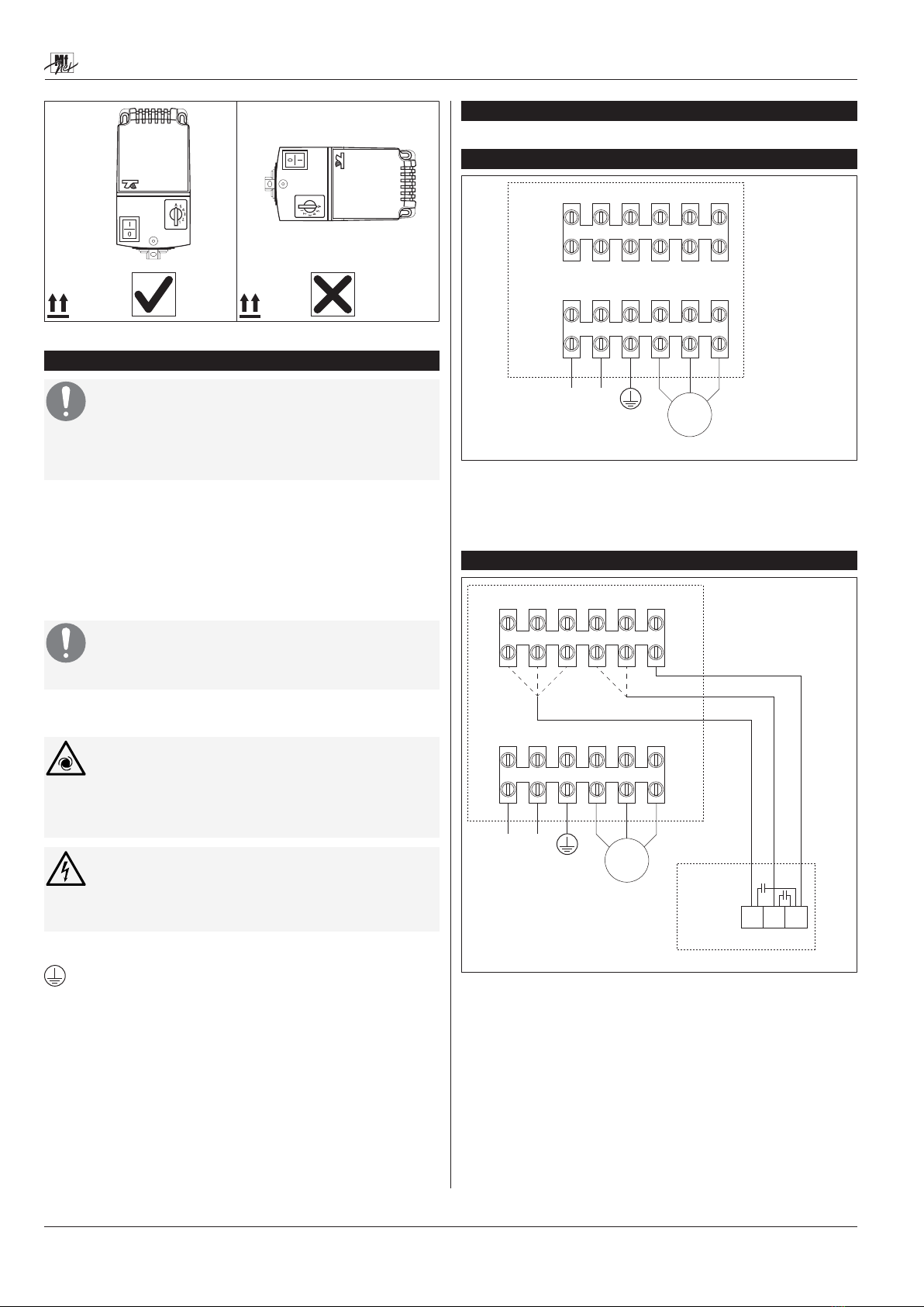
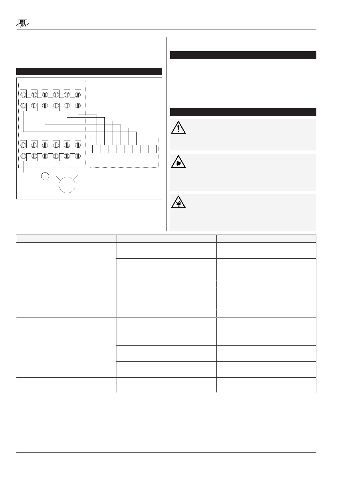
4.3 Aansluitschema’s ........................................................................12
4.3.1 Handmatige bediening..................................................12
4.3.2 T15-WD vaste hoge en lage stap.................................12
4.3.3 T15-WD vaste lage en selecteerbare hoge stap ..........13
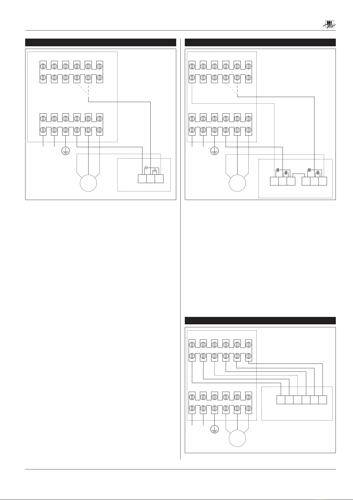
4.3.4 T15-2 ............................................................................13
4.3.5 T15-4 | ETD-S | Relink-2S............................................14
4.3.6 ETD-SN ........................................................................14
5 Onderhoud...........................................................................................14
6 Foutopsporing.....................................................................................14
7 Einde van de levensduur....................................................................16
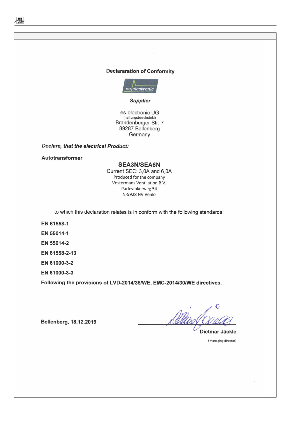
8 EU Verklaring van Overeenstemming ...............................................16
Begrippenlijst ......................................................................................18
1 Introductie
LET OP
Dit product is uitsluitend bestemd voor professioneel gebruik.
Bedankt dat u voor deze SEA-3N / SEA-6N heeft gekozen.
BELANGRIJK: LEES DEZE INSTRUCTIES ZORGVULDIG VOOR
GEBRUIK
BEWAAR DEZE INSTRUCTIES VOOR TOEKOMSTIG GEBRUIK
Deze instructies maken deel uit van dit product en moeten worden
doorgegeven aan iedere volgende eigenaar en/of gebruiker.
Neem contact op met uw leverancier als er delen van deze instructies zijn die
u niet begrijpt. Naleving van deze instructies garandeert een veilig en correct
gebruik van dit product.
Wettelijke kennisgeving / Afwijzing van aansprakelijkheid
De leveringsomvang kan afwijken van getoonde productafbeeldingen. Dit
document is met de grootst mogelijke zorgvuldigheid opgesteld. De
opgesomde informatie, instructies en onderdelen zijn actueel op de datum
van uitgifte van dit document.
Oneigenlijk gebruik
Voor schade die het gevolg is van oneigenlijk gebruik wordt geen
aansprakelijkheid aanvaard.
Verpakking
Als het verpakkingsmateriaal niet langer benodigd is, voer het dan af in
overeenstemming met plaatselijk geldende voorschriften.
Fabrikant:
Dit product wordt geproduceerd voor Vostermans Ventilation B.V. door:
es-electronic UG
Brandenburger Straße 7
D-89287 Bellenberg
Duitsland
es-electronic UG is wettelijk de fabrikant.
2 Veiligheid
Veiligheidsmededelingen
Uw veiligheid en de veiligheid van anderen is erg belangrijk. Belangrijke
veiligheidsmededelingen worden in deze instructies gegeven.
LEES DEZE MEDEDELINGEN ZORGVULDIG
Een veiligheidsmededeling waarschuwt u voor potentiële gevaren die u of
anderen kunnen kwetsen. Elke veiligheidsmededeling wordt voorafgegaan
door een veiligheidssymbool en één van de vier signaalwoorden: GEVAAR,
WAARSCHUWING, VOORZICHTIG of LET OP.
Uitleg van de signaalwoorden gebruikt in deze instructies
GEVAAR : U loopt dodelijk of ernstig letsel op als u instructies niet opvolgt.
WAARSCHUWING : U loopt mogelijk dodelijk of ernstig letsel op als u
instructies niet opvolgt.
VOORZICHTIG : U kunt letsel oplopen als u instructies niet opvolgt.
LET OP : Wordt gebruikt voor mededelingen die niet gerelateerd zijn aan het
oplopen van letsel.
Uitleg van de gebruikte veiligheidssymbolen
Algemeen waarschuwingssymbool
Waarschuwing voor elektriciteit
Waarschuwing voor hete oppervlakken
Waarschuwing voor scherpe delen
Waarschuwing voor automatisch inschakelen
Waarschuwing voor sterke magnetische velden
Waarschuwing voor explosieve materialen
Algemeen verplicht uit te voeren actie
Opmerking: mogelijk worden niet alle vermelde symbolen in deze instructies
gebruikt.

SEA-3N / SEA-6N
INS00066-A Originele instructies NEDERLANDS | 11
3 Informatie
3.1 Overzicht
A
B
Afbeelding1:
1 AAN-UIT schakelaar
2 Stappenschakelaar
A 105mm
B 220mm
3.2 Bedoeld gebruik
De SEA-3N en SEA-6N zijn transformator spanningsregelaars. Ze zijn
bedoeld om het toerental van 1-fase ventilatoren in 5 stappen te regelen door
de voedingsspanning van de ventilator motor te wijzigen.
De selectie van de uitgangsspanningen kan worden gedaan:
• handmatig, met de stappenschakelaar zonder aansluiting van een ther-
mostaat of bedieningsmodule. Gebruik positie 1, 2, 3,4 of 5 van de stap-
penschakelaar.
• halfautomatisch, gebruik makend van een T15-WD of T15-2 thermo-
staat. Gebruik positie A van de stappenschakelaar.
• automatisch, gebruik makend van een T15-4, ETD-S, ETD-SN thermo-
staat of Relink-2S module. Gebruik positie A van de stappenschakelaar.
Type Beschrijving
T15-WD Enkele mechanische thermostaat
T15-2 Dubbele mechanische thermostaat (twee enkele mechanische
thermostaten in één behuizing)
T15-4 5 staps mechanische thermostaat. De thermostaat schakelt in
stappen van 1°C vanaf de ingestelde temperatuur.
ETD-S
ETD-SN
Digitale elektronische stappen thermostaat
Relink-2S Elektronische stappen module (0-10V analoge ingang)
Tabel1: Beschrijving van de beschikbare thermostaat typen
Thermostaten en modules zijn optioneel verkrijgbaar. Neem contact op met
uw leverancier voor meer informatie.
Zie de documentatie bij de thermostaten en modules voor gedetailleerde
uitleg over de werking van de thermostaten en modules.
GEVAAR
Als de transformator wordt geregeld door een thermostaat, kan
de aangesloten ventilator automatisch starten.
Gevaar voor letsel door onverwachte start.
GEVAAR
Gebruik dit product niet in explosieve of potentieel explosie-
ve atmosferen.
3.3 Technische informatie
SEA-3N SEA-6N
Voeding 1~ 230V±10%
50/60Hz
1~ 230V±10%
50/60Hz
Regelcapaciteit max 3A max 6A
Uitvoer-
spanning
(% Van de
voe-
dingsspan-
ning)
Stap 1 35% 35%
Stap 2 45% 45%
Stap 3 50% 50%
Stap 4 75% 75%
Stap 5 100% 100%
Omgevingstemperatuurbe-
reik
0°C tot 40°C 0°C tot 40°C
Beschermingsgraad IP54 IP54
Gewicht
Inclusief verpakking
3,7 kg
4,0 kg
5,2 kg
5,5 kg
Hoogte x breedte x diepte 240mm x 120mm x
130mm
240mm x 120mm x
130mm
4 Installatie
►Voor aanvang van installatie
1. Controleer het product na ontvangst en verzeker u ervan dat deze tij-
dens het transport niet beschadigd is.
2. Bekijk alle gegevens op de typeplaat en controleer of dit product ge-
schikt is voor de beoogde toepassing.
3. Controleer of de ventilator die u met deze transformator wilt regelen, ge-
schikt is voor transformatorregeling.
4.1 Mechanisch
LET OP
Dit product moet op een onbrandbaar oppervlak worden geïn-
stalleerd
LET OP
Dit product moet verticaal worden geïnstalleerd met de kabelin-
voeropeningen naar beneden

SEA-3N / SEA-6N
12 | NEDERLANDS Originele instructies INS00066-A
Afbeelding2: Alleen verticale installatie
4.2 Elektrisch
LET OP
De elektrische aansluiting moet worden uitgevoerd door een
gekwalificeerde elektricien. De elektrische aansluiting moet in
overeenstemming met de plaatselijke voorschriften worden uit-
gevoerd.
Controleer de typeplaat en controleer of dit product geschikt is voor de
aanwezige stroomvoorziening.
Meer dan één ventilator kan op de SEA-3N / SEA-6N worden aangesloten
zolang de totale stroomopname van alle aangesloten ventilatoren de
maximale stroombelasting van de SEA-3N / SEA-6N niet overschrijdt.
Gebruik de kabeltules en de klemmen voor de kabel trekontlasting die bij de
regelaar zijn meegeleverd.
LET OP
De transformator is thermisch beveiligd
Thermische beveiliging is het type thermostaat TB: thermostaat opent bij
temperatuurstijging. De thermostaat reset zichzelf.
GEVAAR
Als de ingebouwde thermische beveiliging van de transforma-
tor wordt geactiveerd, start de ventilator na het afkoelen auto-
matisch opnieuw.
Gevaar voor letsel door onverwachte start.
WAARSCHUWING
De AAN-UIT-schakelaar scheidt dit product niet van de stroom-
voorziening
Aarding
Het product moet worden aangesloten op veiligheidsaarde (PE).
4.3 Aansluitschema’s
4.3.1 Handmatige bediening
1 P2345
NL
L1 PEN PENU1
M
SEA-3N / SEA-6N
Afbeelding3: Alleen handmatige bediening
• Handmatige bediening in 5 stappen.
•LET OP!Stappenschakelaar positie “A”: ventilator is uit.
4.3.2 T15-WD vaste hoge en lage stap
1 P2345
M
NL
L1 PEN PENU1
SEA-3N / SEA-6N
T15-WD
12 P
Afbeelding4: T15-WD vaste hoge en lage stap
• Met de stappenschakelaar in positie "A" schakelt de T15-WD tussen een
hoge en lage stap.
• De hoge en lage stap zijn beide vast en worden tijdens de installatie ge-
selecteerd (stippellijnen in het aansluitschema).
• Handmatige bediening is mogelijk met de stappenschakelaar.
LET OP! Het wordt aanbevolen om
ontstoringscondensatoren over de thermostaatklemmen te
installeren. Klasse X condensator 0.47μF / 250V. Deze
condensatoren zijn optioneel verkrijgbaar, neem contact op
met uw leverancier voor meer informatie.

SEA-3N / SEA-6N
INS00066-A Originele instructies NEDERLANDS | 13
4.3.3 T15-WD vaste lage en selecteerbare hoge stap
1 P2345
12 P
M
NL
L1 PEN PENU1
SEA-3N / SEA-6N
T15-WD
Afbeelding5: T15-WD vaste lage en selecteerbare hoge stap
• De T15-WD schakelt tussen een vaste lage instap (geselecteerd tijdens
installatie) en een selecteerbare hoge stap.
• De lage stap is vast en wordt tijdens de installatie geselecteerd (stippel-
lijnen in het aansluitschema). De hoge stap wordt geselecteerd met de
stappenschakelaar.
•LET OP!In de hoge stap: stappenschakelaar positie “A”:
ventilator is uit.
LET OP! Het wordt aanbevolen om
ontstoringscondensatoren over de thermostaatklemmen te
installeren. Klasse X condensator 0.47μF / 250V. Deze
condensatoren zijn optioneel verkrijgbaar, neem contact op
met uw leverancier voor meer informatie.
4.3.4 T15-2
1 P2345
12 P 12 P
M
NL
L1 PEN PENU1
SEA-3N / SEA-6N
T15-2
min
max
Afbeelding6: T15-2
• De T15-2 schakelt tussen een vaste lage stap, selecteerbare tussenstap
en de maximale stap 5.
• De lage stap is vast en wordt tijdens de installatie geselecteerd (stippel-
lijnen in het aansluitschema).
• De tussenstap wordt geselecteerd met de stappenschakelaar.
• De maximale stap is vast en wordt geselecteerd tijdens de installatie.
•LET OP!In de tussenstap en de maximale stap: stappen-
schakelaar positie “A”: ventilator is uit.
LET OP! Het wordt aanbevolen om
ontstoringscondensatoren over de thermostaatklemmen te
installeren. Klasse X condensator 0.47μF / 250V. Deze
condensatoren zijn optioneel verkrijgbaar, neem contact op
met uw leverancier voor meer informatie.

SEA-3N / SEA-6N
14 | NEDERLANDS Originele instructies INS00066-A
4.3.5 T15-4 | ETD-S | Relink-2S
1 P2345
45 3 12 P
M
NL
L1 PEN PENU1
SEA-3N / SEA-6N
T15-4 / ETD-S / RELINK-2S
Afbeelding7: T15-4 | ETD-S | Relink-2S
• Met de stappenschakelaar in positie “A”, schakelt de T15-4, ETD-S of
Relink-2S tussen alle 5 stappen.
• Handmatige bediening is mogelijk met de stappenschakelaar.
4.3.6 ETD-SN
1 P2345
32 41B 65 7
M
NL
L1 PEN PENU1
SEA-3N / SEA-6N
ETD-SN
Afbeelding8: ETD-SN
• Met de stappenschakelaar in positie “A”, schakelt de ETD-SN tussen alle
5 stappen.
• Handmatige bediening is mogelijk met de stappenschakelaar.
• Zie de handleiding van de ETD-SN hoe 5 stappen te selecteren.
5 Onderhoud
►Onderhoudstaken - ELKE 3 MAANDEN UIT TE VOEREN
1. Controleer de regelaar op defecten en verwijder vuil dat zich afgezet
heeft.
Reiniging
Reinig de regelaar bij voorkeur met een zachte borstel.
6 Foutopsporing
WAARSCHUWING
Foutopsporingen en reparaties mogen alleen door vakmensen
worden uitgevoerd!
GEVAAR
Als de ingebouwde thermische beveiliging van de transforma-
tor wordt geactiveerd, start de ventilator na het afkoelen auto-
matisch opnieuw.
Gevaar voor letsel door onverwachte start.
GEVAAR
Als de transformator wordt geregeld door een thermostaat, kan
de aangesloten ventilator automatisch starten.
Gevaar voor letsel door onverwachte start.
Fout Mogelijke oorzaak Mogelijke oplossing
Geen uitgangsspanning.
Stroomvoorziening is aanwezig. De AAN-UIT scha-
kelaar staat op AAN. Het controlelampje op de
schakelaar brandt.
Thermische beveiliging is geactiveerd.
Stroomopname te hoog.
Belasting verminderen.
Thermische beveiliging is geactiveerd.
Omgevingstemperatuur te hoog.
Omgevingstemperatuur verlagen.
Het gespecificeerde bereik van de omgevingstem-
peratuur ligt tussen 0°C en 40°C.
Thermostaat of module verkeerd aangesloten. Corrigeer de aansluiting (zie aansluitschema's).
Geen ingangsspanning.
Stroomvoorziening is niet aanwezig. De AAN-UIT
schakelaar staat op AAN. Het controlelampje op de
schakelaar brandt niet.
Een zekering is uitgeschakeld. Reset de zekering.
Als de zekering regelmatig wordt uitgeschakeld,
controleer de elektrische installatie.
De bekabeling is niet correct of beschadigd. Corrigeer of repareer de bekabeling.
Er is uitgangsspanning op de transformator. Geen spanning op de ventilator. Reset de motorbeveiligingsschakelaar.

SEA-3N / SEA-6N
INS00066-A Originele instructies NEDERLANDS | 15
Fout Mogelijke oorzaak Mogelijke oplossing
De ventilator die aangesloten is op de SEA-3N /
SEA-6N werkt niet correct.
Een motorbeveiligingsschakelaar is geactiveerd. Als de motorbeveiligingsschakelaar regelmatig
wordt uitgeschakeld, controleer de elektrische instal-
latie, of neem contact op met de fabrikant van de
ventilator.
Geen spanning op de ventilator.
De bekabeling is niet correct of beschadigd.
Corrigeer of repareer de bekabeling.
Er is spanning op de ventilator.
De ventilator is defect of werkt niet correct.
Neem contact op met de fabrikant van de ventilator.
De SEA-3N / SEA-6N transformator reageert niet op
de thermostaat.
De bekabeling is niet correct of beschadigd. Corrigeer of repareer de bekabeling.
De thermostaat is defect of werkt niet correct. Neem contact op met de fabrikant van de thermo-
staat.

SEA-3N / SEA-6N
16 | NEDERLANDS Originele instructies INS00066-A
7 Einde van de levensduur
Verwijdering
Aan het einde van de levensduur van dit product, voer het product af in
overeenstemming met de voorschriften die van toepassing zijn in uw regio.
8 EU Verklaring van Overeenstemming

SEA-3N / SEA-6N
INS00066-A Originele instructies NEDERLANDS | 17
EU Verklaring van Overeenstemming

SEA-3N / SEA-6N
18 | NEDERLANDS Originele instructies INS00066-A
Begrippenlijst
Explosieve atmosfeer
Een mengsel van lucht, onder atmosferische omstandigheden, met
brandbare stoffen in de vorm van gassen, dampen, nevels of stof, waar-
in de verbranding zich na ontsteking uitbreidt tot het gehele onverbrande
mengsel.

SEA-3N / SEA-6N
INS00066-A DEUTSCH | 19
Inhaltsverzeichnis
1 Einleitung.............................................................................................19
2 Sicherheit.............................................................................................19
3 Informationen ......................................................................................20
3.1 Übersicht .....................................................................................20
3.2 Zweckmäßiger Gebrauch............................................................20
3.3 Technische Daten .......................................................................20
4 Installation ...........................................................................................20
4.1 Mechanik.....................................................................................20
4.2 Elektrik.........................................................................................21
4.3 Schaltdiagramme ........................................................................21
4.3.1 Nur manuelle Steuerung...............................................21
4.3.2 T15-WD feste hohe und niedrige Stufe ........................21
4.3.3 T15-WD feste niedrige Stufe und variable hohe Stufe
......................................................................................22
4.3.4 T15-2 ............................................................................22
4.3.5 T15-4 | ETD-S | Relink-2S............................................22
4.3.6 ETD-SN ........................................................................23
5 Wartung................................................................................................23
6 Störbehebung......................................................................................23
7 Ende der Lebensdauer........................................................................24
8 EU-Konformitätserklärung .................................................................24
Glossar.................................................................................................26
1 Einleitung
HINWEIS
Dieses Produkt ist nur für den professionellen Gebrauch vorge-
sehen.
Vielen Dank für den Kauf des SEA-3N / SEA-6N.
WICHTIG: LESEN SIE DIESE BETRIEBSANLEITUNG VOR DEM
GEBRAUCH SORGFÄLTIG DURCH
BEWAHREN SIE DIE BETRIEBSANLEITUNG FÜR EIN ZUKÜNFTIGES
NACHSCHLAGEN GUT AUF
Diese Betriebsanleitung ist Bestandteil des Produkts und muss an zukünftige
Besitzer und/oder Benutzer weitergegeben werden.
Wenden Sie sich an Ihren Händler, falls Sie Teile dieser Betriebsanleitung
nicht verstehen. Durch die Einhaltung der Betriebsanleitung wird der
ordnungsgemäße Gebrauch dieses Produkts gewährleistet.
Impressum / Disclaimer
Der Lieferumfang kann von den gezeigten Produktabbildungen abweichen.
Dieses Dokument wurde mit größter Sorgfalt erstellt. Die aufgeführten
Informationen, Anweisungen und Teile sind zum Zeitpunkt der Erstellung
dieses Dokuments aktuell.
Fehlerhafte Verwendung
Für Schäden, die durch unsachgemäßen Gebrauch entstehen, wird keine
Haftung übernommen.
Verpackung
Wenn die Verpackungsmaterialien nicht mehr benötigt werden, entsorgen Sie
sie nach den in Ihrer Nähe geltenden Vorschriften.
Hersteller:
Die Herstellung dieses Produkts erfolgte für Vostermans Ventilation B.V.
durch:
es-electronic UG
Brandenburger Straße 7
D-89287 Bellenberg
Deutschland
es-electronic UG gilt rechtlich als Hersteller dieses Produkts.
2 Sicherheit
Sicherheitshinweise
Ihre Sicherheit und die Sicherheit anderer sind sehr wichtig. Wichtige
Sicherheitshinweise sind in dieser Anleitung zur Verfügung gestellt.
LESEN SIE DIESE HINWEISE SORGFÄLTIG
Ein Sicherheitshinweis warnt vor möglichen Gefahren, die Sie oder andere
verletzen könnten. Jeder Sicherheitshinweis wird von einem
Sicherheitssymbol und einer von vier Signalworten vorangegangen:
GEFAHR, WARNUNG, VORSICHT oder HINWEIS.
Erläuterung der in diesem Dokument verwendeten Signalwörter
GEFAHR: Wenn Sie die Anweisungen nicht befolgen, werden Sie getötet
oder schwer verletzt.
WARNUNG: Sie können getötet oder schwer verletzt werden, wenn Sie den
Anweisungen nicht folgen.
VORSICHT: Sie können verletzt werden, wenn Sie Anweisungen nicht folgen.
HINWEIS: Wird verwendet, um Praktiken zu geben, die nicht mit
Körperverletzungen zusammenhängen.
Erklärung der verwendeten Sicherheitssymbole
Allgemeines Warnsymbol
Warnung für Strom
Warnung für heiße Oberflächen
Warnung für sharfe Elemente
Warnung für automatische Aktivierung
Warnung für starke Magnetfelder
Warnung für Explosivstoffe
Allgemeines Gebotszeichen
Anmerkung: nicht alle aufgeführten Symbole können in diesem Dokument
verwendet werden

SEA-3N / SEA-6N
20 | DEUTSCH INS00066-A
3 Informationen
3.1 Übersicht
A
B
Abb.1:
1 EIN/AUS-Schalter
2 Stufenschalter
A 105mm
B 220mm
3.2 Zweckmäßiger Gebrauch
Der SEA-3N und der SEA-6N sind Traforegler. Sie sind dafür vorgesehen, die
Drehzahl von einphasige Ventilatoren in 5-Stufen zu regeln, indem sie die
Versorgungsspannung des Ventilator-Motors verändern.
Die Ausgangsspannung kann wie folgt eingestellt werden:
• manuell mit dem Stufenschalter ohne Anschluss eines Thermostats oder
Steuermoduls. Verwenden Sie die Schalterpositionen 1, 2, 3, 4 oder 5.
• halbautomatisch unter Verwendung eines T15-WD oder T15-2 Thermo-
stats. Verwenden Sie die Schalterposition A.
• automatisch unter Verwendung eines T15-4, ETD-S oder ETD-SN Ther-
mostats oder eines Relink-2S Moduls. Verwenden Sie die Schalterpositi-
on A.
Typ Erläuterung
T15-WD Einzelnes mechanisches Thermostat
T15-2 Doppeltes mechanisches Thermostat (zwei einzelne Thermo-
state in einem Gehäuse)
T15-4 5-stufiges mechanisches Thermostat. Das Thermostat ändert
die eingestellte Temperatur in Schritten von 1°C.
ETD-S
ETD-SN
Digitales elektronisches Mehrstufen-Thermostat
Relink-2S Elektronisches Mehrstufen-Steuermodul (0-10V analoger Ein-
gang)
Tab.1: Erläuterung verfügbarer Thermostat-Typen
Thermostate und Module sind optional erhältlich. Lassen Sie sich von Ihrem
Händler entsprechend beraten.
In den Unterlagen der Thermostate und Module finden Sie detaillierte
Beschreibungen zu deren jeweiligen Funktionen.
GEFAHR
Falls der Transformator von einem Thermostat gesteuert wird,
startet der verbundene Ventilator automatisch.
Es besteht Verletzungsgefahr durch versehentliches Anlaufen des
Geräts.
GEFAHR
Verwenden Sie das Produkt nicht in explosiven oder po-
tentiell explosiven Umgebungen .
3.3 Technische Daten
SEA-3N SEA-6N
Versorgungsspannung 1~ 230V±10%
50/60Hz
1~ 230V±10%
50/60Hz
Regelleistung max. 3A max. 6A
Ausgangs-
spannung
(% der Ver-
sorgungs-
spannung)
Stufe 1 35% 35%
Stufe 2 45% 45%
Stufe 3 50% 50%
Stufe 4 75% 75%
Stufe 5 100% 100%
Umgebungstemperatur 0°C bis 40°C 0°C bis 40°C
Schutzgrad IP54 IP54
Gewicht
Einschließlich Verpackung
3,7 kg
4,0 kg
5,2 kg
5,5 kg
Höhe x Breite x Tiefe 240mm x 120mm x
130mm
240mm x 120mm x
130mm
4 Installation
►Vor der Installation
1. Überprüfen Sie das Produkt nach der Lieferung auf mögliche Transport-
schäden.
2. Überprüfen Sie alle Angaben auf dem Typenschild und vergewissern Sie
sich, dass dieses Produkt für den vorgesehenen Einsatz geeignet ist.
3. Vergewissern Sie sich, dass der Ventilator, dessen Drehzahl Sie mit die-
sem Transformator steuern möchten, für die Steuerung durch einen
Transformator geeignet ist.
4.1 Mechanik
HINWEIS
Dieses Produkt muss auf einer nicht brennbaren Oberfläche
montiert werden
HINWEIS
Dieses Produkt muss vertikal und mit den Kabelverschraubun-
gen nach unten gerichtet installiert werden
This manual suits for next models
1
Table of contents
Languages:
Popular Thermostat manuals by other brands

Travis Industries
Travis Industries 99300650 quick start guide

OJ Electronics
OJ Electronics OCC4 instructions

Paul
Paul Universal Thermostat operating instructions

Vive
Vive TP-N-721 installation manual

Neptronic
Neptronic TRO24T4XYZ3 Specification & installation instructions

Eaton
Eaton chvz-01/03 operating instructions