Votronic Battery Protector 40 User manual

Installation and Operating Manual
Battery Protector 40 Switching Capacity 12 V / 40 A No. 3075
Battery Protector 40 Motor Switching Capacity 12 V / 40 A No. 3073
Battery Protector 40/24 Switching Capacity 24 V / 40 A No. 6075
Battery Protector 40/24 Motor Switching Capacity 24 V / 40 A No. 6073
Please read the mounting instructions and operating manual completely prior to starting
connection and start-up.
The VOTRONIC Battery Protector 40 had been designed for campers, boats and intervention vehicles and is inserted
between battery and consumers. It protects the battery from dangerous total discharge and the consumers from low
voltage and overvoltage.
The reset to normal operation is effected automatically, as soon as there is an increase of the voltage to 12.5 V due to
battery recovery or short-time charging. Manual cancelling of the disconnection is also possible by means of the function
“EMERGENCY ON”.
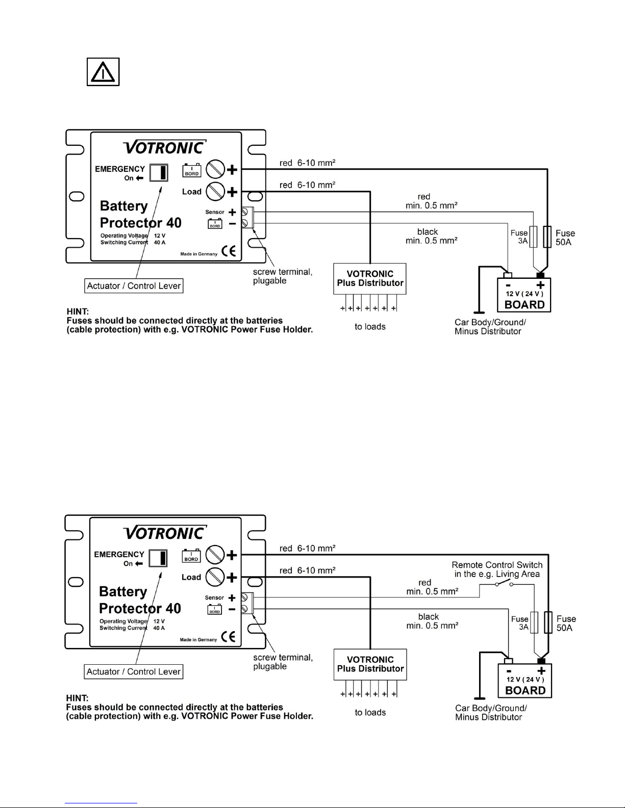
Remote control of the Battery Protector 40 is possible by means of the terminal "Sensor +" and a simple switch (single-
pole ON / OFF). By this, it is becoming an efficient battery main switch.
Also the EMERGENCY-ON function can be remote-controlled.
The range of application extends to mission vehicles, campers, boats and solar systems:
Suitable for any type and brand of lead storage battery (Acid, Gel, Dryfit, Heavy Duty, Solar, Fleece, AGM etc.)
The unit protects the battery from dangerous total discharge.
It protects the consumers and the equipment from low voltage as well as overvoltage in case of failures.
Automatic restart after battery recovery (charging).
High switching current 40 A, short-time overload of 60 A is admissible.
It can also be used as battery main switch by means of a simple ON / OFF switch (remote control, e. g. from the
living area).
EMERGENCY-ON function for low battery voltage.
Display of the switching state being visible from outside.
Compensation of the voltage loss in the battery cable by separate sensor cable.
The electronic delay avoids premature reaction, such as in case of voltage drop or if powerful consumers have
been connected.
Suitable for continuous operation (extremely low own consumption 0.002 A (in conformity with EN13796).
No own electricity consumption in case of disconnection by means of external switch (remote control).
Installation:
1. Chose an installation place being clean and being protected from humidity and dust.
2. The installation place of the unit should be chosen in such way, that the cables of battery and consumers can be as
short as possible (losses). Ensure, that the control lever „EMERGENCY“ can always be operated and that it is not
blocked by soiling, objects, transported goods etc.
3. The unit is fastened solidly with screws in the casing flanges. The unit can be installed in any position. However,
ensure that the terminals and operating elements are easily accessible.
4. Observe to fasten the connection cables in such a way, that neither tensible force, nor force of pressure or bending
load are existing.
Connection (Please Observe Connection Plan 1 or 2):
ALWAYS DISCONNECT THE POWER SUPPLY TO THE BATTERY PRIOR TO WORKING ON THE
ELECTRIC SYSTEM TO AVOID SHORT-CIRCUITS!
It is recommendable to use connection cables of different colours to avoid defects and malfunctions due to mixed up
connections.
Basically: Only use red cables for Plus connection "+" and black cables for minus connection "-".
Eventual wrong polarization will result in failure of the unit, but it will not be damaged.
If the connection cables for battery and „Load“ are mixed up, the unit will continue working, but the low-voltage
disconnection will not be functioning. The battery continues supplying the consumers.
Observe the cable cross-sections and the polarity. Insert the fuses near the battery (protection against cable fire).

-2-
Start-up:
If the control lever is blocked (manual blocking, dirt, dust) the electronic system will fail! Now, there is the risk
of total discharge of the battery. On the other hand, the battery charge can be utilized completely in an
extreme case of emergency (positioning light, lighting etc.).
1. Application as pure protection against total discharge:
Disconnection: a.) Automatically in case of total discharge (low voltage) e. g. below 10.7 V after 10 seconds.
b.) Automatically in case of overvoltage e. g. above 15.5 V after 10 seconds.
c.) Manual disconnection is possible by means of the control lever (main switch function). In this
case, restart is also to be effected manually.
Restart: d.) Automatically after total discharge and battery recovery / battery charging e. g. over 12.5 V
e.) Automatically after overvoltage and decreasing voltage e. g.below 15 V
f.) Manually by actuation of the change lever „EMERGENCY“. If the battery voltage will again be
decreasing due to consumer load, the unit will be disconnected again! This procedure should not
be repeated unnecessarily often to maintain the longevity of the battery.
2. Additional application as main switch,
Remote control by means of switch ON / OFF in the living area:
This type of switching allows an effective remote control of the unit by means of a switch being located in the living area.
Since the load of the switch is very low (0.002 A), an execution as microswitch is sufficient.
If the switch is in position "OFF", the entire electronic system will be completely disconnected. The own electricity
consumption being anyhow very low is ceased.

-3-
Disconnection: a.) Automatically, as described below 1. a.) and b.).
b.) Manually, at any time by means of the switch in the living area "OFF", as described below c.).
Restart: c.) Automatically, when positioning the switch in the living area to "ON", as described below d.) and
e.).
d.) Manually, at any time by positioning the switch in the living area to "ON".
EMERGENCY-ON by means of the switch in the living area:
If the Battery Protector 40 has been switched-off duly due to a very low battery voltage, it can be restarted by means of the
remote control (emergency function). Set the switch in the living area to position "OFF" and restart after approx. 1 -2
seconds. This can be repeated several times, but the consumers being not necessarily required should be disconnected for
relief of the battery to avoid that the unit will be disconnected immediately after that.
If the Battery Protector 40 is disconnected by means of the switch in the living are (main switch function), it
can be reactivated nevertheless by means of the control lever "EMERGENCY". However, in this case, the
electronic monitoring system is not active. Therefore, there is the risk of total discharge of the battery. On the
other hand, the battery charge can be utilized completely in an extreme case of emergency (positioning
lights, lighting etc.).
Safety Regulations:
Appropriate Application:
The Battery Protector 40 has been designed according to the valid safety regulations.
Appropriate application is restricted to:
1. Deep discharge protection for lead batteries with the specified nominal voltage
2. Utilisation of the indicated fuses near the battery for protection of the cabling of the unit.
3. Technically faultless condition.
4. Installation in a well-ventilated room, protected from rain, humidity, dust, aggressive battery gas, as well
as in an environment being free from condensation water.
Never use the unit at locations where the risk of gas or dust explosion exists!
Open-air operation of the unit is not allowed.
Cables are always to be laid in such a way that damage is excluded. Observe to fasten them tightly.
Never lay 12 V (24 V) cables and 230 V mains supply cables into the same cable conduit (empty conduit).
Live cables or leads being connected to the unit are periodically to be checked for insulation faults, points of
break or loosened connections. If a fault has been detected, disconnect the unit immediately from all
connections and remedy the faults.
The unit is to be disconnected from any connection prior to execution of electrically welding or work on the
electric system.
If the non-commercial end-user is not able to recognize the characteristic values being valid for a unit or the
regulations to be observed, a specialist is always to be consulted.
The user/buyer is obliged to observe any construction and safety regulations.
The unit is not equipped with parts, which can be replaced by the user.
Keep children away from the batteries and the connections.
Observe the safety regulations of the battery manufacturer.
Ventilate the battery room.
Non-observance may result in injury or material damage.
The warranty period is 24 months from the purchase date (against presentation of the sales slip or invoice).
The warranty will be void in case of any inappropriate utilisation of the unit, if it is used beyond the technical
specification, in case of improper operation or external intervention. We do not assume any liability for any
damage resulting hereof. The liability exclusion is extended to any service being executed by third, which has
not been ordered by us in writing. Service is to be effected exclusively by VOTRONIC Lauterbach.
Operating Instructions:
Overvoltage Limitation:
If the voltage rate is e. g. 15.5 V, the supply voltage will be switched-off to protect sensitive consumers. Restart will be
effected 10 seconds after the voltage is below e. g. 15.0 V. If such high voltage levels are reached repeatedly, charging
controller, battery, charger and battery terminals should be checked.

-4-
Delivery Scope:
Battery Protector 40
Operating Manual
Battery Life:
Application of the Battery Protector 40 can prolong the battery life considerably. This is obtained by observation of the
following general rules:
In contrast to other battery types, batteries on lead basis do not have any harmful memory effect. Consequently: In case of
doubt, partially discharged batteries are to be charged fully as soon as possible.
Store only fully charged batteries and recharge them periodically, particularly in case of used (older) batteries and higher
temperatures. Sulphation of the battery plates due to total discharge is to be prevented by immediate charging, particularly
in case of low and high ambient temperatures.
Observe the instructions and technical leaflets of the battery manufacturers.
Keep batteries cool; choose an appropriate location for installation.
Technical Data: Battery Battery Battery Battery
Protector Protector Protector Protector
40 40 Motor 40/24 40/24 Motor
Nr. 3075 Nr. 3073 Nr. 6075 Nr. 6073
Nominal Operating Voltage (DC): 12 V 12 V 24 V 24 V
Operating Voltage Range DC: 8.5 V - 25 V 8.5 V - 25 V 17 V - 36 V 17 V - 36 V
Current Consumption ON 2 mA; 0.002 A 2 mA; 0.002 A 2 mA; 0.002 A 2 mA; 0.002 A
Current Consumption OFF 2 mA; 0,002 A 2 mA; 0,002 A 2 mA; 0,002 A 2 mA; 0,002 A
Current Consumption ON by Remote Control 2 mA; 0.002 A 2 mA; 0.002 A 2 mA; 0.002 A 2 mA; 0.002 A
Current Consumption OFF by Remote Control 0 mA 0 mA 0 mA 0 mA
Switching Current (Load) max.: 40 A continuous, 52 A short-time 10 sec., 60 A 1 sec.
Low-voltage Disconnection
Disconnection Point: 10.7 V 11.8 V 21.4 V 23.6 V
Cutoff Delay: 10 Sek. 10 Sek. 10 Sek. 10 Sek
Cut-in Point (Automatic Return): 12.5 V 12.8 V 25 V 25.6 V
Cut-in Delay: 2 Sec. 2 Sec. 2 Sec. 2 Sec.
Overvoltage Disconnection
Cutoff Point: 15.5 V 15.5 V 31 V 31 V
Cutoff Delay: 2 Sec. 2 Sec. 2 Sec. 2 Sec.
Overvoltage Return: 15.0 V 15.0 V 30 V 30 V
Cut-in Delay: 10 Sec. 10 Sec. 10 Sec. 10 Sec.
Battery Types: Suitable for any lead storage battery with nominal voltage 12 V / 24 V
Acid, Gel, Dryfit, Heavy Duty, Solar, Fleece, AGM etc.
Fitting Position of Unit: any any any any
Temperature Range Storage: -20/+50 °C -20/+50 °C -20/+50 °C -20/+50 °C
Protection Class: IP21 IP21 IP21 IP21
Dimensions (mm): 90 x 60 x 38 mm 90 x 60 x 38 mm 90 x 60 x 38 mm 90 x 60 x 38 mm
Weight: 97 g 97 g 97 g 97 g
Ambient Conditions, Humidity of Air: max. 95 % RH, No Condensation
Declaration of Conformity:
According to the stipulations of the regulations 2006/95/EG, 2004/108/EG, 95/54/EG this product corresponds to the
following standards or standardized documents:
EN55014; EN55022 B; DIN14685; EN61000-4-2; EN61000-4-3; EN61000-4-4
Disposal of the
product in the
normal household
waste is not
allowed.
The product
conforms to RoHS.
Thus, it complies
with the directives for Reduction of
Hazardous Substances in Electrical and
Electronic Equipment.
Subject to misprints, errors and technical modification without notice.
All rights reserved, particularly the right of reproduction. Copyright VOTRONIC 01/2018.
Made in Germany by VOTRONIC Electronic-Systeme GmbH & Co. KG, Johann-Friedrich-Diehm-Str. 10, D-36341 Lauterbach
Phone: +49 (0) 6641/91173-0 Fax: +49 (0) 6641/91173-20 E-mail: [email protected] Internet: www.votronic.de
This manual suits for next models
7
Table of contents
Popular Surge Protector manuals by other brands

Eaton
Eaton Crouse-hinds series instruction sheet

Vega
Vega B62-36G operating instructions

Europa components
Europa components ECSS-102 Technical data

CPT
CPT PSM3-30/750 TNC Series installation instructions

Nexxt Solutions
Nexxt Solutions Smart Wi-Fi dual plug manual

Motorola
Motorola Canopy 300SS-UG-E user manual