VS Cabling Sitting/Standing Workstation User manual

VS Vereinigte Spezialmöbelfabriken GmbH & Co.KG
http://links.vs-service.com/downloads/P03751_V02_DEEN_Verkabelung-112958.pdf
MONTAGEANLEITUNG P03751 V02 000918
Verkabelung
Sitz-/Steharbeitsplatz.
Allgemeiner Hinweis zum
Lesen und Aufbewahren der Anleitung:
Lesen Sie diese Anleitung und vor allem die Sicherheitshinweise
vor Benutzung der Produkte genau durch und beachten Sie
diese. Bewahren Sie die Anleitung zum späteren Nachlesen
sorgfältig auf und geben Sie diese an andere Benutzer weiter.
Allgemeiner Sicherheitshinweis:
In unseren Montageanleitungen verwenden wir folgende
Symbole und Hinweise:
Wichtig! Bei diesem Symbol handelt es sich um einen
wichtigen Montagehinweis.
Achtung! Bei diesem Symbol handelt es sich um einen
sehr wichtigen Hinweis.
Entsorgung:
Die gekennzeichneten E-Komponenten dürfen nicht über
den Hausmüll entsorgt werden.
Sie müssen von dem Möbel getrennt werden, bevor
das Möbel der Entsorgung zugeführt wird.
Die Entsorgung erfolgt an zugelassenen Sammel-
und Rücknahmestellen.
ASSEMBLY INSTRUCTIONS P03751 V02 000918
Cabling
Sitting/Standing
Workstation.
General note on
reading and storing the instructions:
Please read these instructions and in particular the notes on
safety carefully and in full before using the products. Keep
the instructions in a safe place for subsequent reference and
pass them on to other users.
General note on safety:
We use the following symbols and notes in our assembly in-
structions:
Important! This symbol refers to an important note
on assembly.
Caution! This symbol refers to
a very important note.
Disposal:
The indicated electric and electronic components must not
be disposed of with the ordinary waste.
They must be removed from the furniture unit
before the unit is sent for disposal.
They are to be disposed of at authorized collection
and return points.

2
1
2 3
(1)
(2)
(1)
Achtung! Änderungen im Kabelmanagement sind nur
von geschulten Fachleuten durchzuführen, unter Berück-
sichtigung der geltenden Leitlinien. Die elektrische Aus-
rüstung des Tisches ist regelmäßig zu überprüfen.
Fehlerhafte Kabel sind sofort auszutauschen. In der
Energieführungskette dürfen nur hierfür geeignete
Kabel eingelegt werden.
Vorbereitung [Bild 1].
Tisch hochfahren und stromlos setzen.
Kabelwanne aushängen.
Beide Sperrriegel (1) nach außen schieben und den Kabelkanal
nach vorn abklappen. Für eine optionale Kabelwannenposition
die Kabelwanne hinten aushängen. Siehe Reihenfolge im
[Bild 2].
Achtung! Bei geteilter Kabelwanne
Quetschgefahr!
Die Tischplatte ist abnehmbar.
Vorausgesetzt, es ist kein Zubehör wie z.B. Monitorarm,
Blenden etc. montiert.
Achtung! Bei elektromotorischen Tischen muss vor
dem Abnehmen der Tischplatte die Steckverbindung
des Handschalters vom Trafo gelöst werden oder der
Handschalter muss von der Tischplatte gelöst werden.
Tischplatten Verriegelung.
Verriegelung (2) der Tischplatte kurz nach links ziehen und
gleichzeitig Tischplatte ca. 5cm nach vorne ziehen. Die
Tischplatte abnehmen. Siehe Reihenfolge im [Bild 3].
Tischplatte montieren im umgekehrter Reihenfolge. Jedoch
muss beim Auflegen der Tischplatte die Verriegelung gezogen
werden, sodass die Tischplatte in die untere Position gelangt.
Achtung! In vorgeschobener Position darf die Tisch-
platte nicht belastet werden.

3
1 2
3
4
(1)
(6)
(2)
(7)
(3)
(1)
(1)
(2)
(4)
(5)
Steigkanal abnehmen.
Steigkanal (1) am Tischbein abziehen und Kabelkette (2)
ausclipsen. Kabelkette leicht zusammendrücken und nach
oben herausnehmen [Bild 1].
Zusätzliche Kabel einlegen.
Zugentlastungen (3) der Kabelführung öffnen. Kabelkette
mit Kabel aus der Kabelwanne ziehen und mit Öffnung nach
oben auf dem Boden ablegen [Bild 2].
Ein zusätzliches Kabel einlegen [Bild 3].
Das zusätzliche Kabel in Kabelkette eindrücken. Beachten
Sie, dass der Steckertyp auf der richtigen Seite ist und die
Lamellen der Kabelkette gleichmässig geschlossen sind!
Mehrere zusätzliche Kabel einlegen
[Bild 3] + [Bild 4].
Alle Kabel aus Kabelkette nehmen. Neue und alte Kabel
zusammen in Einfädelhilfe (4) einlegen und durch Kabel-
kette ziehen. Beachten Sie, dass die Steckertypen auf der
richtigen Seite sind [Bild 3] und planen Sie ausreichende
Kabelüberlängen ein.
Wichtig! Dabei immer an der Seite mit dem Haken
(5) beginnen.
Wichtig! Die Überlängen können nur bei waagrecht
liegender Kabelkette korrigiert werden!
Kabelkette einbauen.
Überknickte Glieder und Lamellen der Kabelkette wieder
begradigen und Kabelkette in die Kammer der Kabelwanne
einführen. Dabei muss die Öffnung der Kabelkette nach unten
zeigen. Kabelkette in der Kabelwanne in Schlaufe führen.
Haken am Schlitz (6) einclipsen und Kabel mit der Zugent-
lastung (3) fixieren. Der Freilauf der Kabelkette ist sicherzu-
stellen!
Steigkanal einbauen
(Position des Steigkanals rechts) [Bild 1].
Kabel in die zwei Kabelclipse am Steigkanal einfädeln. Steig-
kanal mit Haken unten in Kufe einhaken und oben mit der
Kunststoffklammer an die Säule clipsen. Ende der Kabelkette
in Steigkanal (7) einclipsen.

4
1
(1)
(2)
Verkabelung der Nutzerkabel [Bild 1].
Stromkabel an Steckdosenleisten anschließen. Hierzu ggf.
die Steckdosenverkleidung mittels der zwei Rändelschrauben
lösen. Für den Austausch der Steckdosenleiste die 4 äußeren
Knöpfe an der festen Steckdosenleiste zum Lösen drücken,
anschließend wieder einrasten.
Trennblech (2) zur Trennung von Kabeln und Kettenführung
mittels Haken und Schlitze einsetzen.
Kabelwanne einhängen.
Als erstes die Kabelwanne hinten einhängen und dann die
Kabelwanne nach oben drücken bis der Sperrriegel auto-
matisch verriegelt!
Wichtig! Auf den Freilauf der
Kabelkette achten.
Ummontieren von Kabelkette
und Steigkanal.
Sollen die Kabelzuführungen und der Steigkanal (1) am Tisch
von der rechten Seite auf die linke Seite (oder umgekehrt)
ummontiert werden, so muss die Kabelkette gedreht werden!
Abfolge der einzelnen Montageschritte siehe vorher. Es ändern
sich jedoch die notwendigen Überlängen.
Wichtig! Trennblech (2) auf der anderen Seite
einsetzen. Freilauf der Kette sicherstellen.
Im Internet:
Alternative Bereitstellung per Download:
(siehe Kopfleiste Titel).
Fehlersuche und Service:
Bei eventuell auftretenden Fehlern, wenden Sie sich bitte
Weitergabe:
Bei Weitergabe des Produkts ist auch diese Montageanleitung
zu übergeben.

5
1
2 3
(1)
(2)
(1)
Caution! Changes to the cable management may only
be carried out by experts in accordance with the appli-
cable guidelines. The table’s electrical equipment must
be checked on a regular basis. Faulty cables must be
replaced immediately. Only suitable cables may be in-
serted in the cable drag chain.
Preparation [Fig. 1].
Move the table upwards and isolate from the power supply.
Disengaging the cable tray.
Slide both locking bolts (1) outwards and fold down the cable
duct towards the front. For an optional cable-tray position dis-
engage the cable tray at the rear. See order in [Fig. 2].
Caution! In case of split cable tray
Risk of crushing!
Die The table top is removable.
Provided no accessories such as e.g. monitor arm,
panels etc. are fitted
Caution! In the case of electric-motor-driven tables,
before removing the table top be sure to disconnect the
hand-switch plug connection on the transformer or
disconnect the hand switch from the table top.
Table-top lock.
Briefly pull table-top lock (2) to the left and at the same
time pull the table top approx. 5 cm forwards. Remove the
table top. See order in [Fig. 3].
Mount the table top in reverse order. But, when positioning
the table top, remember to pull the lock so that the table
top reaches the lower position.
Caution! Do not subject the table top to load when in
the pushed-forward position.

6
2
3
4
1
(1)
(6)
(2)
(7)
(3)
(1)
(1)
(2)
(4)
(5)
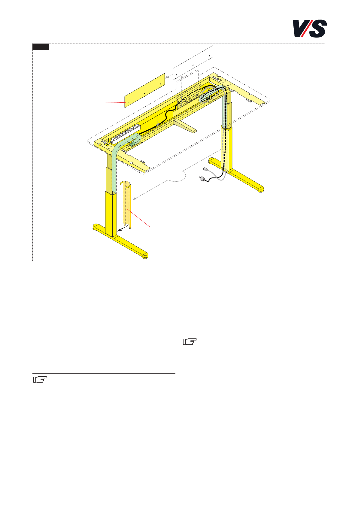
Removing the rising duct.
Pull off rising duct (1) from the table leg and unclip cable
chain (2). Gently press the cable chain together and lift out
[Fig. 1].
Inserting additional cables.
Open strain-relief devices (3) of the cable guide. Pull the ca-
ble chain with cable out of the cable tray and lay with the
opening facing upwards on the floor [Fig. 2].
Inserting an additional cable [Fig. 3].
Press the additional cable into the cable chain. Make sure
that the plug type is on the correct side and the segments of
the cable chain are uniformly closed!
Inserting several additional cables
[Fig. 3] + [Fig. 4].
Remove all cables from the cable chain. Insert new and
old cables together in threading aid (4) and pull through
the cable chain. Make sure that the plug types are on the
correct side [Fig. 3] and allow for excess cable lengths.
Important! Always start on the side
with hook (5).
Important! The excess lengths can only be corrected
when the cable chain is lying horizontal!
Installing the cable chain.
Re-straighten overkinked cable-chain links and segments
and insert the cable chain into the cable-tray chamber.
Here the opening of the cable chain must point downwards.
Guide the cable chain in the cable tray in the loop. Clip in
the hook on slot (6) and secure the cable with strain-relief
device (3). Make sure the cable chain can run freely
Installing the rising duct
(position of rising duct on right) [Fig. 1].
Feed the cable into the two cable clips on the rising duct.
Hook the rising duct with hook at the bottom into the skid
and clip at the top with the plastic retainer to the leg/post.
Clip the end of the cable chain into rising duct (7) .

7
1
(2)
(1)
Cabling the user cables [Fig. 1].
Connect the power cables to the socket strips. To do so, if
necessary release the socket panel by means of the two
knurled screws. To exchange the socket strip, press the 4 ou-
ter knobs on the fixed socket strip to release, then snap into
place again.
Insert separator (2) to separate cables and cable guide by
means of hooks and slots.
Engaging the cable tray.
First engage the cable tray at the rear and then press the cable
tray upwards until the locking bolt locks automatically!
Important! Make sure the cable
chain can run freely
Repositioning the cable chain
and rising duct.
If the cable feeds and rising duct (1) on the table are to be
repositioned from the right side to the left side (or vice versa),
the cable chain must be turned!
For the order of the individual assembly steps, see above.
However, the necessary excess lengths are different.
Important! Insert separator (2) on the other side.
Make sure the chain can run freely.
On the internet:
Alternatively, they can be downloaded: (see header title).
Troubleshooting and service:
If faults occur, please contact our
Forwarding:
Also pass on these assembly instructions if the product is
forwarded to another party.

8
Table of contents
Languages:
Other VS Desktop manuals
Popular Desktop manuals by other brands

Werner
Werner PROPLUS Base Pack 1 instruction manual

Lenovo
Lenovo ThinkCentre M625q 10TG User guide and hardware maintenance manual

IEI Technology
IEI Technology DRPC-120-BTi user manual

IBM
IBM NetVista A20 Guida per l'utente

MSI
MSI MEG Trident X User manual - quick guide

Dell
Dell Precision R5400 Technical guide