VSE.flow VSI User manual

1
Grey cast iron version Stainless steel version
VSE Volumentechnik GmbH
Hönnestrasse 47
58809 Neuenrade Germany
Phone + 49 (0)23 94 / 616 30
Fax + 49 (0)23 94 / 616 33
e-mail info@vse-flow.com
Internet www.vse-flow.com
OPERATING MANUAL
for flow meters of the product line:
„VSI High Definition Flow Meter“

2

3
Table of Contents
Page
Function description flow meter . . . . . . . . . . . . . . . . . . . . . . . . . . . . . . . . . . . . . . . . . . . . . . . . . . 4
General description . . . . . . . . . . . . . . . . . . . . . . . . . . . . . . . . . . . . . . . . . . . . . . . . . . . . . . . . . . . 4
Flow meter selection . . . . . . . . . . . . . . . . . . . . . . . . . . . . . . . . . . . . . . . . . . . . . . . . . . . . . . . . . . . 4
Declaration of Conformity . . . . . . . . . . . . . . . . . . . . . . . . . . . . . . . . . . . . . . . . . . . . . . . . . . . . . . 4
General conditions for initial start-up . . . . . . . . . . . . . . . . . . . . . . . . . . . . . . . . . . . . . . . . . . . . . 4
Maximum operating pressure . . . . . . . . . . . . . . . . . . . . . . . . . . . . . . . . . . . . . . . . . . . . . . . . . . . 5
Flow meter range . . . . . . . . . . . . . . . . . . . . . . . . . . . . . . . . . . . . . . . . . . . . . . . . . . . . . . . . . . . . . 5
Assembly of the flow meter . . . . . . . . . . . . . . . . . . . . . . . . . . . . . . . . . . . . . . . . . . . . . . . . . . . . . 6
Cleaning and flushing of pipe lines before initial start-up . . . . . . . . . . . . . . . . . . . . . . . . . . . . . 7
Filtering of liquid . . . . . . . . . . . . . . . . . . . . . . . . . . . . . . . . . . . . . . . . . . . . . . . . . . . . . . . . . . . . . . 7
Flow meters with high definition of volume measurement . . . . . . . . . . . . . . . . . . . . . . . . . . . . . . 8
Technical specifications of pre-amplifier . . . . . . . . . . . . . . . . . . . . . . . . . . . . . . . . . . . . . . . . . 13
Plug assignment of pre-amplifier . . . . . . . . . . . . . . . . . . . . . . . . . . . . . . . . . . . . . . . . . . . . . . . 14
Maintenance . . . . . . . . . . . . . . . . . . . . . . . . . . . . . . . . . . . . . . . . . . . . . . . . . . . . . . . . . . . . . . 14
Sending back of repairs and sample devices . . . . . . . . . . . . . . . . . . . . . . . . . . . . . . . . . . . . . . 15
Technical specifications VSI 0.02 / IPF – VSI 4 / IPF . . . . . . . . . . . . . . . . . . . . . . . . . . . . . . . 15
Flow response curves VSI 0.02 – VSI 4 . . . . . . . . . . . . . . . . . . . . . . . . . . . . . . . . . . . . . . . . . . 16
Dimensions VSI 0.02 – VSI 4 . . . . . . . . . . . . . . . . . . . . . . . . . . . . . . . . . . . . . . . . . . . . . . . . . . 17
Dimensions, subplate AP. 02 - 4 . . . . . . . . . . . . . . . . . . . . . . . . . . . . . . . . . . . . . . . . . . . . . . . . 18
Technical specifications VSI 10 / IPF . . . . . . . . . . . . . . . . . . . . . . . . . . . . . . . . . . . . . . . . . . . . 19
Flow response curves VSI 10 . . . . . . . . . . . . . . . . . . . . . . . . . . . . . . . . . . . . . . . . . . . . . . . . . . 19
Dimensions VSI 10 . . . . . . . . . . . . . . . . . . . . . . . . . . . . . . . . . . . . . . . . . . . . . . . . . . . . . . . . . . . 20
Dimensions, subplate APG10. . . . . . . . . . . . . . . . . . . . . . . . . . . . . . . . . . . . . . . . . . . . . . . . . . . 20
Type key . . . 21
Plug assignment . . . . . . . . . . . . . . . . . . . . . . . . . . . . . . . . . . . . . . . . . . . . . . . . . . . . . . . . . . . . . 22
Pre-amplifier - block wiring diagram . . . . . . . . . . . . . . . . . . . . . . . . . . . . . . . . . . . . . . . . . . . . . 23
Connection diagram . . . . . . . . . . . . . . . . . . . . . . . . . . . . . . . . . . . . . . . . . . . . . . . . . . . . . . . . . 23

4
1. The process fluid
‹ Is the flow meter suitable for the medium?
‹ Is the fluid viscous or abrasive?
‹ Is the fluid contaminated or is there solid matter in the fluid?
‹ Which granular size does the solid matter possess and can it block the meter?
‹ Does the fluid have fillers or other additional material?
‹ Is it necessary to install a pre-switched hydraulic filter?
‹ Are the pipe lines clean and free of assembly residues such as swarf, weld chips?
‹ Is the tank clean and is it ensured that no extraneous materials can get into the pipe-line system from the tank?
‹ Is the fluid often changed and is sufficient flushing performed in this case?
‹ Are the pipe lines and the entire system completely de-aerated?
‹ What cleaning agent is being used?
‹ Are the fluid and the cleaning agent compatible with the seals?
‹ Are the seals suitable for the fluid undergoing measurement (seal compatibility)?
Operating manual – no.: E060024 (E)
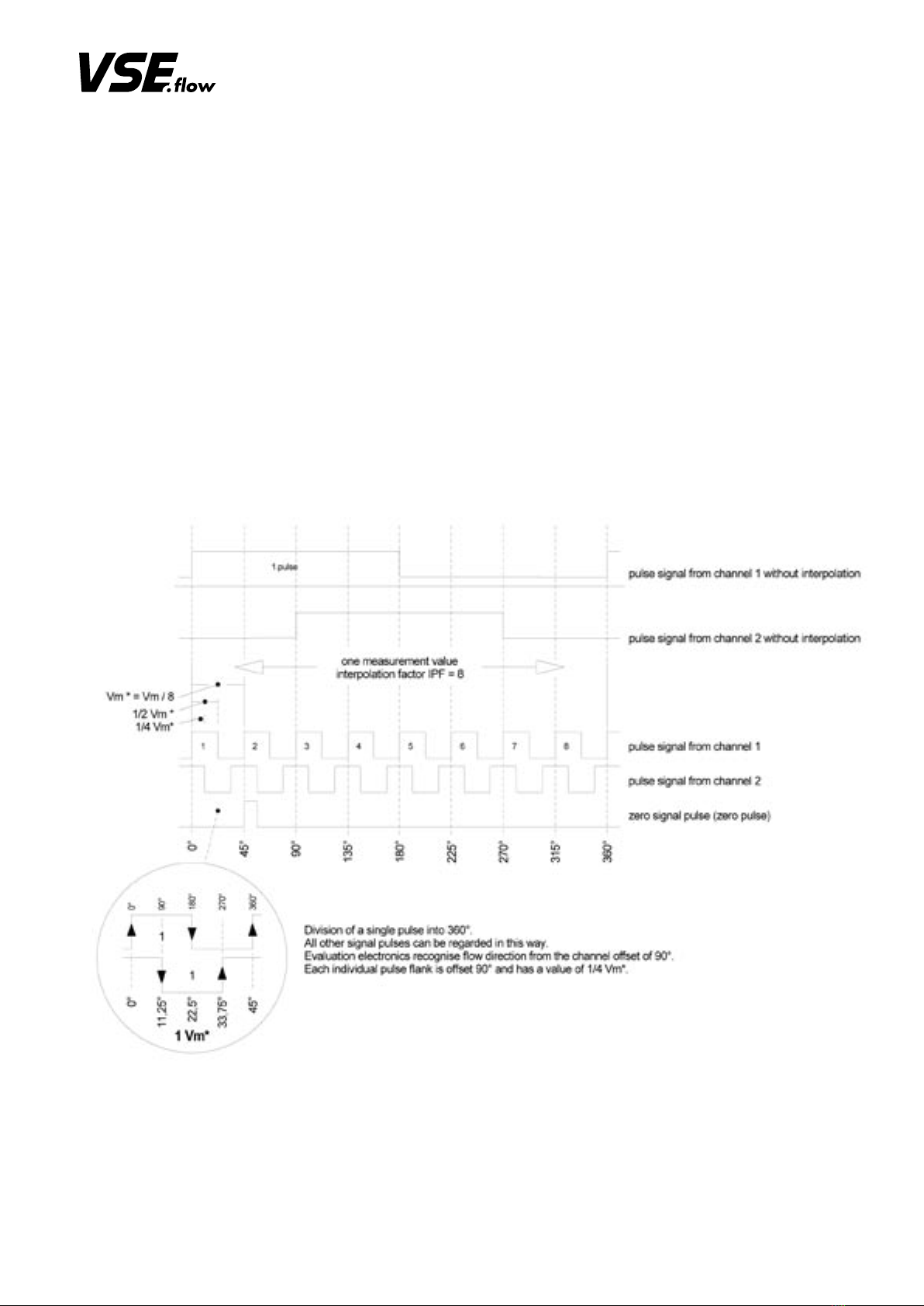
Flow meters made by VSE Volumentechnik GmbH measure the volume
flow of liquids according to the toothed wheel principle. A pair of very pre-
cisely adjusted toothed wheels in the housing constitutes the meter. A signal
pick-up system registers meter rotation free of contact and tooth by tooth.
In flow meters of high resolution (VSI), each tooth is output as a multiple of
digital pulses, depending on interpolation setting.
The gaps in the teeth of the meter wheels form meter chambers in the areas
in which they are completely enclosed by the housing walls; these cham-
bers digitalise liquid flow depending on their chamber volume.
The liquid flow within one meter rotation of a tooth division is divided by
the set interpolation factor. This gives the volume measurement per pulse
(Vm) and is defined in cm3/pulse. It identifies the constructional size of a
flow meter (e.g. VSI 1/16).
• General description
Please observe all instructions in this operating manual; only this guaran-
tees trouble-free operation of the flow meters.
VSE is not liable for any damage ensuing from non-observation of these
instructions.
Opening the devices during the term of guarantee is only authorised after
consultation and approval of VSE.
• Flow meter selection
The correct selection (version) of type and constructional size is
crucial for a trouble-free and safe operation of the flow meters.
Owing to the great number of various applications and flow meter
versions, the technical specifications in the VSE catalogue material
are of a general nature. Performance of the flow meter depends on
type, size and meter range and on the liquid that is to be measured.
Please consult VSE for an exact description.
• Declaration of Conformity
Flow meters of the “VSI” product line are tested for their electro-magnetic
compatibility and interference transmission in terms of the law on electro-
magnetic compatibility and correspond to the legal prescriptions enforced
by EMC directives. They may not be operated independently and are to be
connected via cable to a power source and supply digital electric signals
for electronic evaluation. A declaration of conformity is submitted for all
flow meters, which you can request if you require.
Since the electro-magnetic compatibility of the total measuring sys-
tem depends as well on cable layout, correct connection of protec-
tive shielding and each single connected device, you must ensure
that all components correspond to the electromagnetic compatibili-
ty directives and that the electromagnetic compatibility of the total
system, machine or plant is guaranteed.
All flow meters are tested according to the valid, legally prescribed electro-
magnetic compatibility directives EN 55011 and EN 61000 and possess
the CE certification. The EC declaration of conformity is the CE label at-
tached to all flow meters.
• General conditions for initial start-up
Before assembly and before initial start-up, you have to note the following
properties and aspects of the corresponding characteristics of your system,
so that a trouble-free and safe operation is possible.
• General function description of flow meter

5
2. The hydraulic properties of the system
‹ Is the max. operating pressure of the system lower than the max. permitted operating pressure of the flow meter?
‹ Is the max. fall of pressure ∆p (on flow meter) below the max. permitted fall of pressure?
‹ Does an excessively great fall in pressure ∆p occur on the flow meter at max. flow (e.g. with higher viscosity)
‹ Does the flow range of the flow meter (depending on viscosity) correspond to the provided flow?
‹ Note that flow range decreases the greater the viscosity!
‹ Does the temperature range of the flow meter correspond to the provided max. temperature of the medium?
‹ Is the cross section of the pipe line large enough and are the falls in pressure in the system not excessive?
‹ Is the hydraulic connection (supply and reverse flow) correctly connected and leak-proof?
‹ Has the pump sufficient power to operate the system?
‹ A blocking flow meter can stop the whole flow. Is a pressure control valve / bypass provided in the system?
• Maximum operating pressure
Before assembling the flow meter, you have to test that the max. operating
pressure of the system does not exceed the max. permitted operating pres-
sure of the flow meter. Meanwhile, observe the top pressures that can occur
when operating the system.
3. Electronic evaluation and electrical safety
‹ Have you selected the optimal flow meter and is this equipped with the appropriate pre-amplifier?
‹ Does the power supply voltage of the flow meter correspond to the provided voltage?
‹ Is the power supply voltage supplied by the mains or evaluation device sufficiently steady?
‹ Does the output of the power supply voltage correspond to the required power output?
‹ Has the electric connection been installed based on the enclosed connection plan?
‹ Is the cable protective shielding correctly connected on both sides on the earth conductor PE?
‹ Is there a potential difference between the earth conductor connection PE on the flow meter and the earth con-ductor PE on the evaluation
device?
‹ Does a correcting lead have to be laid to eliminate the potential difference between the flow meter and the evaluation device?
‹ Is the flow meter connected firmly to the earth conductor PE (e.g. via the pipe lines)
‹ Is the meter of the flow meter constructed to be insulated to the earth conductor PE (e.g. connection via hoses)? If this is the case, the meter
has to be connected with the earth conductor PE!
‹ Is there a continuous connection of the cable protective shielding (earth conductor PE) via the housing, of the 4 or 5-pin round plug to the
meter of the flow meter?
‹ Is the cable laid fault-free and the installation secured from input of interference pulses?
‹ Is the 4 or 5-pin round plug of the connection cable firmly screwed together with the plug of the flow meter?
‹ Are the wires on the evaluation device correctly and properly connected?
‹ Does the entire system correspond to the directives of the electro-magnetic compatibility laws (EMC)?
‹ Have all local valid regulations, applicable directives, guidelines and background conditions of the electro-magnetic compatibility laws
been maintained and observed?
‹ Systems that can lead to personal injury through malfunction or failure are to be equipped with the appropriate safety devices. The functioning
of these safety devices is to be checked at regular intervals.
The following operating pressures are permitted depending on flow meter
version:
‹ Flow meter in grey cast iron version pmax = 315 bar
‹ Flow meter in stainless steel version pmax = 450 bar
‹ Flow meter in special version pmax= up to 700 bar
Important:
Please consult VSE for all operating pressures > 450 bar and for special versions.
• Flow meter range
The flow meter range specified in the flow meter data sheet (Qmin - Qmax)
refers to the testing fluid‚ hydraulic oil‘ with a viscosity of 21 mm2/s at a
temperature of 20 °C. For this flow meter range, VSE specifies measure-
ment accuracy of up to 0.3 % of the measurement value and a repetition
accuracy of 0.05 %.
For fluids of lower viscosity (< 21 mm2/s) measurement accuracy deteri-
orates, while for fluids of higher viscosity (> 21 mm2/s) it can improve.
Also note, however, that the flow meter range is restricted in case of higher
viscosity (see flow meter data sheet).

6
• Assembly of the flow meter
The flow meter should be mounted on an easily accessible location, so that
dismantling for cleaning the meter presents no problem. Since flow meters
can work in any installation position and flow direction, you can mount it on
any location of your system that you wish. Take care when installing the flow
meter that liquid always remains in the flow meter even at system standstill
and that it can never run empty. The outflow of the flow meter should there-
fore always show a certain back pressure, since this clamps the flow meter
meter firmly in the liquid column (the meter supports itself through this on the
liquid column) and the pipe line cannot run empty. In critical cases or when
the pipe line is at standstill or standby and can run empty, we recommend
installing an extra non-return valve in the outflow line.
Flow meters of the “VSI” product line can be mounted directly onto a block
or into the pipe line using four screws. Always select large cross sections
for the hydraulic supply and return flow respectively for the entire pipe-line
system (if possible). This lowers the fall in pressure and the flow rate in the
total system.
Important:
Make sure that the specified maximum permitted operating pressure of the flow meter
cannot be exceeded, whatever the operating mode of the system. Note the flow meter
range that is dependent on the viscosity of the fluid to be measured.
Important:
Make sure that the flow meter is always completely filled both in inflow and outflow
and that the outflow has a little back pressure. This prevents the meter being damaged by
a sudden and steep increase of flow and at the same time improves measurement accuracy.
Fig. 1: Flow meter installation with non-return valve
Flow meter, size (cast iron and 1.4305) Torque
VSI 0.02; VSI 0.04; VSI 0.1; VSI 0.2 40 Nm
VSI 0.4; VSI 1; VSI 2 70 Nm
VSI 4 120 Nm
VSI 10 280 Nm
VSE supplies subplates for all flow meters of the “VSI” product line; they
have various pipe threads and side or rear-side connection (see subplates
data sheet). Depending on the provided conditions, the installed pipe line,
the pipe cross section or pipe thread, the operator can choose the suitable
subplate and incorporate this into the system or machine without additional
reductions.
The flow meter is screwed onto the block or subplate with four DIN 912
cheese head screws. The screws are to be evenly pre-tensed crosswise with
the following torques.
When changing the fastening screws you must take great care that the
screws are of property class 10.9 and 12.9.
Block assembly:
The flow meter is directly mounted onto a subplate or manifold, extra
components are not needed. The block contains the hydraulic supply and
outflow of the flow meter and the fixing bore holes (see flow meter
dimension sheet).
Table 1: Torque of fastening screws
Please note the special instructions for mounting sizes VSI 4 and VSI 10
(see appendix)

7
• Filtering of liquid
Strongly contaminated fluids or extraneous material in the fluid can block,
damage or even destroy the flow meter. Always install a sufficiently large
filter for these cases in front of the flow meter to prevent damage to the
flow meter. The necessary filtering depends on size, storage and model
of flow meter.
Important:
Please flush out the pipe lines and the tank thoroughly, to prevent contamination
within the flow meter.
Important:
When mounting the flow meter, you must take great care that the seals are not damaged and
correctly placed in the hydraulic connections of the flow meter. Wrongly installed or dama-
ged seals lead to leakage and to an leaky system, which may have dire consequences.
Please make sure that flow meters with EPDM seals do not come into contact with oil and
greases on a mineral oil basis. These fluids can decompose the seals.
The yellow plastic plugs in the hydraulic connections of the flow meter protect the meter
against dirt and contamination during storage and shipping. Before mounting the flow meter
you have to remove these plugs so that in- and outflow is free and open.
• Cleaning and flushing of pipe lines before initial start-up
Before initial start-up of the flow meter, you must flush and clean the whole
system. Contaminated fluid can effect the correct function of the flow meter
or seriously damage the meter.
After preparing and connecting up the system pipes, you must first carefully
flush and clean the whole pipe-line system and the tank. To do this, you
have to mount a diversion plate onto the block or connection plate instead
of the flow meter, so that the fluid can flow through the diversion plate and
all extraneous material (e.g. swarf, metal chips, etc.) can be flushed out
without obstruction. Use a fluid as cleansing agent which is compatible with
the fluid being used later and which does not cause undesirable reactions.
You can consult the suppliers and manufacturers of the fluid or contact VSE
for the corresponding information. VSE supplies bypass plates for all VSI-
flow meter sizes.
Flow meters are measurement pick-up systems made with high-level preci-
sion. They have a mechanical meter consisting of two toothed wheels and
which is adapted to the housing with narrow slots. Even the tiniest damage
to the toothed wheels and bearings can cause a measurement error. So
always make sure that no extraneous material gets into the meter and that
the fluid flowing through is always free from dirt and contamination.
After the system has been carefully flushed out and no extraneous material
is in the pipe line, you can mount the flow meter and commence the initial
start-up.
Flow meter size Filter size for ball bearings
VSI 0.02 / 0.04 / 0.1 10 µm
VSI 0.2 / 0.4 20 µm
VSI 1 / 2 / 4 / 10 50 µm
Table 2: Pre-switched filters
For information on filter size for flow meters with plain bearings, in spe-
cial version, or with specially adjusted meter tolerances, please consult
VSE GmbH.
Important:
A blocking flow meter can stop the whole flow. You have to provide a control
valve / bypass for the system.

8
The pre-amplifiers of the standard version for flow meters of the “VS” pro-
duct line output a pulse per tooth-gap volume VZ, which corresponds to
the volume measurement Vm (Vm = VZ / pulse.). This takes place in two
channels, so that you can attain a maximum resolution of 1/4 VZ for the
evaluation of all flanks. A higher resolution is not possible with these pre-
amplifiers.
But since as high a resolution as possible is necessary for precise and ex-
act flow and volume measurements, the volume measurement Vm must be
resolved even more than is the case with conventional pre-amplifiers. VSE
has therefore developed the pre-amplifier with interpolation, with which a
selectable resolution of up to 64 flanks (16 pulses) per period can be attai-
ned (see table 3). This means that you can resolve the volume measurement
Vm with this pre-amplifier to a maximum of 1/64 Vm. For the evaluation, this
means that a part volume of 1/64 Vm from pulse flank to pulse flank (for
quadruple evaluation or flank count) is measured, or a full signal pulse is
counted as part volume of 1/16 Vm (pulse count) (see Fig. 3, interpolation
Vm/16).
This individually programmed high resolution enables you to set the vo-
lume measurement Vm optimally for each provided case of application.
Furthermore, new applications can be availed of with the higher resolution
Fig. 2 shows the resolution of the volume measurement Vm with an interpola-
tion factor of 8. This resolves each volume measurement into eight individu-
al part volumes. A pulse on the signal output of channel 1 or channel 2 thus
has a value of Vm* = Vm / 8 = 1/8 Vm per pulse. In double evaluation (flank
evaluation of one channel) this results in a value of 1/2 Vm* = Vm / 16 =
1/16 Vm and for quadruple evaluation (flank evaluation of both channels)
the result is a value of 1/4 Vm* = Vm / 32 = 1/32 Vm per flank. Evaluation
electronics can recognise flow direction from signals offset 90°.
• Flow meters with high definition of volume measurement
‹ Measuring, controlling and regulating in the lower flow range
‹ Measuring, controlling and regulating in zero flow
‹ Measuring, controlling and regulating in both flow directions
‹ Measuring, controlling, dosing and filling of small volumes
Flow meters with interpolation electronics (VSI) output two digital signals
with programmable high resolution that are phase-offset 90° (see Fig. 3).
In addition to the signal emission, a zero signal emission is provided which
emits a zero signal at each fully registered volume measurement Vm (see
Fig. 2).
Fig. 2: Signal emission of the pre-amplifier with interpolation
(interpolation factor 8)

9
The pre-amplifier of the “VSI” product line has a programmed interpolation
factor (IPF) with which you can program new, different resolutions. Hence
you can program a resolution of 4 to 64 angular steps (see Fig. 4) per
volume measurement Vm. The frequency multiplication “f*” lies between 1
and 16 (see Table 3).
Column 1: Programmable interpolation factor IPF (programming is done in the factory)
Column 2: Pulses per volume measurement Vm
Column 3: Maximum resolution of the signal flanks. The signal flanks of channels 1 and 2 are evaluated.
Column 4: Volume measurement Vm* resulting from the maximum resolution of the signal flanks.
Column 5: Maximum resolution in angle degrees at resolution of signal flanks.
Column 6: Maximum frequency fmax* at maximum flow Qmax and programmed interpolation factor IPF
In practice, the maximum flow Qmax of the flow meter is seldom run, so that a lower frequency can be calculated. The maximum frequency is then calcu-
lated according to the following formula:
fmax
° Maximum frequency of the flow meter signals
Qmax
° Maximum flow attained in the case of application described here
IPF Programmed interpolation factor
Vm Volume measurement of the flow meter
Example: Flow meter VSI 1/10… max. flow the system can be run on at a maximum
Qmax
° = 40 l/min = 666.667 ml/sec; IPF = 10; Vm = 1 ml/pulse; fmax
° = 6666.67 Hz = 6.66667 kHz
At max. flowmax
° = 40 l/min, the flow meter VSI 1/10… outputs a frequency of fmax
° = 6666.67 Hz.
Interpolation
factor
Pulse/VmMax. resolution
(evaluation of signal
flanks)
Resolution Vm*
(volume measure-
ment Vm*)
[ml]
Max. resolution
(angle degrees)
Frequency fmax*
1 1 4 (quadrupling) Vm / 4 90° fmax x 1
2 2 8 Vm / 8 45° fmax x 2
3 3 12 Vm /12 30° fmax x 3
4 4 16 Vm /16 22.5° fmax x 4
5 5 20 Vm /20 18° fmax x 5
8 8 32 Vm /32 11.25° fmax x 8
10 10 40 Vm /40 9° fmax x 10
12 12 48 Vm /48 7.5° fmax x 12
16 16 64 Vm /64 5.625° fmax x 16
Table 3: Interpolation factor and resolution
Only the marked lines are illustrated in the diagram of Fig. 3
fmax
°=(Qmax
°)*IPF Formula 1
Vm

10
Fig. 3: Interpolation of the volume measurement Vm
Important:
Test the connected evaluation electronic system as to whether it can process the maximum
frequency fmax* of the flow meter. Check the data from the following table for the relevant
flow meter, or calculate the maximum frequency data fmax° with formula 1.
At initial start-up of the system, you have to program the volume measu-
rement Vm* (see Table 4, column 4) in your evaluation electronics as
parameter value (e.g. multiplier). The evaluation electronics then multiply
every pulse the flow meter outputs by the volume measurement Vm* and
thus calculates the flow and the volume. For flow meters with high resolu-
tion, the parameter value volume measurement Vm* is dependent on
volume measurement Vm (see Table 4, column 2) and on the programmed
interpolation factor IPF (see Table 4, column 3).
Please consult this first of all for the volume measurement Vm* and program
this value as parameter into your evaluation electronics.
On Table 4 you can view the corresponding volume measurement Vm* (see
Table 4, column 4) with the real, programmed interpolation factor IPF*
(see Table 4, column 3). The R-factor in column 5 is a measurement for the
resolution per litre.
You then get the maximum frequency fmax* (see Table 4, column 8) of the
signal pulses for the maximum flow Qmax (see Table 4, column 6) with
programmed interpolation factor IPF*. This frequency is dependent on the
programmed interpolation factor IPF and increases with rising resolution.
.
.

11
Table 4: Volume measurement and max. frequency at high resolution
Flow meter Vol. measurement
Vm
Interpol.
IPF*
Vol. measure-
ment Vm*
(ml/pulse)
R-factor*
(pulse/l)
Qmax fmax fmax*
(Hz)
VSI 0.02… 0.02 ml/pulse 1 0.02 50 000 2 l/min
(= 2 000 ml/min
= 33.33 ml/s)
1 666.7 Hz 1 666.7
2 0.01 100 000 3 333.3
3 0.00666667 150 000 5 000.0
4 0.005 200 000 6 666.7
5 0.004 250 000 8 333.3
8 0.0025 400 000 13 333.3
10 0.002 500 000 16.666.7
12 0.00166667 600 000 20 000.0
16 0.00125 800 000 26 666.7
VSI 0.04… 0.04 ml/pulse 1 0.04 25 000 4 l/min
(= 4 000 ml/min
= 66.67 ml/s)
1 666.7 Hz 1 666.7
2 0.02 50 000 3 333.3
3 0.01333333 75 000 5 000.0
4 0.01 100 000 6 666.7
5 0.008 125 000 8 333.3
8 0.005 200 000 13 333.3
10 0.004 250 000 16.666.7
12 0.00333333 300 000 20 000.0
16 0.0025 400 000 26 666.7
VSI 0.1… 0.1 ml/pulse 1 0.1 10 000 10 l/min
(= 10 000 ml/min
= 166.67 ml/s)
1 666.7 Hz 1 666.7
2 0.05 20 000 3 333.3
3 0.03333333 30 000 5 000.0
4 0.025 40 000 6 666.7
5 0.02 50 000 8 333.3
8 0.0125 80 000 13 333.3
10 0.01 100 000 16.666.7
12 0.00833333 120 000 20 000.0
16 0.00625 160 000 26 666.7
VSI 0.2… 0.2 ml/pulse 1 0.2 5 000 18 l/min
(= 18 000 ml/min
= 300 ml/s)
1 500 Hz 1 500.0
2 0.1 10 000 3 000.0
3 0.06666667 15 000 4 500.0
4 0.05 20 000 6 000.0
5 0.04 25 000 7 500.0
8 0.025 40 000 12 000.0
10 0.02 50 000 15 000.0
12 0.01666667 60 000 18 000.0
16 0.0125 80 000 24 000.0
VSI 0.4… 0.4 ml/pulse 1 0.4 2 500 40 l/min
(= 40 000 ml/min
= 666.7 ml/s)
1 666.7 Hz 1 666.7
2 0.2 5 000 3 333.3
3 0.13333333 7 500 5 000.0
4 0.1 10 000 6 666.7
5 0.08 12 500 8 333.3
8 0.05 20 000 13 333.3
10 0.04 25 000 16.666.7
12 0.03333333 30 000 20 000.0
16 0.025 40 000 26 666.7

12
Flow meter Vol. measurement
Vm
Interpol.
IPF*
Vol. measure-
ment Vm*
(ml/pulse)
R-factor*
(pulse/l)
Qmax fmax fmax*
(Hz)
VSI 1… 1 ml/pulse 1 1.0 1 000 80 l/min
(= 80 000 ml/min
= 1 333.3 ml/s)
1 333.3 Hz 1 333.3
2 0.5 2 000 2 666.7
3 0.33333333 3 000 4 000.0
4 0.25 4 000 5 333.3
5 0.2 5 000 6 666.7
8 0.125 8 000 10 666.7
10 0.1 10 000 13 333.3
12 0.08333333 12 000 16 000.0
16 0.0625 16 000 21 333.3
VSI 2… 2 ml/pulse 1 2.0 500 120 l/min
(= 150 000 ml/min
= 2 500 ml/s)
1 000 Hz 1 000.0
2 1.0 1 000 2 000.0
3 0.66666667 1 500 3 000.0
4 0.5 2 000 4 000.0
5 0.4 2 500 5 000.0
8 0.25 4 000 8 000.0
10 0.2 5 000 10 000.0
12 0.16666667 6 000 12 000.0
16 0.125 8 000 16 000.0
VSI 4… 4 ml/pulse 1 4.0 250 250 l/min
(= 300 000 ml/min
= 5 000 ml/s)
1 041.7 Hz 1 041.7
2 2.0 500 2 083.3
3 1.33333333 750 3 125.0
4 1.0 1 000 4 166.7
5 0.8 1 250 5 208.3
8 0.5 2 000 8 333.3
10 0.4 2 500 10 416.7
12 0.33333333 3 000 12 500.0
16 0.25 4 000 16 666.7
VSI 10… 3.33 ml/pulse 1 3.33333333 300 525 l/min
(= 525 000 ml/min
= 8 750 ml/s)
2 625 Hz 1 500.0
2 1.66666667 600 3 000.0
3 1.11111111 900 4 500.0
4 0.83333333 1 200 6 000.0
5 0.66666666 1 500 7 500.0
8 0.41666666 2 400 12 000.0
10 0.33333333 3 000 15 000.0
12 0.27777777 3 600 18 000.0
16 0.20833333 4 800 24 000.0
Vm = physical volume measurement (size) of the flow meter (volume per tooth and per tooth gap)
Qmax = max. flow (test conditions)
fmax = max. frequency at Qmax fmax = Qmax / Vm
IPF* = programmable interpolation factor
* = all characters marked with * refer to IPF*
Vm* = interpolated volume measurement Vm* = Vm / IPF* ; K-factor* = 1 / Vm*
fmax* = max. interpolated frequency at Qmax fmax* = Qmax / Vm*

13
Example of flow meter “VSI 0,1/10 …”
1. Column : Flow meter, version VSI and size 0.1 VSI 0.1…
2. Column: physical volume measurement Vm Vm = 0.1 ml/pulse
(corresponds to the volume measurement Vm at interpolation factor IPF* = 1)
3. Column: Interpolation factor IPF* = hardware programmed IPF* = 10
4. Column: Volume measurement Vm* Vm* = 0.01 ml/pulse
5. Column: K-factor* ; reciprocal value of volume measurement Vm* K-factor* = 100 000 pulse/l
6. Column: maximum flow Qmax of the flow meter Qmax = 10 l/min
7. Column: maximum frequency fmax at interpolation factor IPF = 1 (see column 2) fmax = 1 666.7 Hz
(corresponds to the volume measurement Vm at interpolation factor IPF = 1)
8. Column: maximum frequency fmax* at programmed interpolation factor (see column 3) fmax* = 16 666.7 Hz
The high-level stages of the pre-amplifier are fast line drivers for three chan-
nels with a characteristic wave impedance adjustment for 75Ω lines. They
emit the signals of channel A, channel B and the zero channel Z. The push-
pull high-level stages are designed for high driver power of approx. 300
mA on 24 V; they are current limiting and short-circuit-proof by switch-off
at excessive temperature. Cap diodes against Vb and against GND pro-
tect the emittance against “echoes” through erroneously adjusted lines and
against destruction through ESD.
A switching circuit in the high-level stage monitors the voltage supply Ub as
well a the temperature and in case of error switches all high-level stages to
high impedance. The error output is designed as open collector and likewi-
se short-circuit-proof; it sends an error message to the external electronics
if there is a malfunction.
Data transfer with 24 V signals is done as a rule without circuit termination
with a wave impedance. An erroneously ad-justed circuit termination cau-
ses reflections which can run repeatedly hither and thither if no adjustment
is provided on the sender side. If there is a fast sequence of pulses, trans-
mission is interfered with by these reflections.
If there are long connection lines between the pre-amplifier and the evalu-
ation electronics and also a high resolution, lines with a wave impedance
of approx. 40Ω to 150Ω should be used and a corresponding termination
impedance connected to the evaluation electronics. An optimal adjustment
of the transmission line and the termination wave impedances can permit
line lengths of up to approx. 150 … 200 m.
High interference protection is achieved by a large output amplitude and
by the integrated wave adjustment. When the signals on the receiver side
are guided through optp-couplers, you furthermore get a galvanic separa-
tion between sender and receiver side and potential differences can thus
be avoided.
The reflection of return signals is prevented in the high-level stage of the
pre-amplifier by an integrated wave impedance adjustment. This adjust-
ment enhances interference-proof performance.
Scan sensor: GMR sensor with diplexer; or other scan sensors which supply a sine and cosine signal;
Number of sensors: Two scan sensors for generating the sine and cosine signal;
Adjustment: Offset adjustment by means of two potentiometers;
Resolution: programmable in a range of 1 – 64 flanks per volume measurement Vm;
Frequency: Frequency multiplication: programmable in a range of 1 – 16 times the frequency of the scan sensors.
Emission signals: Channel A, channel B, zero channel Z
Channel A and B: Two signal outputs for emitting the digital flow sensor signals; between channel A and channel B there is a channel offset of 90°;
Flow direction: Recognition of flow direction from channel offset of the signals from channel A to channel B.
Zero signal Z: Zero signal, marks the flow of one volume measurement Vm;
Outputs: 3 current limiting and short-circuit-proof high-level stages (channel A, channel B, zero signal Z); integrated adjustment to a 75Ω
wave impedance; driver current approx. 300 mA at 24 V power supply; small saturation voltage up to 30mA load current; short
switching times; integrated free-run diodes against Vb and GND; temperature protection switching with hysteresis; outputs are of
high impedance in case of error;
The 24 V line drivers are designed for control technology with cable adjustment;
Error messages: Short-circuit-proof output for issuing error messages at excessive temperature or low voltage, low active
operating voltage: Vb = 8 … 30 VDC
Current consumption: Ino load = approx. 40 mA; total current consumption depending on loading of outputs;
• Technical specifications of pre-amplifier
The present specifications apply to a newly developed product. We there-
fore reserve the right to modify data without further announcement. If need
be, contact us in order to find out the updated data. The specified data is
for product description and is not to be interpreted as a verified characte-
ristic in the legal sense. We are not liable for any damage compensation
claims against us – regardless of the legal grounds – unless charges of
intention of such or gross neglect apply.
We do not assume any guarantee that the specified control or the process
is free of industrial rights of a third party. Copying the document – also ex-
cerpts – is only permitted with authorisation of the editor and with precise
specification of source.

14
Fig. 4 shows the plug assignment of the pre-amplifier. As you can see, this
plug has four pins, the outer four assigned exactly as the ones in standard
pre-amplifiers. In addition to the power supply and signal output of channel
1 and 2, there is a fifth pin which emits the zero signal.
As a rule, only the four outer pins are needed to evaluate the flow meter si-
gnals; pin assignment is therefore the same as in previously described pre-
amplifiers. For this reason you can use a normal 4-wired connection cable
for the connection of the flow meter. But please make sure that the shielding
of the cable is laid on the plug side onto the metal housing of the plug.
The shielding of the connection cable is placed on both sides. The earth
conductor PE is connected via the shielding from the evaluation electronics
to the pre-amplifier housing and the meter. The cable shielding should al-
ways be laid continuously as far as the flow meter and not interrupted in
cross connectors or branch sockets. Lay the connection cable as directly
as possible from the evaluating device to the flow meter, since interruptions
are always a potential source of error.
The flow meter must be connected electrically with the earth conductor PE.
This is normally secured by the earthed pipe lines.
If there are potential differences between the pre-amplifier housing
and the earth conductor PE of the evaluating electronics, you have
to lay a correcting earth.
• Plug assignment of pre-amplifier
Important:
Only use well-shielded cables for the connection cable, with a wire cross section of
≥ 4 or 5 x 0.25 mm2. Please make sure that the housing of the round plug is metallic, that it
has a connection for the shielding and that the potential of the earth conductor PE is
connected with the cable shielding and the housing of the pre-amplifier.
Important:
Please make sure that no extra inductive elements are connected in the power supply of the
flow meter, such as contactors, relays, valves, etc.
These components are potent sources of interference (especially if the inductive elements
are not provided with an adequate protective circuit), generate high interference pulses
when switched and can interfere with the functioning of the flow meter, although this
complies with the electromagnetic compatibility directives.
Working life is dependent on operating conditions and thus the specific properties of the
devices, limited through wear, corrosion, deposits or age. The operator is responsible for
regular control, maintenance and recalibration. Any indication of a malfunction or damage
prohibits any further use. On request, we can supply you with a borrowed device for the du-
ration of repair or overhauling.
• Maintenance
Fig. 4: Flange plug installed in the pre-amplifier housing of the flow meter

15
Size Measuring range
l/min
Frequency
Hz
Pulse value
cm3/pulse
R-factor
pulse/litre
VSI 0.02 0.002 … 2 1.667 * IPF … 1666.67 * IPF 0.02 / IPF 50 000 * IPF
VSI 0.04 0.004 … 4 1.667 * IPF … 1666.67 * IPF 0.04 / IPF 25 000 * IPF
VSI 0.1 0.01 … 10 1.667 * IPF … 1666.67 * IPF 0.1 / IPF 10 000 * IPF
VSI 0.2 0.02 … 18 1.667 * IPF … 1500.00 * IPF 0.2 / IPF 5 000 * IPF
VSI 0.4 0.03 … 40 1.250 * IPF … 1666.67 * IPF 0.4 / IPF 2 500 * IPF
VSI 1 0.05 … 80 0.833 * IPF … 1333.33 * IPF 1 / IPF 1 000 * IPF
VSI 2 0.1 … 120 0.833 * IPF … 1000.00 * IPF 2 / IPF 500 * IPF
VSI 4 1.0 … 250 4.167 * IPF … 1041.67 * IPF 4 / IPF 250 * IPF
Measurement accuracy : up to 0.3 % of measurement value (with viscosity > 20mm2/s)
Repetition accuracy : ± 0.05 % under the same operating conditions
Material : Cast iron EN-GJS-400-15 (EN 1563) or
stainless steel 1.4305
Meter bearing : Ball bearings or steel plain bearings (medium-dependent)
Seals : FPM (standard), NBR, PTFE or EPDM
Max. operating pressure : Cast iron EN-GJS-400-15 (EN 1563) 315 bar
stainless steel 1.4305 450 bar
Medium temperature : –40 … + 120°C (–40 °F …. 248 °F)
Ambient temperature : –20 … + 50°C (–4 °F …. 122 °F)
Viscosity range : 1 … 100 000 mm2/s
Installation position : any
Flow direction : any
Running noise : max. 72 db(A)
Power supply version : 10 to 30 volts/DC
Pulse output : 3 current limiting and short-circuit-proof high-level stages
low signal: 0 = GND; high signal: 1 = Ub -1
Channel offset : 90° ± 30° max.
Pulse-width repetition rate : 1/1 ± 15° max.
Pre-amplifier housing : Aluminium
Protection type : IP 65
It is imperative that you enclose an exact description of the complaint, ob-
jection or fault when returning the device so as to ensure a rapid and eco-
nomic repair of the flow meters and other components. Furthermore, you
must include a security sheet, which informs unambiguously which fluid was
run with the flow meter and how dangerous this fluid is.
The maintenance of legal regulations as regards work safety, such as work-
place regulations, accident prevention regulations, and stipulations on en-
vironmental protection, waste disposal and the water management law,
obliges industrial corporations to protect their employees and other per-
sons and environment against harmful effects when handling hazardous
materials. If further safety precautions are still necessary despite careful
emptying and cleaning of the flow meter, information on this is imperative
and must be included with the returned despatch.
When returning flow meters to VSE Volumentechnik GmbH, please note
that inspection and repair will only be performed if the safety specifica-
tions sheet of the utilised fluid is enclosed and the flow meters completely
cleaned and flushed. This protects our employees and simplifies our work.
If this is not observed, the despatch will be returned, chargeable to
the recipient.
• Sending back of repairs and sample devices
• Technical specifications VSI 0.02 / IPF – VSI 4 / IPF
Adjustable interpolation factors IPF: 1; 2; 3; 4; 5; 8; 10; 12; 16

16
• Flow response curves VSI 0.02 – VSI 4
..
..
.

17
• Dimensions VSI 0.02 – VSI 4
size
VSI
A B C D E øG H K L M N O-ring
GCI
kg
SS
kg
0.02 100 80 91 M6 12.0 9 114 58 70 40 20 11 x 2 2.8 3.4
0.04 100 80 92 M6 11.5 9 115 59 70 40 20 11 x 2 2.8 3.4
0.1 100 80 94 M6 9 9 117 61 70 40 20 11 x 2 2.8 3.4
0.2 100 80 94 M6 9.5 9 117 61 70 40 20 11 x 2 3.0 3.7
0.4 115 90 96.5 M8 11.5 16 120 63.5 80 38 34 17.96 x 2.62 4.0 5.0
1130 100 101 M8 12.5 16 124 68 84 72 34 17.96 x 2.62 5.3 6.8
2130 100 118 M8 15 16 141 85 84 72 34 17.96 x 2.62 6.7 8.4
4180 140 145 M12 20 30 168 110 46 95 45 36.17 x 2.62 14.7 18.4
Weight
The dimensions are in mm

18
• Dimensions, subplates AP. 02 - 4
Connection position, side
Connection position below
For size
VSI
Connection
thread
G
F øH A B C D E L Thread / depth
M
Weight
kg
0.02
0.04
0.1
0.2
G 1/4“
G 3/8“
G 1/2“
“5
20
80 90 40 70
26
100 M6 / 12 1.8
23 30
28 38
0.4 G 1/2“ 35 28 90 100 38 80 46 115 M8 /15 2.7
G 3/4“ 40 33 52
1
2
G 1/2“ 35 28
100 110 72 84
46
130 M8 /15 3.6G 3/4“ 40 33 52
G 1“ 55 41 55
4
G 1 1/4“ 70 51 120 130 100
110 60
M8 /15 7.4
*G 1 1/2“ 70 56 120 72
G 1 1/2“ 80 140 110 180 12.0
only for AP . 4 U...

19
Size Measuring range
l/min
Frequency
Hz
Pulse value
cm3/pulse
R-factor
pulse/litre
VSI 10 1.5 … 525 7.50 * IPF … 2625.67 * IPF 3.333 / IPF 300 * IPF
Measurement accuracy : up to 0.5 % of measurement value (with viscosity > 20mm2/s)
Repetition accuracy : ± 0.05 % under the same operating conditions
Material : Cast iron EN-GJS-400-15 (EN 1563)
Meter bearing : Ball bearings or steel plain bearings (medium-dependent)
Weight : 70 kg without connection plate
Seals : FPM (standard), NBR, PTFE or EPDM
Max. operating pressure : 350 bar / 5000psi
Medium temperature : –40 … + 120°C (–40 °F …. 248 °F)
Ambient temperature : –20 … + 50°C (–4 °F …. 122 °F)
Viscosity range : 5 … 100 000 mm2/s
Installation position : any
Flow direction : any
Running noise : db(A)
Power supply version : 10 to 28 volts/DC
Frequency range : 0 … 2625 Hz
Pulse output : 3 current limiting and short-circuit-proof high-level stages
low signal: 0 = GND; high signal: 1 = Ub -1
Channel offset : 90° ± 30° max.
Pulse-width repetition rate : 1/1 ± 15° max.
Pre-amplifier housing : Aluminium
Protection type : IP 65
• Technical specifications VSI 10 / IPF
Adjustable interpolation factors IPF: 1; 2; 3; 4; 5; 8; 10; 12; 16
• Flow response curves VSI 10

20
• Dimensions VSI10
APG 10 SG0N / 1
• Dimensions, subplate APG10.
APG 10 SW0N / 1
The dimensions are specified in mm
This manual suits for next models
9
Table of contents
Popular Measuring Instrument manuals by other brands

Kyoritsu Electrical Instruments Works, Ltd.
Kyoritsu Electrical Instruments Works, Ltd. KEW 2062 instruction manual

B+K precision
B+K precision 889B manual

Sensor Therm
Sensor Therm METIS M3F1 user manual

Self Climat
Self Climat Smartbox MINI Assembly and operating instructions

GreenValley
GreenValley LiAirX3-H user guide

Bin Master
Bin Master DPM-400 manual