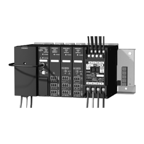
Hioki 2300 Smart Site User manual

SMART SITE
Instruction Manual
2300
February 2011 Revised edition 5 2300A981-05 11-02H

Contents
I
Contents
Introduction.................................................................................1
Safety Notes...............................................................................1
Notes on Use..............................................................................4
Service .......................................................................................7
1
2301-20 HUMIDITY MODULE___________________ 9
1.1 Overview .......................................................................9
1.1.1 Product Overview ............................................................9
1.1.2 Major Features ................................................................9
1.1.3 Name and Function of the Parts ...................................12
1.1.4 Dimension Diagrams .....................................................13
1.1.5 Accessory and Option ...................................................13
1.2 Settings .......................................................................14
1.2.1 Setting the Module ID ....................................................14
1.3 Preparations................................................................15
1.3.1 Installing the Module .....................................................15
1.3.2 Connecting Input/Output Cables ...................................16
1.4 Others .........................................................................19
1.4.1 Alarm output ..................................................................19
1.4.2 Insulation of Internal Circuit ...........................................21
1.5 Specifications..............................................................22
1.5.1 Basic Specifications ......................................................22
1.5.2 Function Specifications .................................................22
1.5.3 General Specifications ..................................................23
1.5.4 9764-50 HUMIDIDTY SENSOR Specifications .............24
2
2302-20 Pt MODULE_________________________ 25
2.1 Overview .....................................................................25
2.1.1 Product Overview ..........................................................25
2.1.2 Major Features ..............................................................25
2.1.3 Name and Function of the Parts ...................................28
2.1.4 Dimension Diagrams .....................................................29
2.1.5 Accessory and Option ...................................................29
2.2 Settings .......................................................................30
2.2.1 Setting the Module ID ....................................................30
2.3 Preparations................................................................31
2.3.1 Installing the Module .....................................................31
1
2
3
4
5
6
7
8
9
APPX
IDX

Contents
II
2.3.2 Connecting Input/Output Cables ...................................31
2.4 Others......................................................................... 34
2.4.1 Alarm output .................................................................34
2.4.2 Insulation of Internal Circuit ..........................................36
2.5 Specifications ............................................................. 37
2.5.1 Basic Specifications ......................................................37
2.5.2 Function Specifications .................................................37
2.5.3 General Specifications ..................................................38
3
2303-20 TC MODULE ________________________39
3.1 Overview..................................................................... 39
3.1.1 Product Overview .........................................................39
3.1.2 Major Features ..............................................................39
3.1.3 Name and Function of the Parts ..................................42
3.1.4 Dimension Diagrams ....................................................43
3.1.5 Accessory and Option ...................................................43
3.2 Settings....................................................................... 44
3.2.1 Setting the Module ID ...................................................44
3.3 Preparations............................................................... 45
3.3.1 Installing the Module .....................................................45
3.3.2 Connecting Input/Output Cables ...................................45
3.4 Others......................................................................... 49
3.4.1 Alarm output .................................................................49
3.4.2 Insulation of Internal Circuit ..........................................51
3.5 Specifications ............................................................. 52
3.5.1 Basic Specifications ......................................................52
3.5.2 Function Specifications .................................................53
3.5.3 General Specifications ..................................................53
4
2304-20 PULSE MODULE_____________________55
4.1 Overview..................................................................... 55
4.1.1 Product Overview .........................................................55
4.1.2 Major Features ..............................................................56
4.1.3 Name and Function of the Parts ..................................58
4.1.4 Dimension Diagrams ....................................................59
4.1.5 Accessory and Option ...................................................59
4.2 Settings....................................................................... 60
4.2.1 Setting the Module ID ...................................................60
4.3 Preparations............................................................... 61
4.3.1 Installing the Module .....................................................61
4.3.2 Connecting Input/Output Cables ...................................61

Contents
III
4.4 Others .........................................................................66
4.4.1 Examples of Voltage/Contact Output Device Connection 66
4.4.2 Alarm output ..................................................................68
4.4.3 Insulation of Internal Circuit ...........................................70
4.5 Specifications..............................................................71
4.5.1 Basic Specifications ......................................................71
4.5.2 Function Specifications .................................................72
4.5.3 General Specifications ..................................................72
5
2304-21 PULSE MODULE ____________________ 75
5.1 Overview .....................................................................75
5.1.1 Product Overview ..........................................................75
5.1.2 Major Features ..............................................................76
5.1.3 Name and Function of the Parts ...................................78
5.1.4 Dimension Diagrams .....................................................79
5.1.5 Accessory and Option ...................................................79
5.2 Settings .......................................................................80
5.2.1 Setting the Module ID ....................................................80
5.3 Preparations................................................................81
5.3.1 Installing the Module .....................................................81
5.3.2 Connecting Input/Output Cables ...................................81
5.4 Others .........................................................................85
5.4.1 Examples of Connections According to Type of Device
Coupled .........................................................................85
5.4.2 Alarm output ..................................................................87
5.4.3 Insulation of Internal Circuit ...........................................89
5.5 Specifications..............................................................90
5.5.1 Basic Specifications ......................................................90
5.5.2 Function Specifications .................................................90
5.5.3 General Specifications ..................................................91
6
2305-20 INSTRUMENTATION MODULE _________ 93
6.1 Overview .....................................................................93
6.1.1 Product Overview ..........................................................93
6.1.2 Major Features ..............................................................94
6.1.3 Name and Function of the Parts ...................................96
6.1.4 Dimension Diagrams .....................................................97
6.1.5 Accessory and Option ...................................................97
6.2 Settings .......................................................................98
6.2.1 Setting the Module ID ....................................................98
6.3 Preparations................................................................99
1
2
3
4
5
6
7
8
9
APPX
IDX

Contents
IV
6.3.1 Installing the Module .....................................................99
6.3.2 Connecting Input/Output Cables ...................................99
6.4 Others....................................................................... 102
6.4.1 Alarm Output ...............................................................102
6.4.2 Insulation of Internal Circuit ........................................104
6.5 Specifications ........................................................... 105
6.5.1 Basic Specifications ....................................................105
6.5.2 Function Specifications ...............................................105
6.5.3 General Specifications ................................................106
7
2306-20 MULTIFUNCTION MODULE___________107
7.1 Overview................................................................... 107
7.1.1 Product Overview .......................................................107
7.1.2 Major Features ............................................................108
7.1.3 Name and Function of the Parts ................................110
7.1.4 Dimension Diagrams ..................................................111
7.1.5 Accessory and Option .................................................111
7.2 Settings..................................................................... 112
7.2.1 Setting the Module ID .................................................112
7.3 Preparations............................................................. 113
7.3.1 Installing the Module ...................................................113
7.3.2 Paste the seal to the terminal block. ...........................114
7.3.3 Connecting Input/Output Cables .................................114
7.3.4 Procedure for connecting to the terminal ....................115
7.4 Digital filter................................................................ 120
7.5 Others....................................................................... 121
7.5.1 Insulation of Internal Circuit ........................................121
7.5.2 Measurement method .................................................121
7.5.3 Pre-heating time before the start of recording ............122
7.5.4 Function to detect broken wires when using a
thermocouple ..............................................................123
7.6 Specifications ........................................................... 124
7.6.1 Basic Specifications ....................................................124
7.6.2 Function Specifications ...............................................125
7.6.3 General Specifications ................................................126
8
2321-20 WAVEFORM MODULE _______________127
8.1 Overview................................................................... 127
8.1.1 Product Overview .......................................................127
8.1.2 Major Features ............................................................128
8.1.3 Name and Function of the Parts .................................130

Contents
V
8.1.4 Dimension Diagrams ...................................................132
8.1.5 Accessory and Option .................................................133
8.2 Settings .....................................................................133
8.3 Preparations..............................................................134
8.3.1 Installing the Module ...................................................134
8.3.2 Connect the signal input cable ....................................135
8.3.3 Connect the trigger input signal ...................................138
8.3.4 Connect the trigger output signal ................................139
8.4 Recording data..........................................................141
8.5 Insulation of Internal Circuit.......................................144
8.6 Trigger application example......................................145
8.7 Specifications............................................................153
8.7.1 Basic Specifications ....................................................153
8.7.2 Function Specifications ...............................................154
8.7.3 General Specifications ................................................157
8.8 Disposing of the Instrument ......................................158
9
2331-20 POWER METER MODULE____________ 159
9.1 Overview ...................................................................159
9.1.1 Product Overview ........................................................159
9.1.2 Major Features ............................................................160
9.1.3 Name and Function of the Parts ..................................166
9.1.4 Dimension Diagrams ...................................................167
9.1.5 Accessory and Option .................................................168
9.2 Settings .....................................................................169
9.2.1 Setting the Module ID ..................................................169
9.3 Preparations..............................................................170
9.3.1 Installing the Module ...................................................170
9.3.2 Connecting the Clamp Sensor to Module ....................171
9.3.3 Connecting the Voltage Cable to the Module ..............172
9.3.4 Connecting Alarm Output ............................................173
9.3.5 Connecting to the Measured Line ...............................174
9.4 Others .......................................................................178
9.4.1 Alarm Output ...............................................................178
9.4.2 Insulation of Internal Circuit .........................................179
9.5 Specifications............................................................180
9.5.1 Basic Specifications ....................................................180
9.5.2 Function Specifications ...............................................182
9.5.3 General Specifications ................................................183
1
2
3
4
5
6
7
8
9
APPX
IDX

Contents
VI
10
2332-20 POWER METER MODULE ____________185
10.1 Overview................................................................... 185
10.1.1 Product Overview .......................................................185
10.1.2 Major Features ............................................................186
10.1.3 Name and Function of the Parts .................................192
10.1.4 Dimension Diagrams ..................................................194
10.1.5 Accessory and Option .................................................195
10.2 Settings..................................................................... 196
10.2.1 Setting the Module ID .................................................196
10.3 Preparations............................................................. 197
10.3.1 Installing the Module ...................................................197
10.3.2 Connecting the Clamp Sensor to Module ...................198
10.3.3 Connecting the Voltage Cable to the Module .............200
10.3.4 Connecting to the Measured Line ...............................201
10.4 Others....................................................................... 205
10.4.1 Alarm Assessment ......................................................205
10.4.2 Insulation of Internal Circuit ........................................205
10.5 Specifications ........................................................... 206
10.5.1 Basic Specifications ....................................................206
10.5.2 Function Specifications ...............................................208
10.5.3 General Specifications ................................................209
11
2341-20 INPUT MODULE ____________________211
11.1 Overview................................................................... 211
11.1.1 Product Overview .......................................................211
11.1.2 Major Features ............................................................211
11.1.3 Name and Function of the Parts .................................212
11.1.4 Dimension Diagrams ..................................................214
11.1.5 Accessory and Option .................................................214
11.2 Settings..................................................................... 215
11.3 Preparations............................................................. 216
11.3.1 Installing the Module ...................................................216
11.3.2 Connecting Input/Output Cables .................................217
11.4 Others....................................................................... 219
11.4.1 Internal Circuit .............................................................219
11.4.2 Examples of Connections According to Type of Device
Coupled ......................................................................220
11.4.3 Insulation of Internal Circuit ........................................222
11.5 Specifications ........................................................... 223
11.5.1 Basic Specifications ....................................................223
11.5.2 Function Specifications ...............................................223
Contents
VII
11.5.3 General Specifications ................................................224
12 2342-20 OUTPUT MODULE _______________ 225
12.1 Overview ...................................................................225
12.1.1 Product Overview ........................................................225
12.1.2 Major Features ............................................................225
12.1.3 Name and Function of the Parts ..................................226
12.1.4 Dimension Diagrams ...................................................227
12.1.5 Accessory and Option .................................................227
12.2 Settings .....................................................................228
12.3 Preparations..............................................................229
12.3.1 Installing the Module ...................................................229
12.3.2 Connecting Input/Output Cables .................................229
12.4 Others .......................................................................231
12.4.1 Output Circuit ..............................................................231
12.4.2 Examples of Connections According to Type of Device
Coupled .......................................................................233
12.4.3 Insulation of Internal Circuit .........................................237
12.5 Specifications............................................................238
12.5.1 Basic Specifications ....................................................238
12.5.2 Function Specifications ...............................................238
12.5.3 Each Channel Output Function ...................................239
12.5.4 General Specifications ................................................239
13
2343-20 RS LINK MODULE __________________ 241
13.1 Overview ...................................................................241
13.1.1 Product Overview ........................................................241
13.1.2 Major Features ............................................................241
13.1.3 Name and Function of the Parts ..................................242
13.1.4 Dimension Diagrams ...................................................243
13.1.5 Accessory and Option .................................................243
13.2 Settings .....................................................................244
13.2.1 Setting the Module ID ..................................................244
13.3 Preparations..............................................................245
13.3.1 Installing the Module ...................................................245
13.3.2 Connecting RS-232C Cable to the Module .................246
13.4 Specifications............................................................247
13.4.1 Basic Specifications ....................................................247
13.4.2 Function Specifications ...............................................247
13.4.3 General Specifications ................................................248
11
12
13
10

Contents
VIII
14
2351 AIR MODULE
2352-20 WIRE MODULE_____________________249
14.1 Overview................................................................... 249
14.1.1 Product Overview .......................................................249
14.1.2 Major Features ............................................................250
14.1.3 Name and Function of the Parts .................................251
14.1.4 Dimension Diagrams ..................................................252
14.1.5 Accessory and Option .................................................252
14.2 Settings..................................................................... 253
14.2.1 Setting the COM ID .....................................................253
14.3 Preparations............................................................. 254
14.3.1 Installing the Module ...................................................254
14.3.2 Connecting Sending/Receiving
Antenna to Module (2351 Only) ..................................255
14.3.3 How to install the antennae ........................................256
14.3.4 Connecting RS-232C Cable to Module .......................258
14.4 Specifications ........................................................... 259
14.4.1 Basic Specifications ....................................................259
14.4.2 Function Specifications ...............................................260
14.4.3 General Specifications ................................................260
14.5 Disposing of the Instrument...................................... 261
15
2353-20 LAN MODULE______________________263
15.1 Overview................................................................... 263
15.1.1 Product Overview .......................................................263
15.1.2 Major Features ............................................................263
15.1.3 Name and Function of the Parts .................................264
15.1.4 Dimension Diagrams ..................................................265
15.1.5 Accessory and Option .................................................265
15.2 Settings..................................................................... 266
15.2.1 Setting the COM ID .....................................................266
15.3 Preparations............................................................. 267
15.3.1 Installing the Module ...................................................267
15.3.2 Connecting the LAN Cable .........................................268
15.3.3 Setting the IP Address ................................................269
15.4 Specifications ........................................................... 270
15.4.1 Basic Specifications ....................................................270
15.4.2 Function Specifications ...............................................270
15.4.3 General Specifications ................................................270
15.5 Disposing of the Instrument...................................... 271

Contents
IX
16
2354-20 MEMORY MODULE _________________ 273
16.1 Overview ...................................................................273
16.1.1 Product Overview ........................................................273
16.1.2 Major Features ............................................................274
16.1.3 Name and Function of the Parts ..................................274
16.1.4 Dimension Diagrams ...................................................276
16.1.5 Accessory and Option .................................................276
16.2 Settings .....................................................................277
16.2.1 Setting the COM ID .....................................................277
16.3 Preparations..............................................................278
16.3.1 Installing the Module ...................................................278
16.3.2 Connecting the LAN Cable ..........................................279
16.4 Other .........................................................................280
16.4.1 For CF card .................................................................280
16.4.2 Recording operation ....................................................283
16.4.3 Setting the IP Address ................................................285
16.5 Specifications............................................................286
16.5.1 Basic Specifications ....................................................286
16.5.2 Function Specifications ................................................286
16.5.3 Data recorded Specifications ......................................287
16.5.4 General Specifications ................................................287
16.6 Disposing of the Instrument ......................................288
17
2361-20 AC POWER MODULE _______________ 289
17.1 Overview ...................................................................289
17.1.1 Product Overview ........................................................289
17.1.2 Major Features ............................................................289
17.1.3 Name and Function of the Parts ..................................290
17.1.4 Dimension Diagrams ...................................................291
17.1.5 Accessory and Option .................................................291
17.2 Preparations..............................................................292
17.2.1 Installing the Module ...................................................292
17.2.2 Connecting Power Cable .............................................293
17.3 Specifications............................................................295
17.3.1 Basic Specifications ....................................................295
17.3.2 Function Specifications ...............................................295
17.3.3 General Specifications ................................................295
14
15
16
17

Contents
X
18
2362-20 DC POWER MODULE________________297
18.1 Overview................................................................... 297
18.1.1 Product Overview .......................................................297
18.1.2 Major Features ............................................................297
18.1.3 Name and Function of the Parts .................................298
18.1.4 Dimension Diagrams ..................................................299
18.1.5 Accessory and Option .................................................299
18.2 Preparations............................................................. 300
18.2.1 Installing the Module ...................................................300
18.2.2 Connecting Power Cable ............................................301
18.3 Specifications ........................................................... 303
18.3.1 Basic Specifications ....................................................303
18.3.2 Function Specifications ...............................................303
18.3.3 General Specifications ................................................303
19
2391-01, 2391-02, 2391-03 MODULE BASE _____305
19.1 Overview................................................................... 305
19.1.1 Product Overview .......................................................305
19.1.2 Major Features ............................................................306
19.1.3 Name and Function of the Parts .................................306
19.1.4 Dimension Diagrams ..................................................308
19.1.5 Accessory and Option .................................................310
19.2 Preparations............................................................. 311
19.2.1 Installing the Module ...................................................311
19.2.2 Connecting Power Supply Output Cord
(2391-01 only) .............................................................314
19.2.3 Connecting the CAN Cable .........................................315
19.3 Specifications ........................................................... 317
19.3.1 Basic Specifications ....................................................317
19.3.2 Function Specifications ...............................................318
19.3.3 General Specifications.................................................318
20
2392-01/02 MODULE BASE __________________319
20.1 Overview................................................................... 319
20.1.1 Product Overview .......................................................319
20.1.2 Major Features ............................................................319
20.1.3 Name and Function of the Parts .................................320
20.1.4 Dimension Diagrams ..................................................323
20.1.5 Accessory and Option .................................................324
20.2 Preparations............................................................. 325

Contents
XI
20.2.1 Installing the Module ...................................................325
20.2.2 Connecting Power Supply Output Cord
(2392-01 only) .............................................................328
20.2.3 Connecting the CAN Cable .........................................329
20.3 Specifications............................................................331
20.3.1 Basic Specifications ....................................................331
20.3.2 Function Specifications ...............................................331
20.3.3 General Specifications ................................................331
21
Maintenance and Service ___________________ 333
21.1 Cleaning....................................................................333
21.2 Servicing ...................................................................333
11
12
13
14
15
16
17
18
19
APPX
IDX
20
21

Contents
XII

Introduction 1
1
2
3
4
5
6
7
8
9
10
11
16
1
2
3
4
5
6
7
8
9
APPX
IDX
10
Introduction
Thank you for purchasing the HIOKI “2300 Smart Site”. To obtain
maximum performance from the instrument, please read this man-
ual first, and keep it handy for future reference.
When you receive the instrument, inspect it carefully to ensure that
no damage occurred during shipping. In particular, check the
accessories, panel switches, and connectors. If damage is evident,
or if it fails to operate according to the specifications, contact your
dealer or Hioki representative.
Safety Notes
This manual contains information and warnings essential for safe
operation of the instrument and for maintaining it in safe operating
condition. Before using it, be sure to carefully read the following
safety precautions.
Safety Symbols
This instrument is designed to comply with IEC 61010 Safety
Standards, and has been thoroughly tested for safety prior to
shipment. However, mishandling during use could result in
injury or death, as well as damage to the instrument. Using
the instrument in a way not described in this manual may
negate the provided safety features. Be certain that you
understand the instructions and precautions in the manual
before use. We disclaim any responsibility for accidents or
injuries not resulting directly from instrument defects.
In the manual, the symbol indicates particularly important
information that the user should read before using the instrument.
The symbol printed on the instrument indicates that the
user should refer to a corresponding topic in the manual
(marked with the symbol) before using the relevant function.
Indicates a grounding terminal.
Indicates a protective conductor terminal.
Indicates DC (Direct Current).
Indicates AC (Alternating Current).
Indicates the ON side of the power switch.
Indicates the OFF side of the power switch.

2Safety Notes
The following symbols in this manual indicate the relative impor-
tance of cautions and warnings.
Other Symbols
Accuracy
We define measurement tolerances in terms of f.s. (full scale), rdg.
(reading) and dgt. (digit) values, with the following meanings:
Indicates that incorrect operation presents an
extreme hazard that could result in serious injury
or death to the user.
Indicates that incorrect operation presents a sig-
nificant hazard that could result in serious injury
or death to the user.
Indicates that incorrect operation presents a pos-
sibility of injury to the user or damage to the
instrument.
Indicates advisory items related to performance
or correct operation of the instrument.
Indicates the prohibited action.
❖Indicates the reference.
f.s.
(maximum
display value or
scale length)
The maximum displayable value or scale
length. This is usually the name of the currently
selected range.
rdg.
(reading or
displayed value)
The value currently being measured and indi-
cated on the measuring instrument.
dgt.
(resolution) The smallest displayable unit on a digital mea-
suring instrument, i.e., the input value that
causes the digital display to show a "1" as the
least-significant digit.

Safety Notes 3
1
2
3
4
5
6
7
8
9
10
11
16
1
2
3
4
5
6
7
8
9
APPX
IDX
10
Measurement categories (Overvoltage categories)
Model 2301-20, 2302-20, 2303-20, 2304-20, 2304-21 and 2305-20
comply with CAT I safety requirements.
Model 2331-20 and 2332-20 comply with CAT III safety require-
ments.
To ensure safe operation of measurement instruments, IEC 61010
establishes safety standards for various electrical environments,
categorized as CAT I to CAT IV, and called measurement catego-
ries. These are defined as follows.
Higher-numbered categories correspond to electrical environments
with greater momentary energy. So a measurement instrument
designed for CAT III environments can endure greater momentary
energy than a instrument designed for CAT II.
Using a measurement instrument in an environment designated
with a higher-numbered category than that for which the instrument
is rated could result in a severe accident, and must be carefully
avoided.
Never use a CAT I measuring instrument in CAT II, III, or IV envi-
ronments.
The measurement categories comply with the Overvoltage Catego-
ries of the IEC60664 Standards.
CAT I Secondary electrical circuits connected to an AC electrical
outlet through a transformer or similar instrument.
CAT II Primary electrical circuits in equipment connected to an AC
electrical outlet by a power cord (portable tools, household
appliances, etc.)
CAT II covers directly measuring electrical outlet receptacles.
CAT III Primary electrical circuits of heavy equipment (fixed installa-
tions) connected directly to the distribution panel, and feeders
from the distribution panel to outlets.
CAT IV The circuit from the service drop to the service entrance, and
to the power meter and primary overcurrent protection instru-
ment (distribution panel).

4Notes on Use
Notes on Use
Follow these precautions to ensure safe operation and to obtain
the full benefits of the various functions.
Instrument Installation
Operating temperature and humidity: 0 to 50°C (32 to 122°F), 80%
RH (non-condensating)
Avoid the following locations that could cause an accident or dam-
age to the instrument.
Exposed to direct
sunlight
Exposed to high
temperature
In the presence of
corrosive or explosive
gases
Exposed to liquids
Exposed to
high humidity or con-
densation
Exposed to strong
electromagnetic fields
Near electromagnetic
radiators
Exposed to high levels
of particulate dust
When the module is used in
a dusty environment, place it
in a dustproof case and take
measures to ensure heat
dissipation.
Subject to vibration
Do not allow the instrument to get wet, and do not take measure-
ments with wet hands.
The instrument may be damaged.
To avoid damage to the instrument, protect it from physical shock
when transporting and handling.
Be especially careful to avoid physical shock from dropping.
Do not obstruct the ventilation holes.
Ventilation holes for heat radiation are provided on the top and rear
panels of the instrument. Leave sufficient space around the ventilation
holes and install the instrument with the holes unobstructed. Installation
of the instrument with the ventilation holes obstructed may cause a
malfunction or fire.
When using the instrument in the case, drill ventilation holes.
Drill ventilation holes or install a ventilation fan to prevent heat buildup.

Notes on Use 5
1
2
3
4
5
6
7
8
9
10
11
16
1
2
3
4
5
6
7
8
9
APPX
IDX
10
Wiring
Only use sensors dedicated to the type of module.
To avoid damaging the instrument, do not connect any other sensors
than those dedicated to the instrument to its input terminals. Further, do
not connect any other signal sources to the terminals, as such signals
may lead to module damage due to excessive voltage or current.
• A qualified electrician shall perform the wiring to prevent
electric shock.
• Avoid live-line electrical work to prevent electric shock and
accidents due to short-circuiting.
• Ensure that the power supply, input, and output are cor-
rectly wired according to the wiring diagram. (See the sec-
tion on "Preparations" for each module.) This will prevent
fire, malfunction, and errors.
Connect the module to a power source that matches the
rating in order to prevent fire.
• Do not work on live lines. Such work may result in electric
shock or short-circuiting.
• Use cables of the proper sizes for the rated current. This
will prevent entire system errors and fire resulting from
broken wire.
• Use crimp connectors suitable for the cable sizes. This will
prevent module errors and fire due to broken wires.
• When tightening the screws, confirm that all screws are
securely tightened. A loose screw may result in module
errors, fire, or electric shock.
• Tighten the screws within the specified torque. Excessive
torque may damage the terminals. Inadequate torque may
result in module errors, fire, or electric shock.
• Ensure that the power supply module and input are OFF
until all wiring work is finished. This will prevent module
trouble and electric shock.
• Ensure that the power supply module and input are OFF
when connecting or disconnecting the module to the sys-
tem. This will prevent electric shock, errors, and malfunc-
tion.
• Avoid using an unused terminal for relaying or any other
purpose to prevent electric shock, errors, and malfunction.

6Notes on Use
Preliminary Checks
Before using the instrument the first time, verify that it operates
normally to ensure that the no damage occurred during storage or
shipping. If you find any damage, contact your dealer or Hioki rep-
resentative.
• If power supply noise poses a problem, use of a noise filter is
recommended.
• When the power and signal lines may be subject to a lightning-
induced surge, install a lightning arrester between another
instrument or module connected to this module and line to pro-
tect the system.
• Avoid stepping on or pinching cables, which could damage the
cable insulation.
• Keep the cables well away from heat sources, as bare conduc-
tors could be exposed if the insulation melts.
Before using the instrument, make sure that the insulation
on the cables is undamaged and that no bare conductors are
improperly exposed. Using the product in such conditions
could cause an electric shock, so contact your dealer or
Hioki representative for repair.
To prevent an electric shock accident, confirm that the white or red por-
tion (insulation layer) inside the cable is not exposed. If a color inside
the cable is exposed, do not use the cable.

Service 7
1
2
3
4
5
6
7
8
9
10
11
16
1
2
3
4
5
6
7
8
9
APPX
IDX
10
Service
Cleaning
To clean the instrument, wipe it gently with a soft cloth moistened
with water or mild detergent. Never use solvents such as benzene,
alcohol, acetone, ether, ketones, thinners or gasoline, as they can
deform and discolor the case.
Service
• If the instrument seems to be malfunctioning, confirm that the
cables are not open circuited before contacting your dealer or
Hioki representative.
• When sending the instrument for repair, pack carefully to prevent
damage in transit. Include cushioning material so the instrument
cannot move within the package. Be sure to include details of the
problem. Hioki cannot be responsible for damage that occurs
during shipment.
• When transporting the module or a 2300 Smart Site, tape the
front of the module or take similar measures to avoid losing inter-
nal components.
• The instrument contains a built-in backup lithium battery, which
offers a service life of about five years. If the date and time devi-
ate substantially when the instrument is switched on, it is the time
to replace that battery. Contact your dealer or Hioki representa-
tive.
Never modify the instrument. Only Hioki service engineers
should disassemble or repair the instrument. Failure to
observe these precautions may result in fire, electric shock,
or injury.
Table of contents
Other Hioki Measuring Instrument manuals

Hioki
Hioki PW3360-21 User manual

Hioki
Hioki 3664 User manual

Hioki
Hioki IM3533-01 Use and care manual

Hioki
Hioki 3196 Instruction manual

Hioki
Hioki 3197 User manual

Hioki
Hioki BT4560 User manual

Hioki
Hioki 2331-20 User manual

Hioki
Hioki 3196 User manual

Hioki
Hioki 3280-1 OF User manual

Hioki
Hioki 3532-50 User manual