ABB 4620 User manual

pH/Redox (ORP) Analyzers
4600 Series
User Guide –
Modbus Communication Supplement
IM/4600–MOD_3

ABB
The Company
We are an established world force in the design and manufacture of instrumentation for
industrial process control, flow measurement, gas and liquid analysis and environmental
applications.
As a part of ABB, a world leader in process automation technology, we offer customers
application expertise, service and support worldwide.
We are committed to teamwork, high quality manufacturing, advanced technology and
unrivalled service and support.
The quality, accuracy and performance of the Company’s products result from over 100 years
experience, combined with a continuous program of innovative design and development to
incorporate the latest technology.
The UKAS Calibration Laboratory No. 0255 is just one of the ten flow calibration plants
operated by the Company and is indicative of our dedication to quality and accuracy.
Use of Instructions
Warning.
An instruction that draws attention to the risk of injury or
death.
Caution.
Aninstruction that drawsattentiontotheriskofdamageto
the product, process or surroundings.
✶
Note.
Clarification of an instruction or additional information.
Information.
Further reference for more detailed information or
technical details.
Although Warning hazards are related to personal injury,andCaution hazardsareassociatedwithequipmentorproperty damage,
it must be understood that operation of damaged equipment could, under certain operational conditions, result in degraded
process system performance leading to personal injury or death.Therefore, comply fully with all Warning and Caution notices.
Information in this manual is intended only to assist our customers in the efficient operation of our equipment.Use of this manual
for any other purpose is specifically prohibited and its contents are not to be reproduced in full or part without prior approval of the
Marketing Communications Department.
Health and Safety
To ensure that our products are safe and without risk to health, the following points must be noted:
1. The relevant sections of these instructions must be read carefully before proceeding.
2. Warning labels on containers and packages must be observed.
3. Installation, operation, maintenance and servicing must only be carried out by suitably trained personnel and in accordance with the
information given.
4. Normal safety precautions must be taken to avoid the possibility of an accident occurring when operating in conditions of high pressure
and/or temperature.
5. Chemicalsmustbestoredawayfromheat,protectedfromtemperatureextremesandpowderskeptdry.Normalsafehandlingprocedures
must be used.
6. When disposing of chemicals ensure that no two chemicals are mixed.
Safety advice concerning the use of the equipment described in this manual or any relevant hazard data sheets (where applicable) may be
obtained from the Company address on the back cover, together with servicing and spares information.
EN ISO 9001:2000
Cert. No. Q 05907
R
E
G
I
S
T
E
R
E
D
EN 29001 (ISO 9001)
Lenno, Italy – Cert. No.9/90A
0255
Stonehouse, U.K.

1
CONTENTS
Section Page
1 INTRODUCTION ..........................................................2
1.1 Electrical Connection ........................................2
1.2 Protocol .............................................................2
2 PREPARATION ............................................................2
2.1 Company Standard Settings .............................2
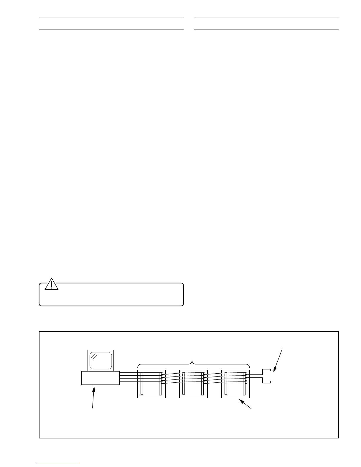
3 INSTALLATION ............................................................3
3.1 Serial Communication Adaptors
for Personal Computers ....................................3
3.1.1 Five-wire Configuration .......................3
3.1.2 Three-wire Configuration.....................3
4 ELECTRICAL CONNECTIONS ...................................3
4.1 Serial Connections ............................................3
4.1.1 Five-wire Cable....................................3
4.1.2 Three-wire Cable .................................3
5 SETTING UP ................................................................5
5.1 Termination Resistors........................................5
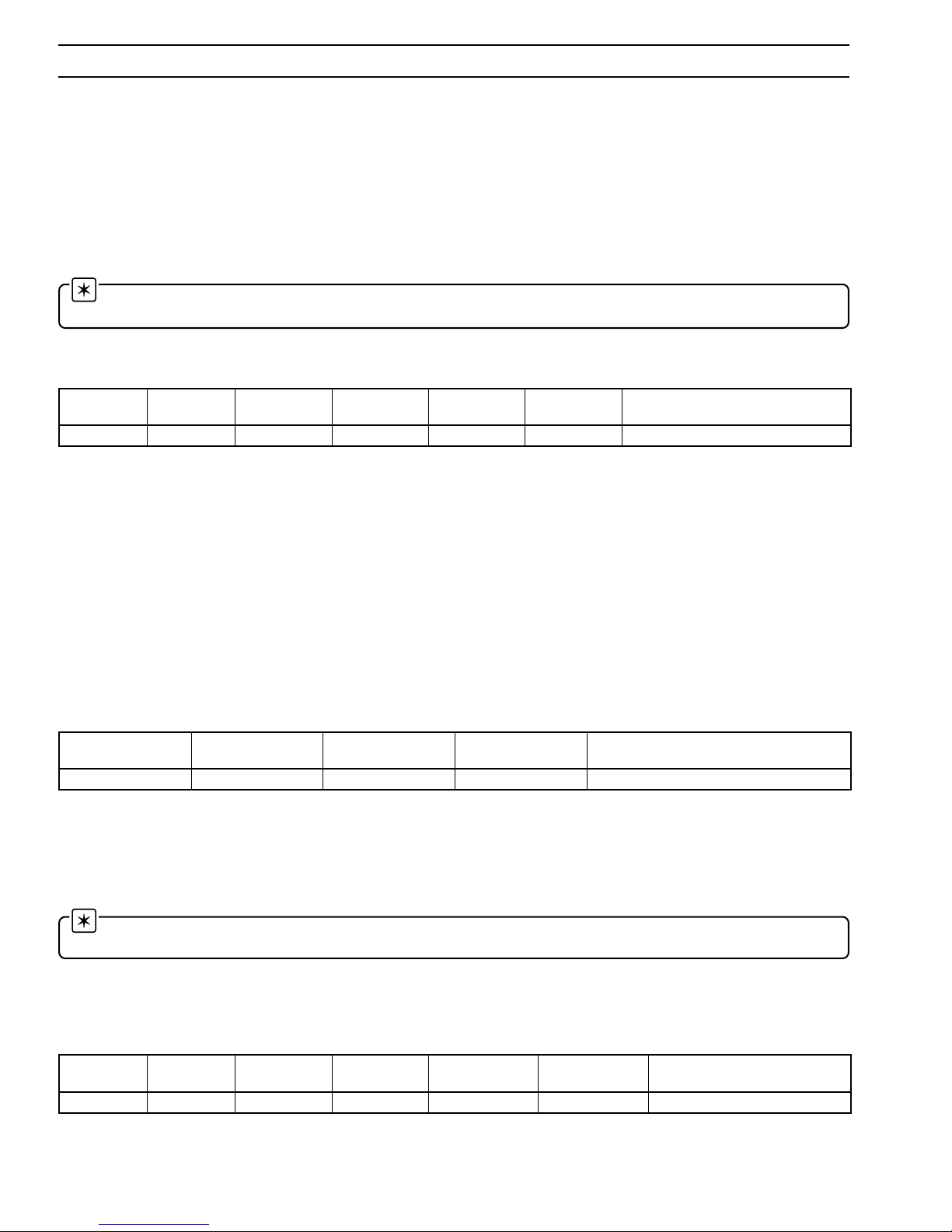
6 PROGRAMMING..........................................................6
6.1 Serial Interface Page.........................................6
7 MODBUS PROTOCOL ................................................7
7.1 Introduction to Modbus Protocol
(RTU only) .........................................................7
7.2 Modbus Function Codes ...................................7
8 MODBUS FUNCTIONS................................................8
8.1 Read Coil Status
– Function Code 01...........................................8
8.1.1 Read Coil Status Query.......................8
8.1.2 Read Coil Status Response ................8
8.2 Read Holding Register
– Function Code 03...........................................8
8.2.1 Read Holding Register Query .............8
8.2.2 Read Holding Register Response.......9
8.3 Force Single Coil
– Function Code 05...........................................9
8.3.1 Force Single Coil Query ......................9
8.3.2 Force Single Coil Response................9
8.4 Preset Single Register
– Function Code 06.........................................10
8.4.1 Preset Single Register Query............10
8.4.2 Preset Single Register Response .....10
8.5 Loopback Test
– Function Code 08......................................... 11
8.5.1 Loopback Test Query......................... 11
8.5.2 Loopback Test Response .................. 11
8.6 Preset Multiple Registers
– Function Code 16......................................... 11
8.6.1 Preset Multiple
Registers Query................................. 11
8.6.2 Preset Multiple
Registers Response .......................... 11
Section Page
9 EXCEPTION RESPONSES .......................................12
9.1 Examples.........................................................12
10 MODBUS COILS AND REGISTERS .........................12
10.1 Conductivity Transmitters
Models 4620/25...............................................12
10.1.1 Coils ...................................................12
10.1.2 Holding Registers ..............................13
10.2 Conductivity Transmitters Multi-electrode
Versions Models 4621/26................................14
10.2.1 Coils ...................................................14
10.2.2 Holding Registers ..............................14
10.3 Conductivity Transmitters to meet USP
Regulations Models 4623/28 ..........................15
10.3.1 Coils ...................................................15
10.3.2 Holding Registers ..............................15
10.4 pH Transmitters
Models 4630/35 and 4631/36 .........................16
10.4.1 Coils ...................................................16
10.4.2 Holding Registers ..............................17
10.5 Dissolved Oxygen Analyzers
Models 4640/45 and 4642/47 .........................18
10.5.1 Coils ...................................................18
10.5.2 Holding Registers ..............................18
10.6 Low Level Dissolved Oxygen Analyzers
Models 4641/46...............................................19
10.6.1 Coils ...................................................19
10.6.2 Holding Registers ..............................19
10.7 Turbidity Analyzers
Models 4670 and 4675....................................20
10.7.1 Coils ...................................................20
10.7.2 Holding Registers ..............................20
10.8 Biocide Cleaning Control (4691).....................21
10.8.1 Coils ...................................................21
10.8.2 Holding Registers ..............................21
11 OPERATION...............................................................22
12 SPECIFICATION ........................................................24
APPENDICES .....................................................................24
A1 Non-volatile Memory Limitations.....................24

2
1 INTRODUCTION 2 PREPARATION
This manual must be read in conjunction with the appropriate
Operating Instructions, depending on the instrument type:
• Models 4620, 4621, 4625 & 4626
Conductivity Transmitters – IM/4600–CON
• Models 4623 & 4628 Conductivity
Transmitters to meet USP 23 – IM/4600–USP
• Models 4630 & 4635
pH Monitors – IM/4630–PH
• Models 4640 & 4645
Dissolved Oxygen Monitors – IM/4600–DO
• Models 4670 & 4675
Turbidity Monitors – IM/4670
Forrepeatableand reliable serial communicationtotake place
between a master (host computer) and slaves (instruments) it
isessentialthatthetwoconditionsdetailedinthissectionaremet.
1.1 Electrical Connection
A standard method of electrical connection is used between
the master and the slaves, with defined voltage levels and
characteristics. The transmitter and receiver integrated
circuits within the 4600 meet the requirements of the EIA
(Electronic Industries Association, American) RS485 and
RS422 Serial Interface Standards.
The RS422/485 communication standard is used with the
following logic levels:
a) for logic '1' (MARK condition or IDLE state) the 'A'
terminal of the transmitter is negative (0V) with
respect to the 'B' terminal (+5V)
b) for logic '0' (SPACE condition or ACTIVE state) the 'A'
terminal of the transmitter is positive (+5V) with
respect to the 'B' terminal (0V).
Note. The 'A' terminal is Tx + or Rx + and the 'B'
terminal is Tx – or Rx –.
1.2 Protocol
A standard language or protocol must be used in both the
master and the slaves for messages (commands and data) to
be interpreted and acted upon. To achieve this second
condition, Modbus Protocol is utilized on the 4600 Series
Monitor using the Remote Terminal Unit (RTU) mode only.
Two methods of message error checking are used. Parity
checking is used, if selected, to detect transmission errors in
individual characters.
Parity is used for simple error checking.The parity bit is a one-
bitcodewhich is transmittedinaddition to theASCIIcharacter.
Itcandetectonlyoneerrorpercharacter, since two errors may
cancel out. Parity is calculated by finding the sum of logic '1's
in the character and either:
a) setting the parity bit to logic '1' if the sum is odd, or logic
'0' if the sum is even, when using even parity.
or
b) setting the parity bit to logic '0' if the sum is odd, or logic
'1' if the sum is even, when using odd parity.
Cyclic Redundancy Checking (CRC-16) is used to detect errors
in the Master messages and Slave responses. This therefore
detectserrors inthecompletemessage sentandalso thereplies.
Preparation is as given in the
Operating Instructions
– see Section 1, with additions as detailed in this section.
2.1 Company Standard Settings
Only those parameters detailed on the customer order are
programmed at the factory. If any parameters are unsuitable
for the application they can be reprogrammed –
see Section 7
of the Operating Instructions
. Serial data programming details
are given in Section 7 of this manual.
Standard parameter settings for the serial data programme
are as follows:
Instrument Identity 01
Parity none
Transmission Rate 9600 baud.

3
3 INSTALLATION 4 ELECTRICAL CONNECTIONS
Fig. 4.1 Schematic Diagram
Computer Terminal or
Host Computer
Chain of 4600 Transmitters
(Connected)
Last 4600
in Chain
Termination Resistor
(on 4600s receive input)
Observethelimitations outlinedinthe
OperatingInstructions
–
see Section 1. The maximum serial data transmission line
length for both RS422 and RS485 systems is 1200m.
3.1 Serial Communication
Adaptors for Personal Computers
An RS422/485 communications adaptor board is required for
serial links. It is strongly recommended that the card used has
galvanic isolation to protect the computer from lightning
damage and increase immunity from noise pick-up from
cables.
3.1.1 Five-wire Configuration
The following OPTO22 boards are recommended for use with
the 4600 serial instruments:
Part No. ComputerType
AC24 XT Bus IBM PC compatible
AC24 AT AT Bus IBM PC compatible
AC34 Microchannel IBM PC.
The following 'jumper' selections are required on OPTO22
boards (usually supplied as the default configuration):
RX & TX install line termination jumper
Install pull-up and pull-down jumpers
CTS & RTS disable jumper installed.
Select board address and interrupts as described in the
OPTO22 manual.
3.1.2 Three-wire Configuration
The adaptor card must have the provision for disabling the
transmitter after each message is transmitted, so that bus
contention does not occur. This is often implemented by the
useofthe RTSsignal to controlthetransmitterenable.Consult
the adaptor card manufacturer to determine suitability.
Caution. Install the pull-up/pull-down resistors
on either the RX or TX lines. The resistors must not be
connected on both pairs of lines.
All connections, apart from those for serial data
communication, are made as shown in Figs. 4.3 and 4.4 of the
Operating Instructions
– see Section 1.
4.1 Serial Connections – Figs. 4.1 and 4.2
Thetransmittersmust be connected inparallelas shown in the
schematic diagram – Fig. 4.1. The RS485 standard quotes
connection of maximum thirty two slaves (4600 Transmitters)
to any single driver (computer terminal or host computer); the
RS422 standard quotes connection of up to ten slaves.
However, these numbers can be increased if the driver's serial
port permits.
Make serial data connections and check the processor board
links as shown in Fig.4.2.The type of cable used is dependent
on the transmission speed and cable length:
4.1.1 Five-wire Cable
(refer also to Fig. 11.1)
Up to 6m (all speeds) – standard screened or twisted pair
cable.
Up to300m – twintwisted pairwithoverallfoilscreenandan
integral drain wire, e.g. Belden 9502 or equivalent
Up to 1200m – twin twisted pair with separate foil screens
and integral drain wires for each pair, e.g. Belden 9729 or
equivalent
4.1.2 Three-wire Cable (refer also to Fig. 11.2)
Up to 6m (all speeds) – standard screened or twisted pair
cable.
Up to 1200m – single twisted pair with overall foil screen
and integral drain wire, e.g. Belden 9501 or equivalent.

4
…4 ELECTRICAL CONNECTIONS
Serial
TBA TBB
Common (0V)
Rx+
Rx–
Tx+
Tx–
1
2
3
4
5
Channel 1 Channel 2 Power
Supply
Retrans. Relay 1
Relay 2
123
45
1 – No connection
2 – Rx+
3 – Rx–
4 – Tx+
5 – Tx–
6 – Common (0V)
6
123
45
1 – No connection
2 – No connection
3 – No connection
4 – Rx/Tx+
5 – Rx/Tx–
6 – Common (0V)
6Rx/Tx–
1
2
3
4
5
A – Five-wire Connections
B – Three-wire Connections
3-wire 5-wire
IC22 IC23
IC25
IC24
12
11 12
Note. For 3-wire applications IC25 must be removed
and the 3-wire link positioned as shown.
✶
Processor Board
C – Three- and Five-wire Links
✶
Common (0V)
Rx/Tx+
12
11 12
12
11 12
…4.1 Serial Connections
Fig. 4.2 Serial Connections

5
5 SETTING UP
Termination
Resistors
IN
Termination
Resistors
OUT
IC22 IC23
IC25
IC24
12
11 12
Processor Board
12
11 12
12
11 12
For all aspects other than serial data transmission the
transmitter is set up as shown in the
Operating Instructions
–seeSection 1.Unlessotherwiserequested, theinstrumentis
despatched with a transmission rate of 9600 baud and
transmission line termination resistors linked-out. If the
resistors are to be linked-in (see Fig. 5.1) carry out the
following section.
5.1 Termination Resistors – Fig. 5.1
For long transmission lines, termination resistors are required
on the last 4600 Transmitter in the chain and at the host
computer/computer terminal. Under normal operating
conditions the resistors are required at the last 4600 receive
inputs only – see Fig. 4.1. The transmitter's resistors are
selected using plug-in links – see Fig. 5.1.
Switch off the supply and gain access to the processor board
(Section 4 in the Operating Instructions).
Set the termination
resistor links as shown in Fig. 5.1.
Fig. 5.1 Termination Resistor Links

6
6 PROGRAMMING
Inst. Identity
1
SERIAL INTERFACE
–––––
Baud Rate 9600
–––––
Parity ODD
–––––
SET UP OUTPUTS
–––––
ELECTRICAL CAL
–––––
The general programming procedure is as detailed in the
Operating Instructions
but with an additional Serial Interface page
between the Set Up Outputs and Electrical Cal pages.
6.1 Serial Interface Page Page Header – Serial Interface
Transmission Rate
Select the retransmission rate required (1200 slowest, 9600 fastest).
Transmitter Identification
Assign the transmitter an identification number (1 to 99) – see Section 4.1.The
identification number allows more than one transmitter to be accessed via the
communication channel.
Parity
Select the appropriate parity to match the computer terminal or host computer.
Return to the top of the Serial Interface Page or advance to the next page.
Inst. Identity
1
SERIAL INTERFACE
–––––
Baud Rate 1 00
–––––
400
4800
9600
Parity EVEN
–––––
ODD
NONE
Fig. 6.1 Location of Serial Data Interface Page

7
7 MODBUS PROTOCOL
subdoM edoCnoitcnuF emaNegasseMsubdoM noitinifeDsubdoM0064
10sutatSlioCdaeR 0064ehT.tniopcificepsamorfstniop)naeloob(etercsidevitucesnoc61otpudaeR roftseuqeryna*sKANdnaataddenifedniatnoctonodhcihwstnioprofsorezsnruter .001tahtretaergsrebmuntniop
30retsigeRgnidloHdaeR sorezsnruter0064ehT.retsigergnitratscificepsamorfsretsigerevitucesnoc8otpU retsigerroftseuqerynasKANdnaataddenifedniatnoctonodhcihwsretsigermorf .001nahtretaergsrebmun
50lioCelgniSecroF yltnerructonsitniopehtfisihtsKAN0064ehT.tniop)naeloob(etercsidenoetirW .elbaetirw
60retsigeRelgniSteserP noitcnufsihT.elbaetirwyltnerructonsiretsigerehtfisKAN0064ehT.retsigerenoetirW .esabatadehtniegarotserofebretsigerehtotstimilgnitsixeynaseilppaoslaedoc
80tseTcitsongaiDkcabpooL .detroppussi'yreuQfonruteR'ylno,egassemehtohcE
61sretsigeRelpitluMteserP fisKAN0064ehT.retsigergnitratsdeificepsamorfsretsigerevitucesnoc8otpuetirW erahcihwsetirwehtllatuoseirracllitstub,elbaetirwyltnerructonerasretsigerehtfoyna .esabatadehtniegarotserofebeulavehtotstimilelbacilppayltnerrucynagniylppa,dilav
tnemegdelwonkcAevitageN=KAN*
7.1 Introduction to Modbus Protocol (RTU only)
Modbus communication is based on a master and a slave arrangement.The master sends a message to one slave at a time and
waits for a reply.
The slave cannot accept a new message until the existing message is processed and a reply sent to the master (maximum
response time 250 milliseconds).The slave monitors the elapsed time between receipt of characters.If the elapsed time without
a new character is31/2character times, the slave assumes the next character received is the start of a new message.
To allow the master to differentiate between more than one slave in a system, each slave is given a unique identity address
(between 1 and 99).
A broadcast address (address zero) can be used to access all slave devices with one command. This is limited to write
messages only and there is no slave acknowledgment.
Note. Modbus RTU requires 1 start bit, 8 data bits, 1 parity bit (optional) and 1 or 2 stop bits. The 4600 uses only
1 stop bit.
7.2 Modbus Function Codes –Table 7.1
The function code field instructs the addressed slaves which function to perform.
Table 7.1 Modbus Function Codes

8
8 MODBUS FUNCTIONS
This section shows typical examples of Modbus function codes 01, 03, 05, 06, 08 and 16.
8.1 Read Coil Status –Function Code 01
8.1.1 Read Coil Status Query
This function allows the user to obtain the ON/OFF status of logic coils used to control discrete outputs from the addressed slave
only. Broadcast mode is not supported with this function code. In addition to the slave address and function fields, the message
requires that the information field contain the initial coil offset address to be read (starting address) and the number of locations
to be interrogated must obtain status data.
Note. The coil offset address is the coil number minus one, e.g.to start at coil 31 the data start value must be set to 30
(1EH).
Example – a read coil status request to read 7 coils from slave (01) starting at coil 11 (Alarm 1 Relay State) is shown below.
8.1.2 Read Coil Status Response
The data is packed one bit for each coil (1 = ON, 0 = OFF).The response includes the slave address, function code, quantity of
data characters, the data characters and error checking.The low order bit of the first character contains the first addressed coil
and the remainder follow.For coil quantities that are not even multiples of eight, the last characters are filled in with zeros at high
order end.
Example – the response to the read coil status query shows the following:
Relay alarm state 1 OFF
Relay alarm state 2 OFF
No coil at this address
Channel 1 input error
Channel 2 input error
No coil at this address
NV check sum error
8.2 Read Holding Register –Function Code 03
8.2.1 Read Holding Register Query
The Read holding registers allow the user to obtain the binary contents of holding registers in the addressed slave.
Note. The data start register must contain the offset address of the first register to be accessed, e.g.to start at register
11 the data start register must contain 10 (0AH).
Broadcast mode is not allowed.
Example – a read holding register request to read 6 holding registers from slave (01) starting at holding address 121 (alarm trip
A1) is shown below.
sserddAnoitcnuF tratSlioC hgiHtesffO tratSlioC woLtesffO forebmuN hgiHslioC forebmuN woLslioC )61-CRC(dleiFkcehCrorrE
101000A00070D5AC
sserddAnoitcnuF tratSretsigeR hgiHtesffO tratSretsigeR woLtesffO forebmuNataD hgiHsretsigeR forebmuNataD woLsretsigeR )61-CRC(dleiFkcehCrorrE
103000A000401CAC
sserddAnoitcnuFtnuoCetyB sutatSlioCataD 81ot11 )61-CRC(dleiFkcehCrorrE
101010300D94

9
8 MODBUS FUNCTIONS…
8.2.2 Read Holding Register Response
The addressed slave responds with its address and function code, followed by the information field.The information field contains
1 byte describing the quantity of data bytes to be returned.The contents of each register requested (DATA) is two bytes, the first
byte includes the high order bits and the second the low order bits.
Example – the response to the read holding register query shows the following:
Measured conductivity – 60.0µS/cm (Range: 0 to 100µS/cm)
Conductivity set point 1 – 80.0µS/cm
Conductivity set point 2 – 20.0µS/cm
Measured temperature – 49°C (Range: –10 to 110°C)
8.3 Force Single Coil –Function Code 05
8.3.1 Force Single Coil Query
This message forces a single coil either ON or OFF.The data value 65,280 (FF00 HEX) sets the coil ON and the value zero turns
it OFF. All other values are illegal and do not affect the coil.
Note. To write to a coil the coil offset address must be used, e.g. to write to coil 50, the coil address 49(31H) is
transmitted.
The use of slave address zero (broadcast mode) forces all attached slaves to modify the desired coil.
Example – a force single coil request to switch ON coil address 50 (NV Memory Save) in slave 01 is shown below.
8.3.2 Force Single Coil Response
The response is confirmation of the query after the coil state has been altered.
Example:
sserddAnoitcnuFtnuoCetyB gnidloH 11retsigeR gnidloH 21retsigeR gnidloH 31retsigeR gnidloH 41retsigeR dleiFkcehCrorrE )61-CRC(
hgiHwoLhgiHwoLhgiHwoLhgiHwoL
1030809099C0CC3033701EC09F
sserddAnoitcnuF tesffOlioC hgiH tesffOlioC woL eulaVataD hgiH eulaVataD woL )61-CRC(dleiFkcehCrorrE
10500013FF00DD5F
sserddAnoitcnuF tesffOlioC hgiH tesffOlioC woL eulaVataD hgiH eulaVataD woL )61-CRC(dleiFkcehCrorrE
10500013FF00DD5F

10
…8 MODBUS FUNCTIONS
8.4 Preset Single Register –Function Code 06
8.4.1 Preset Single Register Query
The preset single register allows the user to modify the contents of a holding register.
Note. Function codes 5, 6 and 16 are the only messages that are recognized as valid for broadcast.
Example – a preset single register request to write the value 60.0 to holding register address 12 (alarm trip A1) in slave 01 is
shown below.
Since all register values for measured variables and alarm set points (scaled parameters) are ranged to 12 bits (for RTU), then
to calculate the Data Value High and Data Value Low for a setpoint of 60.0 the following method is used:
Instrument Range = 0 to 100.0
therefore
60.0 x 4095
100.0 = 2457
10
converted to hexadecimal 245710 = 099916
therefore Data Value High = 09
Data Value Low = 99
Note. To write to a register, the register's offset address must be used, e.g. to write to register 12, the offset address
11(0B) is transmitted.
8.4.2 Preset Single Register Response
The normal response to a preset single register request is to retransmit the query message after the register has been altered.
Example:
sserddAnoitcnuF retsigeR hgiHtesffO retsigeR woLtesffO hgiHeulaVataDwoLeulaVataD)61-CRC(dleiFkcehCrorrE
106000B09099E323
sserddAnoitcnuF retsigeR hgiHtesffO retsigeR woLtesffO hgiHeulaVataDwoLeulaVataD)61-CRC(dleiFkcehCrorrE
106000B09099E323

11
8 MODBUS FUNCTIONS
8.5 Loopback Test –Function Code 08
8.5.1 Loopback Test Query
The purpose of the loopback test is to test the Modbus system, it does not affect the content of the controller.Variations in the
response may indicate faults in the Modbus system.The information field contains 2 bytes for the designation of the diagnostic
code followed by 2 bytes to designate the action to be taken.
Example:
8.5.2 Loopback Test Response
The response always echoes the query, only diagnostic code 0 (bytes 3 and 4) can be used.
Example:
8.6 Preset Multiple Registers –Function Code 16
8.6.1 Preset Multiple Registers Query
Holding registers existing within the controller can have their contents changed by this message. When used with slave address
zero (Broadcast mode) all slave controllers load the selected registers with the contents specified.
Note. To write to multiple registers, the initial register offset address must be used, e.g.to write to register 02 onwards,
the offset address 01 is transmitted.
Example–a presetmultiple registersrequest towritethevalue90.0totheregisteraddress (AlarmSet Point1) andthevalue30.0
to the register address (Alarm Set Point 2) in slave 01 is shown below.
8.6.2 Preset Multiple Registers Response
The response confirms slave identification, function code, starting register address and quantity only.
Example:
sserddAnoitcnuF retsigeR hgiHtesffO retsigeR woLtesffO hgiHeulaVataDwoLeulaVataD)61-CRC(dleiFkcehCrorrE
108000B09099753F
sserddAnoitcnuF citsongaiDataD hgiHedoC citsongaiDataD woLedoC *ataD*ataD)61-CRC(dleiFkcehCrorrE
108000B09099753F
.edomcitsongaidrofsdleifnoitamrofniehtebotderedisnoceraesehT*
sserddAnoitcnuF tratSretsigeR tesffO forebmuN sretsigeR etyB tnuoC
retsigeRgnidloH 20 retsigeRgnidloH 30 dleiFkcehCrorrE )61-CRC(
hgiHwoLhgiHwoLhgiHwoL
100100B0002040E05640CC2AE7
sserddAnoitcnuF tratSretsigeR hgiHtesffO tratSretsigeR woLtesffO sretsigeRforebmuN)61-CRC(dleiFkcehCrorrE
100100B0002003A0

12
10 MODBUS COILS AND REGISTERS
rebmuNtupnIetirW/daeRnoitpircseD yrtnE/esnopseR
110 210 R
RetatSyaleR1mralA etatSyaleR2mralA elbasiD=0 elbanE=1
410 510 710
R
R
R
rorrEtupnI1lennahC rorrEtupnI2lennahC rorrEmuSkcehCVN
.K.O=0 rorrE=1
050W/Ryromemelitalov-nonehtotsetirwelbanEelbasiD=0 elbanE=1
9 EXCEPTION RESPONSES
noitpecxE esnopseR edoC emaNesnopseRnoitpecxE noitinifeDesnopseRnoitpecxE
10noitcnuFlagellI .tnemurtsniehtrofnoitcaelbawollanatonsideviecernoitcnufegassemehT
20sserddAataDlagellI .tnemurtsniehtrofsserddaelbawollanatonsidleifatadehtniecnerefersserddaehT
30eulaVataDlagellI .noitacolevalsdesserddaehtnielbawollatonsidleifatadehtnidecnerefereulavehT
70tnemegdelwonkcAevitageN .demrofrepebtonnacdetseuqertsujnoitcnufehT
80rorrEytiraPyromeM .deviecersretcarahcehtfoeromroenonirorrenasetacidnikcehcytiraP
The exception response codes sent by the slave are shown in Table 9.1.When a slave detects one of these errors, it sends a
response message to the master consisting of slave address, function code, error code and error check fields.
9.1 Examples
A read register request to read holding register address 251 of slave 01 (undefined address for slave, beyond address limit) is
shown below.
The response is an exception response sighting 'illegal data address'.To indicate that the response is a notification of an error,
the most significant bit of the function code is set to 1.
Table 9.1 Exception Response Data
sserddAevalSnoitcnuFtesffOtratSretsigeRsretsigeRforebmuN)61-CRC(dleiFkcehCrorrE
hgiHwoLhgiHwoL
103000AF00605E9F
sserddAevalSnoitcnuFedoCnoitpecxE)61-CRC(dleiFkcehCrorrE
1038200C1F
10.1 Conductivity Transmitters Models 4620/25
10.1.1 Coils

13
10 MODBUS COILS AND REGISTERS…
tupnI rebmuN etirW/daeRnoitpircseD delacS retemaraP yrtnE/esnopseR
110 210 310
R
W/R W/R
ytivitcudnoCderusaeM 1AtnioPteSytivitcudnoC 2AtnioPteSytivitcudnoC
✓
✓
✓egnaryalpsiddemmargorpnihtiW
410R erutarepmeTderusaeM ✓011ot01–°032ot41(C °)F
610 710 910 020
W/R W/R W/R W/R
1AtnioPteSsmhogeM 2AtnioPteSsmhogeM 1AtnioPteSerutarepmeT 2AtnioPteSerutarepmeT
✓
✓
✓
✓
120R stinUytivitcudnoCmc/snemeisorcim=0 m/snemeisorcim=1 mc/snemeisillim=2 m/snemeisillim=3 .S.D.T=4 ytinilaS=5
220R tnatsnoClleC00.1ot50.0
320R napSytivitcudnoCehtotrefeR )NOC–0064/MI(snoitcurtsnIgnitarepO mumixamrof
dedeecxeebtontsumhcihwsegnarmuminimdna
420R oreZytivitcudnoC)5ot0MUrof(oreZ
520R noitisoPtnioPlamiceDxxxxx=0 x.xxxx=1 xx.xxx=2 xxx.xx=3 ehtotrefeR )NOC–0064/MI(snoitcurtsnIgnitarepO mumixamrof
dedeecxeebtontsumhcihwsegnarmuminimdna
720R stinUerutarepmeT=0°C
=1 °F
130R noitasnepmoCerutarepmeToN=0 seY=1
230R tneiciffeoC.pmeT.loS /%3ot0(030.0ot000.0 °)C
430R erutarepmeTecnerefeR02=0 °86roC °F
52=1 °77roC °F
730R rotcaFsdiloSdevlossiD
140 240 R
RnoitcA1AmralA noitcA2AmralA woL=0 hgiH=1
440R epyTnoissimsnarteRAm01ot0=0 Am02ot0=1 Am02ot4=2
740 840 R
RepyT1AmralA epyT2AmralA ffO=0 dnoC=1 pmeT=2 liaF=3
050R evruCnoissimsnarteRraeniL=0 raeniL-iB=1 cimhtiragoLedaceD-2=2 cimhtiragoLedaceD-3=3 cilobrepyHedaceD-2=4 cimhtiragoL-imeSBBA=5
150R napSnoissimsnarteR
250R oreZnoissimsnarteR
…10.1 Conductivity Transmitters Models 4620/25
10.1.2 Holding Registers

14
tupnI rebmuN etirW/daeRnoitpircseD delacS retemaraP yrtnE/esnopseR
110 210 310
R
W/R W/R
eulaVderusaeM 1AtnioPteS 2AtnioPteS
✓
✓
✓egnaryalpsiddemmargorpnihtiW
510R erutarepmeTderusaeM ✓011ot01–°032ot41(C °)F
120R erusaemfostinUmc/snemeisorcim=0 m/snemeisorcim=1 mc/snemeisillim=2 m/snemeisillim=3 .S.D.T=4 ytinilaS=5
320R eulaVnapSehtotrefeR )CEM–0064/MI(snoitcurtsnIgnitarepO mumixamrof
dedeecxeebtontsumhcihwsegnarmuminimdna
720R stinUerutarepmeT=0°C
=1 °F
130R *noitasnepmoCerutarepmeToN=0 seY=1
230R *tneiciffeoCerutarepmeToN=0 seY=1
430R *erutarepmeTecnerefeR02=0 °86roC °F
52=1 °77roC °F
140 240 R
RnoitcA1AmralA noitcA2AmralA woL=0 hgiH=1
440R epyTnoissimsnarteRAm01ot0=0 Am02ot0=1 Am02ot4=2
740 840 R
RepyT1AmralA epyT2AmralA ffO=0 dnoC=1 pmeT=2 liaF=3
050R evruCnoissimsnarteRraeniL=0 raeniL-iB=1
150R napSnoissimsnarteR
250R oreZnoissimsnarteR
.stinurehtollanotuodeirracyllacitamotuasinoitasnepmocerutarepmeT.mc/SmtoneraerusaemfostinuehtfierongI*
rebmuNtupnIetirW/daeRnoitpircseDyrtnE/esnopseR
110 210 R
RetatSyaleR1mralA etatSyaleR2mralA elbasiD=0 elbanE=1
410 510 710 020
R
R
R
R
rorrEtupnI1lennahC rorrEtupnI2lennahC rorrEmuSkcehCVN rorrEgniluoFlleC
.K.O=0 rorrE=1
120R erutarepmeTrednU/revO.K.O=0 rorrE=1
050W/R elitalov-nonehtotsetirwelbanE yromem elbasiD=0 elbanE=1
…10 MODBUS COILS AND REGISTERS
10.2 Conductivity Transmitters Multi-electrode Versions Models 4621/26
10.2.1 Coils
10.2.2 Holding Registers

15
10 MODBUS COILS AND REGISTERS…
tupnI rebmuN etirW/daeRnoitpircseD delacS retemaraP yrtnE/esnopseR
110 210 310
R
W/R W/R
ytivitcudnoCderusaeM 1AtnioPteS 2AtnioPteS
✓
✓
✓egnaryalpsiddemmargorpnihtiW
510R erutarepmeTderusaeM ✓011ot01–°032ot41(C °)F
910R )pmeT(tnioPteS1mralA ✓
020R )pmeT(tnioPteS2mralA ✓
220R tnatsnoClleC00.1ot50.0
320R eulaVnapSehtotrefeR )PSU–0064/MI(snoitcurtsnIgnitarepO mumixamrof
dedeecxeebtontsumhcihwsegnarmuminimdna
720R stinUerutarepmeT=0°C
=1 °F
140 240 R
RnoitcA1AmralA noitcA2AmralA woL=0 hgiH=1
440R epyTnoissimsnarteRAm01ot0=0 Am02ot0=1 Am02ot4=2
740 840 R
RepyT1AmralA epyT2AmralA ffO=0 dnoC=1 pmeT=2 liaF=3 )ylnoepyT2AmralA(PSU=4
050R evruCnoissimsnarteRraeniL=0 raeniL-iB=1
150R napSnoissimsnarteR
250R oreZnoissimsnarteR
rebmuNtupnIetirW/daeRnoitpircseDyrtnE/esnopseR
110 210 R
RetatSyaleR1mralA etatSyaleR2mralA elbasiD=0 elbanE=1
410 510 710
R
R
R
rorrEtupnI1lennahC rorrEtupnI2lennahC rorrEmuSkcehCVN
.K.O=0 rorrE=1
050W/R elitalov-nonehtotsetirwelbanE yromem elbasiD=0 elbanE=1
10.3 Conductivity Transmitters to meet USP Regulations Models 4623/28
10.3.1 Coils
10.3.2 Holding Registers

16
…10 MODBUS COILS AND REGISTERS
rebmuNtupnIetirW/daeRnoitpircseDyrtnE/esnopseR
110 210 R
RetatSyaleR1mralA etatSyaleR2mralA elbasiD=0 elbanE=1
410 510 710
R
R
R
rorrEtupnI1lennahC rorrEtupnI2lennahC rorrEmuSkcehCVN
.K.O=0 rorrE=1
810R *ssergorPnihsaWoN=0 seY=1
910R dleHstuptuOdleHtoN=0 dleH=1
020R ssergorPninoitarbilaCssergorPnI=0 ssergorPnitoN=1
050W/R elitalov-nonehtotsetirwelbanE yromem elbasiD=0 elbanE=1
.ylno6364dna1364sledoM*
10.4 pH Transmitters Models 4630/35 and 4631/36
10.4.1 Coils

17
tupnI rebmuN etirW/daeRnoitpircseD delacS retemaraP yrtnE/esnopseR
110 210 310
R
W/R W/R
eulaVHpderusaeM *)1=epyT1A(1AtnioPteSHp †)1=epyT2A(2AtnioPteSHp
✓
✓
✓egnaryalpsiddemmargorpnihtiW
410R erutarepmeTderusaeM ✓011ot01–°032ot41(C °)F
510R erutarepmeTteserP ✓011ot01–°032ot41(C °)F
710R eulaVepolSHpehtotrefeR )Hp–0064/MI(snoitcurtsnIgnitarepO
810 910 020 120 220 320
R
W/R W/RR
W/R W/R
eulaVkcehCHp 1AtnioPteSerutarepmeT 2AtnioPteSerutarepmeT eulaVstlovilliMderusaeM *)1=epyT1A(1AtnioPteSVm †)1=epyT2A(2AtnioPteSVm
✓
✓
✓
✓
✓
egnaryalpsiddemmargorpnihtiW
130R epyTtupnI tnioplamicedon,)PRO(xodeR=0 stnioplamiced2,ssalGHp=1 stnioplamiced2,ynomitnAHp=2
330R napSHpHp41
430R oreZHpHp0
630R napSVmVm0001
730R oreZVmVm0001–
930R stinUerutarepmeT=0°C
=1 °F
140R noitasnepmoCerutarepmeT oN=0 seY=1
240R noitasnepmoC.pmeTelpmaS )edortcelEynomitnAehthtiwdesutoN(oN=0 seY=1
340R tneiciffeoC.pmeTelpmaS stnioplamiced3,edortcelEynomitnAehthtiwdesutoN
540 640 R
RnoitcA1AmralA noitcA2AmralA woL=0 hgiH=1
740 840 R
RepyT1AmralA epyT2AmralA ffO=0ffO=0 Hp=1 RO xodeR=1 )ylnoepyT2AmralA(hsaWretaW=2pmeT=2 liaF=3 )ylnoepyT2AmralA(hsaWretaW=4
940R epyTnoissimsnarteRAm01ot0=0 Am02ot0=1 Am02ot4=2
150R napSnoissimsnarteR
250R oreZnoissimsnarteR
.0=tnioPteS1AmralAnehT,liaFroffOottessiepyT1AmralAfI* .0=tnioPteS2AmralAnehT,hsaWretaWroliaF,ffOottessiepyT2AmralAfI†
10 MODBUS COILS AND REGISTERS…
…10.4 pH Transmitters Models 4630/35 and 4631/36
10.4.2 Holding Registers

18
…10 MODBUS COILS AND REGISTERS
rebmuNtupnIetirW/daeRnoitpircseDyrtnE/esnopseR
110 210 R
RetatSyaleR1mralA etatSyaleR2mralA elbasiD=0 elbanE=1
410 510 710
R
R
R
rorrEtupnI1lennahC rorrEtupnI2lennahC rorrEmuSkcehCVN
.K.O=0 rorrE=1
810R *ssergorPnihsaWoN=0 seY=1
910R dleHstuptuOdleHtoN=0 dleH=1
020R ssergorPninoitarbilaCssergorPnI=0 ssergorPnitoN=1
050W/Relitalov-nonehtotsetirwelbanE yromem elbasiD=0 elbanE=1
.ylno7464dna2464sledoM*
tupnI rebmuN etirW/daeRnoitpircseD delacS retemaraP yrtnE/esnopseR
110 210 310
R
W/R W/R
negyxOdevlossiDderusaeM 1AtnioPteSnegyxOdevlossiD 2AtnioPteSnegyxOdevlossiD
✓
✓
✓egnaryalpsiddemmargorpnihtiW
410R erutarepmeTderusaeM ✓04ot0 °401ot23(C °)F
120R epyTtupnI stnioplamiced2,mpp=0 tnioplamiced1,taS%=1
320R napSnegyxOdevlossiD taS%0.002ot0.03rompp00.02ot00.3
420R oreZnegyxOdevlossiD taS%0.0rompp00.0
620R stinUerutarepmeT=0°C
=1 °F
820R noitcerroCytinilaS )taS%htiwdesuton(oN=0 seY=1
920R )tpp(ytinilaS )stnioplamicedon(ytinilaS taS%htiwdesutonsicinomenmsihT
330 430 R
RnoitcA1AmralA noitcA2AmralA AE=0 BE=1
630R epyTnoissimsnarteRAm01ot0=0 Am02ot0=1 Am02ot4=2
10.5 Dissolved Oxygen Analyzers Models 4640/45 and 4642/47
10.5.1 Coils
10.5.2 Holding Registers
This manual suits for next models
1
Table of contents
Other ABB Measuring Instrument manuals

ABB
ABB LGR-ICOS GLA531 Series User manual

ABB
ABB 2155 User manual

ABB
ABB 10D1475 User manual

ABB
ABB CoriolisMaster FCH400 Series User manual

ABB
ABB NGC8206 User manual

ABB
ABB XSeriesG4 User manual

ABB
ABB Relion RES670 User manual

ABB
ABB C1300 User manual

ABB
ABB SwirlMaster FSS430 Training manual

ABB
ABB Sensi+ User manual