FlashBake OVEN - GENERAL
3
GENERAL
INTRODUCTION
General
The FlashBake®oven is a versatile oven that
employs a revolutionary high quality, high speed
cooking technology. Thebaking process is so fast that
food retains its natural juices. Bread products brown
and become crisp while vegetables retain their color
and texture. The texture, appearance and quality of
food cooked in this oven is superior to that provided
by any other method of cooking.
In conventional ovens, the cooking process occurs by
transferring heat energy from the air inside the oven
into the food. Hot surfaces inside the oven also
transfer heat directly into the food by conduction. In
convection ovens, the air-to-food heat transfer is
enhanced by the uniform circulation of the heated air
around the food. Forced air ovens blow the heated air
directly onto the food, providing marginal increases in
cooking speeds.
FlashBakeovensusevisibleandinfraredlight energy
to cook by radiative heat transfer. The infrared energy
browns the surface of the food, while the visible light
energy penetrates and heats it internally. Using the
proper combination of visible and infrared light
energy, the FlashBake oven provides efficient, high-
speed baking and high-quality food.
• Use metal pans (thin wall pans will warp),
Corning Vision Ware®or foil.
• Do not use paper (it will burn), Pyrex®dishes or
plastic.
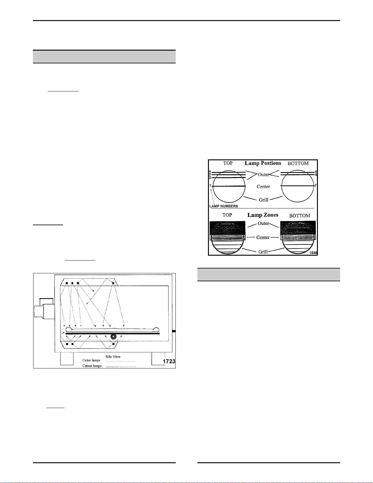
Zone Power Levels
The lamps are positioned sothat the center lamps are
above and below the center of the grill. The outer
lamps are located above and below the rear of the
grill. There is only one top center lamp and one
bottom center lamp. The top outer has three lamps
and the bottom outer has two lamps.
Changing the top outer and bottom outer power levels
will have a greater effect on cooking times and
browning than changing the center power levels. This
is because outer intensities contain 70% of the
cooking energy while the center intensities only
contain 30% of the cooking energy.
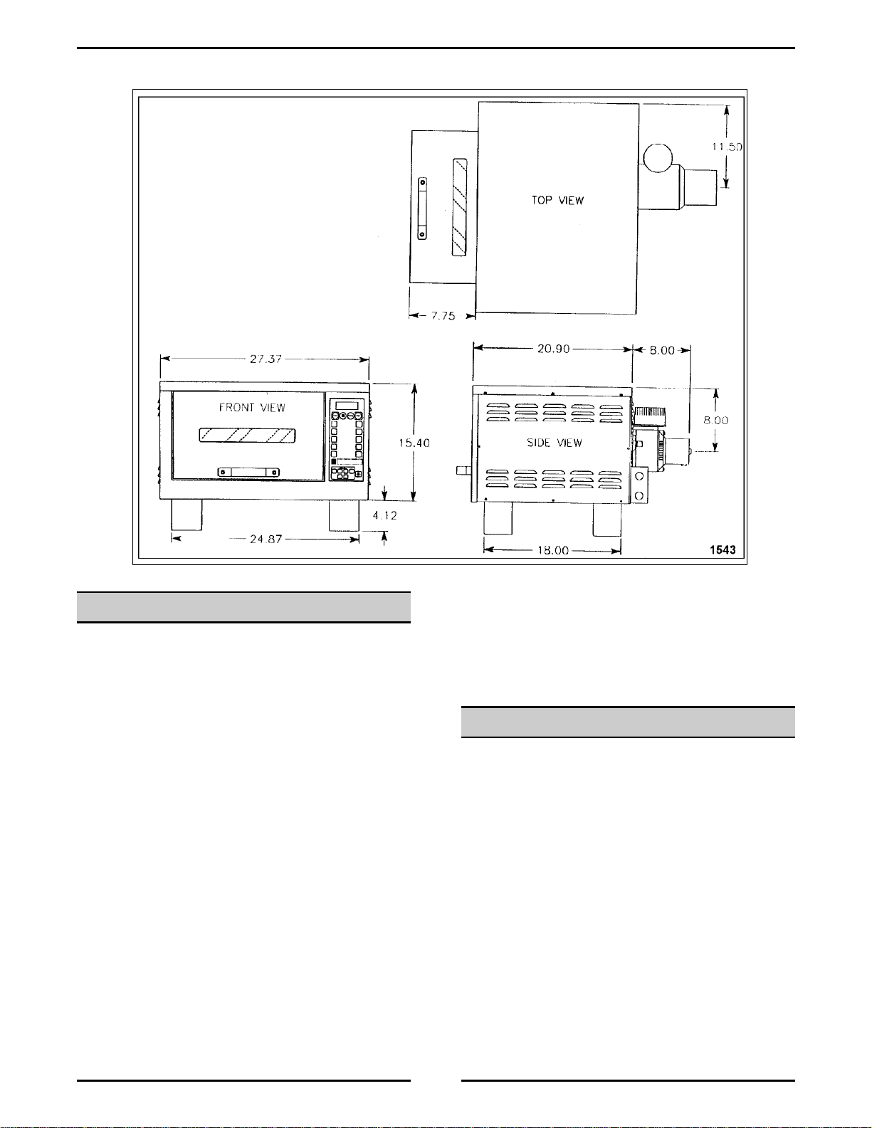
SPECIFICATIONS
General
• If the inlet air is obstructed or heated the oven
will not operate properly.
• Install the HFB12 oven on a level counter top or
other stable surface of sufficient strength to
safely support the oven.
• Position the oven at an appropriate height to
allow safe handling of hot food and convenient
access to the oven controls.
• Position the ovenso that the open door does not
extend into areas that may result in accidental
contact with hot oven parts.
• Theoven can be ordered with a 6' power cord for
receptacle installation. If this is the case assure
that the unit cord can be plugged into the outlet
without strain on the cord or plug.