VWR FSR-1404 User manual

Part number 20057, Rev 0
1
FLAMMABLE STORAGE REFRIGERATORS, FREEZERS, & DUAL-TEMP UNITS
MODELS FSR-1404, FSR-1704, FSR-2004, FSR-3004,
FSF-1420, FSF-1720, FSF-2020, FSF-3020, FS-RFC-30
(with options, “-DTD” Digital Temp Display, “-DA” CONTROL CENTER
Temp Alarm and/or “-CR” Chart Recorder)
OWNER’S INSTRUCTIONS
This manual describes how to operate and care for your appliance to get the best, most efficient, performance.
READ THIS BOOK!
Note to Customer:
This merchandise was carefully packed and thoroughly inspected before leaving our plant. Responsibility for its
safe delivery was assumed by the carrier upon acceptance of the shipment. As directed on the side of your
packing carton, claims for loss or damage sustained in transit must be made on the carrier as follows:
A.) Visible Loss, Damage, Shortage External Evidence of Loss or Damage: This type of damage must be noted on
the freight bill and acknowledged by the carrier’s agent (driver) at time of delivery. Make sure you get a signed
copy. Send a written request for an inspection to the carrier.
B.) Concealed Damage: This type of damage may not be discovered until the unit is being unpacked. When
concealed damage is discovered, stop unpacking immediately and contact the carrier immediately to report
the claim and request an inspection. This should be done as soon as possible and, in any case, must be done
within 15 days or receiving the merchandise. If at all possible, do not move the item and save all packaging
material for carrier’s inspection.
C.) FAILURE TO FOLLOW THESE INSTRUCTIONS MAY RESULT IN THE CARRIER REFUSING TO HONOR YOUR
COMPANY’S CLAIM. UNDER NO CIRCUMSTANCES SHOULD THE MERCHANDISE BE RETURNED TO THE
MANUFACTURER. NO RETURNS WILL BE ACCEPTED WITHOUT PRIOR AUTHORIZATION.
Horizon Scientific
125 Varnfield Drive
Summerville, SC 29483
Phone: 800-648-4041
Fax: 843-821-8051
Warranty:
Two-Year Parts and Labor
5 Years Compressor Parts
Revision Date
07/30/2013

Part number 20057, Rev 0
2
TABLE OF CONTENTS
RECEIVING ............................................................................................................. 4
INSTALLATION........................................................................................................ 5
REFRIGERATOR AND FREEZER OPERATION ............................................................ 7
DIGITAL TEMP DISPLAY (“-DTD” MODEL)............................................................... 8
CONTROL CENTER - TEMPERATURE MONITOR SYSTEM (“-DA” MODEL)................ 9
CHART RECORDER OPERATION (“-CR” MODEL) ................................................... 15
QUICK TROUBLESHOOTING GUIDE ...................................................................... 18
MAINTENANCE AND CLEANING ........................................................................... 20
HORIZON SCIENTIFIC, INC. PRODUCT WARRANTY ............................................... 22
BEFORE CALLING THE MANUFACTURER’S TECHNICAL SUPPORT DEPARTMENT,
please have the unit’s model and serial number ready as well as the problem
description. The model and serial number is located on the serial tag which can
be found on the interior left upper wall of the unit.
For convenience, you may want to record the following information here for easy
access in the future.
Model number: __________________________________
Serial number: __________________________________
Date of delivery: _________________________________

Part number 20057, Rev 0
3

Part number 20057, Rev 0
4
RECEIVING
Your unit was built, packaged, and inspected with extreme care. We shipped it to you using carriers we
trust with a proven track record of careful handling, good customer service, and on time delivery.
Unfortunately, regardless of all of these efforts sometimes accidents happen and occasionally those
accidents result in shipping damage. When the carrier picked up the merchandise from us, they
assumed responsibility for its condition en route to you. Thus, any claims for shipping damage must be
filed with the carrier. Like anybody else, carriers don’t like to pay out on insurance claims, so their claims
procedures and requirements are very restrictive. You should consult the carrier’s website for their
specific claims procedures. You should also know that time is of the essence.
There are two general types of shipping damage. The first is visible damage. This type of damage
includes visible loss, damage, shortage or any external evidence of loss or damage that is visible at time
of delivery. This type of damage must be noted in detail on your delivery receipt. Make sure the driver
signs and dates the delivery receipt, acknowledging the damage. This has to happen at the time of
delivery or it won’t happen at all. Keep a copy for your records and send another to the carrier’s damage
claims department along with a formal request for an inspection report. Follow up with a phone call.
Their contact information can be found on the carrier’s web site.
The second type of shipping damage is concealed damage. This type of damage will probably not be
apparent at time of delivery and may not be discovered until unpacking and inspecting the unit.
Remember, time is of the essence here. You should unpack and inspect the unit as soon as possible.
Each day that passes reduces the likelihood that the carrier will pay the claim. As soon as the concealed
damage is discovered, stop unpacking and retain all packing materials. Contact the carrier by phone to
report the claim. Note the date and time and person you spoke with. Get a claim number. Follow up
with a written letter referencing the claim number and including a formal request for an inspection.
Again, consult the carrier’s website for specific claim instructions and follow them precisely.
AS STATED ABOVE, THE CARRIER IS YOUR SOLE SOURCE FOR SATISFACTION OF A DAMAGE CLAIM.
UNDER NO CIRCUMSTANCES SHOULD THE MERCHANDISE BE RETURNED TO THE MANUFACTURER. NO
RETURNS WILL BE ACCEPTED WITHOUT PRIOR AUTHORIZATION.

Part number 20057, Rev 0
5
INSTALLATION
UNCRATING –Move your refrigerator as close to the final
location as possible before unpacking. Remove the wooden
planks or skid. The location should be as close as possible to the
power outlet, so the extension cord is not needed. This unit
requires a minimum of 4 inches of air flow space in back and 3
inches on the sides and top. Do not store material on the top of
this unit. PLEASE NOTE! Your refrigerator or freezer is designed
for INDOOR USE and should be operated in an air conditioned
space with temperature between 65°F to 85°F.
LEVELING You can level your unit with the screw-type adjustable leveling legs on the front
corners of the unit. Turn counterclockwise to raise the corner; turn clockwise to lower it.
Leveling legs are required in front only. Unit may have a slight tilt from front to back after legs
are installed. This is acceptable and is recommended on this unit.
POWER SOURCE –The supply circuit to this cabinet
must conform to all National and Local Electrical
Codes. Consult the cabinet Serial-Data plate for
voltage, cycle, phase, and amp requirements before
making connection. VOLTAGE SHOULD NOT VARY
MORE THAN 5% FROM SERIAL PLATE RATINGS. A
separate circuit is recommended to prevent possible
loss of product due to over-loading or failure of other equipment on the same circuit. PROTECT
THE CIRCUIT WITH A 20 AMP DELAY-TYPE FUSE OR CIRCUIT
BREAKER. Do not use an extension cord. Be sure your unit
is properly grounded. Use the 3-prong plug provided into a
3-prong grounded outlet. (Only this method complies with
national electrical codes, local codes and ordinances.)
Unless the above grounding method is followed, you are
not protected against severe or lethal shock in the event of
a short circuit of an electrical component or wiring of the
unit.
STARTING –There are no compressor shipping bolts to
loosen or valves to open. All that is necessary after the unit
has been properly leveled is to plug the service cord into an
electrical outlet When starting this new appliance, allow
the cabinet to operate a minimum of eight hours or until it has started cycling normally before
placing product in the cabinet. The motor compressor may start and stop several times when
the unit is first started or after defrosting, especially if the weather is very hot. This is only
normal functioning of the motor overload protector. The motor compressor will cycle normally
as soon as the excess heat has been removed.

Part number 20057, Rev 0
6
DOOR BINS (not applicable to all models)
Your unit may come equipped with storage bins in the door. Because of the temperature
characteristics of these units, items stored in these bins may not be maintained in the desired
temperature band. Please restrict the use of these bins for non‐critical temperature storage.
Shelf Installation (FOR REFRIGERATORS ONLY)
Hook shelf clips onto pilaster strips (see Illustration). Position all four shelf clips equal in
distance from the floor for flat shelves. Wire shelves are oriented so that cross support bars are
facing down.
Place shelves on shelf clips making sure all corners are seated properly.
Temperature control
NOTE: Temperature controls are preset at the factory to provide the desired air and product
temperatures inside of the units and require no further adjustment. Please contact us before
making any adjustments to determine if adjustment is necessary and, if so, to make sure it is
performed properly.
Both refrigerators and freezers have a manual thermostat located inside a box on the back of
the unit. This thermostat controls the compressor. Turning the thermostat towards the higher
numbers will make the unit colder. Lower numbers make it warmer. Turning the thermostat to
the off or 0 position will turn the unit off. For dual-temp units (refrigerator and freezer), this
thermostat controls the compressor based on freezer temperature. Temperature in the
refrigeration compartment is controlled by venting air from the freezer compartment

Part number 20057, Rev 0
7
REFRIGERATOR AND FREEZER OPERATION
After the unit is properly installed and power is applied, it will take some time before the
system is cooled down to temperature and cycling normally. You should wait 8 hours on the
first startup before beginning to add product to the unit. This ensures that the unit is installed
and operating properly before being put into service. On subsequent startups (after cleanings,
for example), this wait time can be reduced to about 3 hours. After this wait time, the unit
should be cycling in the design temperature range. The units are calibrated before leaving the
factory, so no adjustment should be necessary.
Loading the units will again cause temperature to rise as the warmer product is introduced into
the compartment. If a large amount of product is to be introduced, it is a good idea to do it in
stages, allowing several hours between stages to allow temperature to stabilize again before
introducing additional warm product. This will minimize the temperature transient while
loading. Other tips for successful loading include:
-Leave about 2-3 inches of free space along the back and sides of the unit to allow for proper
air flow and, therefore, more even cooling of the product.
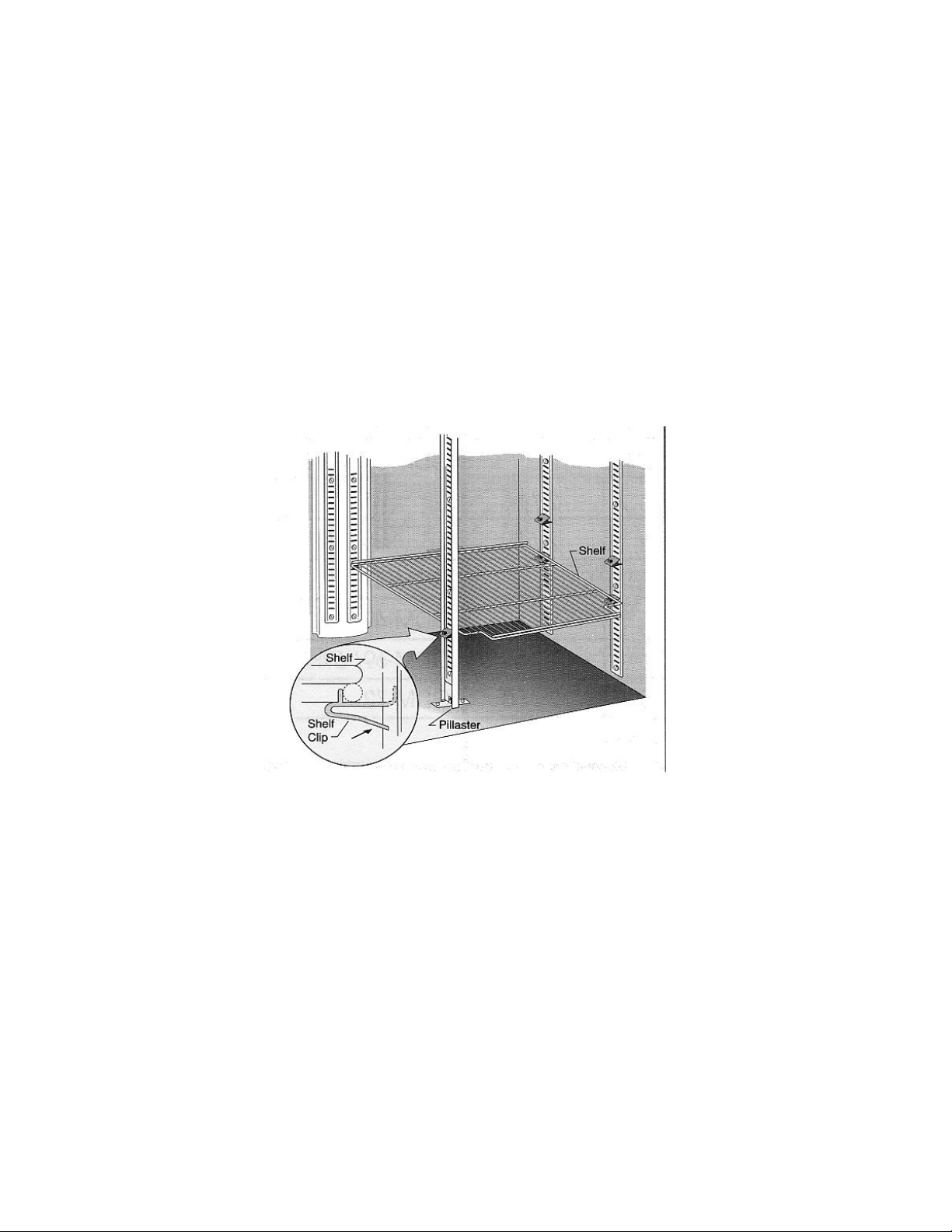
-When loading the top shelf, avoid blocking the evaporator fan(s) (if installed). There should
be at least 4 inches of clearance below the fan(s) to allow proper air flow.
-Do not overload the unit. A full load is about 70 to 75% full. Additionally, the load should be
distributed evenly from top to bottom and side to side for best results.
-Minimize the time the door is open. On top of letting the cold air out, you are also letting
warm, moist air in which can result in more condensation and/or frost in the unit.
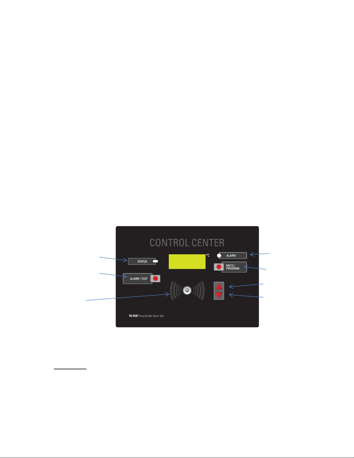
Remember that the units are calibrated to the design temperature range before leaving the
factory. We also do extensive testing to ensure that these temperatures will result in product
temperatures in the desired band. There should be no need to adjust the temperature control
on these units, but if it is necessary, they can be adjusted using the manual thermostat on the
back of the unit.
It is STRONGLY RECOMMENDED that you contact our Technical Support Department prior to
performing any temperature adjustments to ensure the adjustment is necessary and, if so, it
is performed correctly.
IMPORTANT! This refrigerator / freezer has a pre-drilled 3/8 inch port hole on the back wall for
the future installation of independent monitor probe. To install the independent monitor probe:
remove the white plug from the interior back wall and exterior wall, run the probe through the
hole, trim the white plug to the probe size, seal the hole with silicone and replace white plugs.

Part number 20057, Rev 0
8
DIGITAL TEMP DISPLAY (“-DTD” MODEL)
The digital temp display provides a clear and digital temp readout. The probe is placed within
the glycol to simulate the product temp inside the chamber.
Displaying °F or °C: Remove the plastic panel located below the solar panels by using a blunt
tipped tool. Slide the °C/°F switch to °C to display the temperature in Celsius or to °F to display
the temperature in Fahrenheit. Replace the plastic panel.
Display Message: MIN or MAX appearing on the display or HHH flashing on the display
indicates that the unit is in a power lock-up mode and that the unit must be reset. To reset the
unit and clear the message from the display, remove the plastic panel located below the solar
panels by using a blunt tipped tool. Press the Reset button located to the left of the °C/°F
switch. Replace the plastic panel.
Battery Replacement: A faint display, no display, erratic readings, or operational difficulties
indicate that the battery should be replaced. Remove the battery cover, located on the back of
the unit, by turning it 1/8 of a turn counter-clockwise. Replace the battery with a new 1.5C, G-
13 battery. Equivalent battery replacements are: RAYOVAC RW42, DURACELL D357, and
EVEREADY 357. Insert the battery with the positive side facing you. Replace the battery cover.

Part number 20057, Rev 0
9
CONTROL CENTER - TEMPERATURE MONITOR SYSTEM (“-DA” MODEL)
The temperature control center (monitor) system on the front of the unit provides the
following functions-
-to provide an indication of the sample temperature inside of the compartment
-to provide a local alarm at the unit in the event an out of range temperature exists
-to provide the ability to connect remote systems to provide remote alarms or
notifications in the event of an out of range temperature.
-to provide the ability to adjust setpoints, as well as program and test other parameters
associated with the alarm system (i.e. delay times, system status).
-a battery backup, which will maintain the alarm system for several hours after a power
failure to allow for continued alarm and notification functions.
The temperature monitor system does NOT control the temperature of the unit. That function
is performed by the Microprocessor Digital Temperature Control, which is preset at the factory
and should not need to be adjusted by the user.
CONTROL CENTER PANEL
The LCD Display shows the temperature in ºC
In the event of a loss of power, the display shows a BAT message to indicate that the
monitor is running on the battery. If the battery is low, the BAT message will blink.
ALARM
MUTE/PROGRAM
UP button
DOWN button
STATUS tri-color LED
ALARM/TEST button
Alarm beeper

Part number 20057, Rev 0
10
The STATUS tricolor LED shows the status of the unit.
Green = normal run mode
Amber = program mode
Red = temperature is out of range (The light blinks off briefly each second to show the
unit is active)
The ALARM/TEST push-button interrupts line power, to allow testing of the battery and the
alarm relay.
The bright red ALARM LED shows alarm conditions.
In alarm mode, it flashes every half-second.
In alarm mute mode, it gives a short blink every second.
In battery mode, it gives a short blink every two seconds.
The BEEPER shows alarm conditions and user activity.
In alarm mode, it gives a long beep.
In alarm mute mode, it gives a short chirp.
It gives an audible tick to indicate a button has been pressed.
The MUTE/PROGRAM button has three functions.
In Normal Run mode, if the unit is beeping, pressing the button will mute the beeper for a
preset time. Each time the button is pressed the mute time resets.
Holding the button down for two seconds takes the unit out of Normal Run mode and into
Programming mode. At the same time, it mutes the beeper.
When in Programming mode, pressing the button steps the unit through the various
programming parameters.
The UP button has a different function for each operating mode.
In Normal Run mode, pressing the button causes the high temperature set point to be
displayed.
In Programming mode, pressing the button increases the displayed parameter value.
The DOWN button has a different function for each operating mode.
In Normal Run mode, pressing the button displays the low temperature set point.

Part number 20057, Rev 0
11
In Programming mode, pressing the button decreases the displayed parameter value.
BASIC OPERATION
The Control Center Monitor has two modes: NORMAL RUN MODE and PROGRAMMING MODE.
In Normal Run mode, the display shows the temperature that the probe is reading to the lowest
whole number, i.e., if it shows a value of 10.0ᵒ, the actual temperature can range from 10.0 to
10.9.
Press the UP button to cause the display to show the high temperature set point.
Press the DOWN button to cause the display to show the low temperature set point.
The Control Center compares the probe’s temperature reading to HIGH and LOW temperature
setpoints. The STATUS LED glows green when the probe reads an in-range temperature
(between the two setpoints) and red when the temperature is out of range (equal to or outside
the setpoints).
The Control Center will not declare an alarm until the out-of-range state has continued for a
specified time (the “alarm delay”). This alarm delay time is designed to prevent transient,
nuisance alarms.
When an alarm condition is declared, the BEEPER and ALARM LED will both activate. Press the
MUTE/PROGRAM button to stop the beeper for a specified time, changing the sound to short
‘chirps’. When the temperature goes back within range, and there are no out-of-range readings
for thirty seconds, the chirping stops and the MUTE/PROGRAM button resets. If another out-
of-range condition then occurs, the beeper will again start at full volume.
After the user-programmable “SILENCE” parameter times out, if the alarm condition still exists,
the beeper will annunciate again at full volume until MUTE/PROGRAM is pushed.
Battery Back-Up (B)
The Control Center has a battery back-up option. It ships with the battery in place and
connected. Remove the white nylon screw located on the lower left side of the module to
activate the battery option.
When line power is present, all of the normal features of The Control Center are operating.
When line power is lost, the battery provides power to maintain two important functions:
Operate the audio and visual alarms. They flash/beep less frequently than usual, in order to
avoid draining the battery.
Continue to display the temperature of the area being monitored. The display will flash, to
save power.

Part number 20057, Rev 0
12
Testing the battery:
The battery recharges when the unit is plugged into line power. To test the battery, push the
ALARM/TEST button on the front panel. The following should happen:
The ALARM LED will flash red.
The beeper alarm will begin to chirp.
The remote alarm relay will switch.
PROGRAMMING
To program The Control Center Monitor:
1. Hold the MUTE button for two seconds to bring the unit into Programming mode.
2. The display will show the first parameter that can be programmed (high temperature limit).
The name of the parameter will flash, then the current value of that parameter.
3. To change the value of a parameter, press the UP or DOWN buttons. Pressing either button
will change the parameter value by one count.
4. Holding either button for half a second will change the parameter value by 10 counts. It will
continue to step by 10 for each push, so long as the pushes occur within a short period.
5. Once the Monitor is in Programming mode, each time the Mute button is pressed, the
display steps to the next parameter. As the display steps to the next parameter, the value
of the previous parameter is saved. Once the final parameter is reached, pressing the
MUTE button returns the monitor to Normal Run mode, saving the final parameter.
Description of Parameters for Control Center:
Hi (High Limit)
In Normal Run mode, the alarm will trigger if the probe reads a temperature equal to or above
the high temperature limit. The high temperature limit cannot be set above the operating
temperature range of the unit.
Lo (Low Limit)
When in Normal Run mode, the alarm will trigger if the probe reads a temperature equal to or
below the low temperature limit. The low temperature limit cannot be set below the operating
temperature range of the unit.
Ad (Alarm Delay)
The Control Center will not declare an alarm until the out-of-range state has continued for a
specified time (the “alarm delay”). This alarm delay time will prevent transient nuisance
alarms. The alarm delay time can be set for 0 to 30 minutes.

Part number 20057, Rev 0
13
rd (Relay Delay)
If there is an alarm condition, the relay contacts will switch. The relay delay parameter allows
the user to set the amount of time delay from the start of the alarm condition to the time the
relay contact switches. This keeps the relay from switching during short “nuisance alarms”.
The operator may set the relay delay time for 0 to 30 minutes.
SIL (Alarm Silence, or Alarm Mute Time)
This parameter sets the number of minutes the beeper will “chirp” when the mute button is
pressed during an alarm condition. After the Silence Time elapses, if the alarm condition still
exists, the beeper will begin to sound at full volume again. This parameter can be set from 5 to
120 minutes.
To view the Highest temperature
HOLD both the Hi and the Lo buttons together
(Observe “H L” on display)
Continue holding Hi and release the Lo button
The Status LED will switch to Amber to indicate that the displayed temperature is not the
current temperature, but the saved temperature.
To view the Lowest temperature
HOLD both the Hi and the Lo buttons together
(Observe “H L” on display)
Continue holding Lo and release the Hi button
The Status LED will switch to Amber.
To manually reset the Highest and Lowest to the current temperature
HOLD both the Hi and the Lo buttons together
(Observe “H L” on display)
Press the Mute/Program button
(Observe all segments on (1888)

Part number 20057, Rev 0
14
Remote Alarm Contacts
The Remote Alarm Relay is a single-pole double-throw (SPDT) relay that changes state
(switches) with the loss of line power or with the presence of an alarm condition.
NOTE: The relay is rated for pilot duty operation only. Do NOT use it for control switching. The
relay contacts and connections are rated at 30v/1A.
In normal applications, the relay signals remote alarms or central monitoring systems that an
alarm condition has occurred at the unit being monitored.
The relay will “pull-in” when line power is present. If an alarm condition lasts for a designated
time (the “relay delay”), the relay will “drop out”, causing the relay contacts to switch. If the
alarm condition does not last long enough for the relay delay to time out, the relay will not go
into its alarm position. The relay will also “drop out” if power to the alarm is lost, acting as a
power loss detector.
The diagram below is an example of hooking up our external relay output to a remote alarm.

Part number 20057, Rev 0
15
CHART RECORDER OPERATION (“-CR” MODEL)
CHANGING THE CHART PAPER
Press and hold the "change chart" button (#3) for approximately one (1) second until the pen
begins to move to the left of the chart and then release the button. Wait until the pen has
moved completely off of the chart. To remove the chart paper, unscrew (counter-clockwise) the
chart "hub" knob at the center of the chart. Remove the old chart paper and position the new
one so that the correct time line coincides
with the time line groove on the chart plate. Refer to Figure 5 for the location of the time line
groove.
Re-attach the chart "hub" knob and screw securely (by hand) against the chart. Press and hold
the "change chart" button (#3) again for approximately one (1) second until the pen begins to
move back onto the chart and then release the button. Check to make sure that the pen is
marking on the chart paper. If it is not, then carefully adjust the pen arm to establish contact
with the paper.
REPLACEMENT OF PEN
Note: In non-inking units, (that is, when using pressure sensitive recording chart paper)
replacement of the pen is not necessary.
Recorders that are equipped with fiber tipped cartridge pens will have a cartridge that is color
coded "red" to designate pen number one (1) and an optional cartridge that is color coded
"blue" to designate pen number two (2). The pen cartridge is securely fastened to the metal
pen arm using a special "U" clip tab.
For ease of replacement, it is suggested that the two (2) screws that hold the pen arm be
loosened and the pen cartridge and metal pen arm be removed as an assembly. Refer to Figure
5 for the location of the pen arm screws. Unsnap the plastic "U" clip tab of the pen cartridge
from the metal pen arm, remove and discard the old pen cartridge. Replace the new cartridge
by opening the hinge and snapping it securely around the metal pen arm. Refer to the following
figure.
Figure 1: Pen Arm Assembly.

Part number 20057, Rev 0
16
PEN ARM CALIBRATION
To check and/or adjust the recording pen(s) calibration to the outer most temperature
graduation of the chart, press and hold the "change chart" button (#3) until the pen begins to
move off of the chart. Once the pen(s) has moved off of the chart, again press and hold the
"change chart" button (#3) until the pen begins to move back onto the chart. The pen should
briefly stop at the outer most temperature graduation of the chart before continuing onto the
chart to begin recording. If the pen does not stop exactly at this location on the chart, it can be
adjusted or "calibrated" by using the left (#1) or right (#2) arrow buttons (refer to Figure 3).
When the pen moves back onto the chart and briefly stops, you will have approximately five (5)
seconds in which to adjust the pen's position using the left and right arrow buttons of Figure 3.
On multiple pen recorders, each pen will move (one-at-a-time) onto the chart briefly stopping
at the outer most temperature graduation of the chart at which time the pen's position can be
adjusted by using the left (#1) or right (#2) arrow buttons. When the time to adjust the position
of the first pen has expired, the second pen will move onto the chart briefly stopping at the
outer most temperature graduation of the chart at which time the second pen's position may
be adjusted.
Each time the chart paper or fiber tip pen cartridge is changed, you should make sure that each
pen stops at the outer most temperature graduation of the chart paper. Otherwise, this pen
offset will cause the unit to record an incorrect temperature on the chart.
TEMPERATURE RECORDER CALIBRATION CHECK
This recorder has been accurately calibrated at the factory. Before making any adjustments, this
instrument should be in service for 24 hours. Thereafter, if any adjustment is required, perform
the following procedure. Important: DO NOT immerse a Temperature/Humidity probe in any
solution.
1. Place a Certified Test Thermometer(s) in a solution bottle(s) alongside the recorder's sensor
probe(s).
2. Once the temperature has leveled out, compare the position of the pen on the recorder to
the test thermometer's reading.
2a. For two (2) pen recorders, also compare the second thermometer's reading to the second
pen of the recorder.
3. If an adjustment is required, use the left (#1) and right (#2) arrow push buttons on the
recorder to calibrate (or move) the pen's position on the chart to correspond to the

Part number 20057, Rev 0
17
temperature of the solution. The arrow buttons must be held for approximately five (5) seconds
before the pen will begin to move.
3a. For two (2) pen recorders, you must first select the pen that you wish to calibrate. This is
done by pressing the left (#1) arrow button to select the red pen or the right (#2) arrow button
to select the blue pen. The arrow button must be held down until the green LED light goes out.
After the green LED light goes out, follow the instructions in step #3 above. (Refer to the
following figure for a diagram of the push buttons).
Figure 3: Push Buttons.
.
RECORDER SPECIFICATIONS
INPUT
Nominal Input Voltage: Single Phase 115/230VAC.
Nominal Input Current: 40mA/20mA
Nominal Input Frequency: 50-60 Hz.
BATTERY (Optional)
Battery Type: 9 Volt Alkaline
Low Battery Signaling: Flashing LED
OPERATING ENVIRONMENT
0ºC-40ºC (32ºF-104ºF); 0-95% RH, Non condensing
Pollution Degree: 2
Installation Category: II

Part number 20057, Rev 0
18
QUICK TROUBLESHOOTING GUIDE
Check these items before calling for service
PROBLEM:
POSSIBLE CAUSE / SOULTIONS:
Unit does not run
Electrical circuit is not 110-120V 60Hz.
The power cord is not plugged in.
No power at electrical outlet. Check to make sure
breaker is not tripped or fuse is not blown. Additionally,
make sure unit is not plugged into a Ground Fault Circuit
Interrupter (GFCI) type of outlet.
Unit does not maintain at the
proper temperature
Check the room temperature. We recommend the
refrigerator or freezer should be placed in the air
conditioned room between 65°F to 85°F. If the room
temp is too warm, the refrigerator or freezer may not be
able to maintain the interior temp at proper range.
Door is not closed properly.
Amount of stored product is overloaded.
Product replacements are pushed against rear wall or
interrupted the proper refrigerator air circulation. For
the proper air circulation, place the products evenly on
each shelf. Do not push against the refrigerator’s rear or
side walls.
Evaporator is blocked by frost or ice. Remove the
products, unplug the refrigerator or freezer power, and
allow the unit to defrost. If the problem still exists, call
for service.
3rd party thermometer is placed incorrectly. For proper
temperature monitoring, the thermometer should be
place in the middle of refrigerator.
PLEASE NOTE! Prior to shipment, each refrigerator and freezer
has been calibrated and tested at proper temperature range.
Appliance runs too long
Prolong door openings.
Control set too cold.
Room temperature is high which will make the unit work
harder to keep cool.
Temperature of external wall
surface is warm
The exterior walls can be as much as 30 degrees warmer
than room temperature due to the embedded
condenser coils. This is normal when the unit is
operating.

Part number 20057, Rev 0
19
PROBLEM:
POSSIBLE CAUSE / SOULTIONS:
Compressor noises
Compressor may be overheated. Please check the room
temp and ensure the range is within 65°F to 85°F. If the
problem still exists, call for service.
Moisture collects inside
Door gasket is not sealing properly. Check for debris,
cracks, and items passing through door at the gasket.
The freezer is facing a doorway or is underneath of air
conditioning vent. Relocate the unit or redirect air vent.
Too many door openings. Minimize time door is open.
Hot, humid weather increases condensation.
Make sure there is a water trap (U-shaped loop) in the
drain tube near the compressor. This will “trap” a small
amount of water in the loop and prevent air from
entering the chamber through the tube.
Moisture collects on outside
surface
Hot, humid weather increases condensation.
As humidity decreases, moisture will disappear.
Odor inside the unit
Interior needs to be cleaned. See section on
maintenance and cleaning in this manual.
Make sure product containers are tightly sealed to
prevent leakage
Door will not close
The unit is not level. Refer to the Leveling section at the
beginning of this manual
Check for dirt and debris or items passing through the
door seal.
MOISTURE DURING THE SUMMER SEASON
The amount of moisture, condensation, or high humidity related issues increase during the summer
and, in most cases, will self-resolve when the weather cools down. Please note a refrigeration
system will NOT generate moisture or water but simply condenses the moisture that is already in
the chamber. Keeping the unit in an air conditioned, low humidity space will resolve many issues.
Other things you should check
1. Location of the freezer (See Quick Troubleshooting Guide above)
2. Door sealing and frequency of door opening event (See Quick Troubleshooting Guide above)
3. Make sure there is a water trap (U-shaped loop) in the drain tube near the end. This will
“trap” a small amount of water in the loop and prevent air from entering the chamber
through the tube.
Before calling the manufacturer’s Technical Support Department, please have the unit’s model
and serial number ready as well as the problem description. The model and serial number is
located on the serial tag which can be found on the interior left upper wall of the unit.

Part number 20057, Rev 0
20
MAINTENANCE AND CLEANING
Freezers should be defrosted whenever ¼ to ½ inch of frost has accumulated. Use the
procedures in the defrosting section starting at the bottom of this page for best results.
Refrigerators require little maintenance but should be cleaned periodically to keep them running
efficiently. Use the cleaning agents and suggestions in this table for best results.
CLEANING
PART
CLEANING AGENTS
TIPS AND PRECAUTIONS
Interior and Door
Liners
Soap and water
Baking soda and water
Use 2 tablespoons of baking soda in 1 quart of
warm water
Be sure to wring excess water out of sponge or
cloth before cleaning around controls, light bulb
or any electrical parts.
Door Gaskets
Soap and water
Wipe gaskets and their seating surfaces with a
clean soft cloth
Shelves
Soap and water
Do not wash removable shelves in dishwasher
Exterior and
Handles
Soap and water
Non Abrasive Glass
Cleaner
Do not use commercial household cleaners,
ammonia, or alcohol to clean handles
Use a soft cloth to clean smooth handles
Do not use a dry cloth to clean smooth handles
DEFROSTING (FREEZERS AND COMBO UNITS ONLY)
It is important to defrost and clean the freezer when ¼ to ½ inch of frost has accumulated. Frost
may tend to accumulate faster on upper part of the freezer due to warm, moist air entering the
freezer when the door is opened. Between defrost evolutions; you can minimize frost build-up
by using a plastic scraper to remove frost. Scrape with a pulling motion. Never use a metal
instrument to remove frost. Never use a damp cloth or wet hands as they will stick to the inside
surfaces when cold. When defrosting becomes necessary, disconnect freezer from power
source by unplugging to avoid electrical hazard. DO NOT ADJUST THE THERMOSTAT. Remove
the product and leave the door open while defrosting the freezer.
This manual suits for next models
8
Table of contents
Other VWR Refrigerator manuals
Popular Refrigerator manuals by other brands

Fust NOVAMATIC
Fust NOVAMATIC KS-TF 2920-IB FRESH Instructions for installation, use, maintenance

Zanussi
Zanussi ZO 33 S Instruction booklet

LG
LG LSSB2692 SERIES owner's manual

Subzero
Subzero AMPLIFIER Series Use and care guide

Whirlpool
Whirlpool GSS30C6EYW User instructions

Beko
Beko CS 232020 S Instructions for use