Wadkin Bursgreen WB800H User manual

Wadkin Bursgreen WB Bandsaw Range

CONTENT
Specifications 1 Fitting the Fence Rail 9
General Safety Instructions 2 Fitting the Rip Fence 9
Special safety Instructions 3 Set Up 9
Blade safety 4 Setting the Table Stop 9
Use of Extension Leads 4 Setting Up the Blade Tension &
Safety Symbols 5
Safety Symbols Used throughout this
Tracking 10
Setting the Blade Guide 10
Manual 5 Setting the Mobile Wheel Kit 11
Site Considerations 5 Operation 12
General Condition 5 Switch 12
Floor Load 5 Blade Guide 12
Working Clearance 5 Rip Fence 12
Lighting and Outlets 5 Using the Mitre Gauge 12
Dust Collector 5 Tilting the Table to Perform Bevel
Getting to Know your Machine 6
Unpacking 7
Piece Inventory 7
Clean Up 7
Assembly 8
Fitting the Guide Post Handwheel 8
Fitting the Belt tension Handwheel
Cuts 13
Maintenance 13
Changing the Blade 13
Replacing the Drive Belt 13
Cleaning 14
Wiring Diagram 14
Trouble-Shooting 15
Lever 8 Part Lists & Diagram 16
Fitting the Table 8
SPECIFICATIONS
Item
WB500H
WB600H
WB700H
WB800H
Power
Motor
Blade Length
Blade Width
Blade Speed
Throat Capacity
Max Cutting height
Table Size
400V,3~,50Hz
3.5KW,1450rpm
4100 mm
6 ~38 mm
22
m/s
e5
c
00
mm
350 mm
600x500 mm
400V,3~,50Hz
4.0KW,1450rpm
4590 mm
6~38 mm
26 m/sec600 mm
430 mm
700x610 mm
400V,3~,50Hz
4.0KW,1450rpm
5020 mm
6 ~50 mm
26
m/s
e7
c
00
mm
430 mm
1000x700 mm
400V,3~,50Hz
5.5KW,1450rpm
5611 mm
19~50 mm
18 m/sec
800 mm
470 mm
900 x700 mm
Table Tilt
Dust Port
N.W./G.W.
0O~45O
2x100 mm
280/316 kgs
0O~45O
2x100 mm
330/365 kgs
0O~45O
2x100mm
398/437 kgs
0O~45O
2x100mm
441/524 kgs
Packing Size(mm3)
Noise(unloading)
930x725x2140
78 dB(A)
1030x730x2220
78 dB(A)
1130x730x2330
78 dB(A)
2500x730x1320
78 dB(A)
NOTE: The above specifications and the constructions were current at the time this manual was published, but
because of our policy of continuous improvement, we reserve the right to change specifications and the
constructions without notice and without incurring obligations.
1

GENERAL SAFETY INSTRUCTIONS
Please read the following instructions carefully,
failure to do so could lead to serious personal
injury.
When using electric tools, basic safety
precautions should always be followed to reduce
the risk of fire, electric shock and personal injury.
Read all these instructions before operating the
tool and save this user manual for future
reference.
We recommends that this tool should not be
modified or used for any application other than
that for which it was designed. If you are unsure of
its relative applications do not hesitate to contact
us using the telephone number on the back of this
user manual, and we will be more than happy to
advise you.
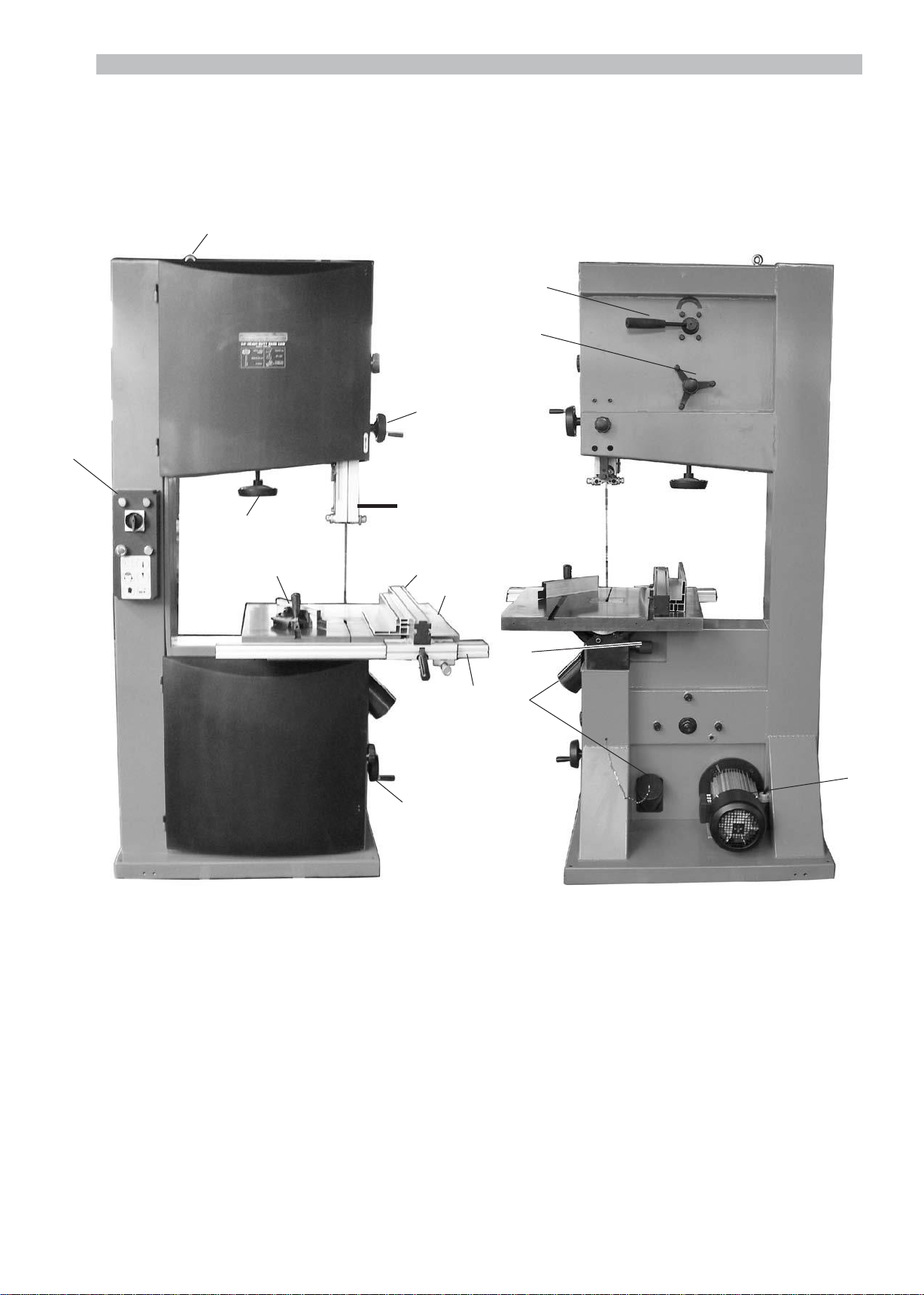
KNOW YOUR POWER TOOL: Read and
understand the owner's manual and labels affixed
to the saw. Learn its applications and limitations,
as well as the potential hazards specific to this
tool.
KEEP WORK AREA CLEAN AND WELL LIT:
Cluttered work benches and dark areas invite
accidents. Floors must not be slippery due to oil,
water or sawdust etc.
DO NOT USE THE SAW IN DANGEROUS
ENVIRONMENTS: Do not use power tools in
damp or wet locations, or expose them to rain.
Provide adequate space surrounding the work
area. Do not use in environments with a
potentially explosive atmosphere.
KEEP CHILDREN AND UNTRAINED
PERSONNEL AWAY FROM THE WORK AREA:
All visitors should be kept at a safe distance from
the work area.
STORE TOOLS SAFELY WHEN THEY ARE NOT
IN USE: All tools should be stored in a dry, locked
cupboard and out of the reach of children.
WEAR THE CORRECT CLOTHING: Do not wear
loose clothing, neckties, rings, bracelets, or other
jewellery, which may get caught in moving parts.
Non-slip footwear is recommended. Wear
protective hair covering to contain long hair. Roll
long sleeves up above the elbow.
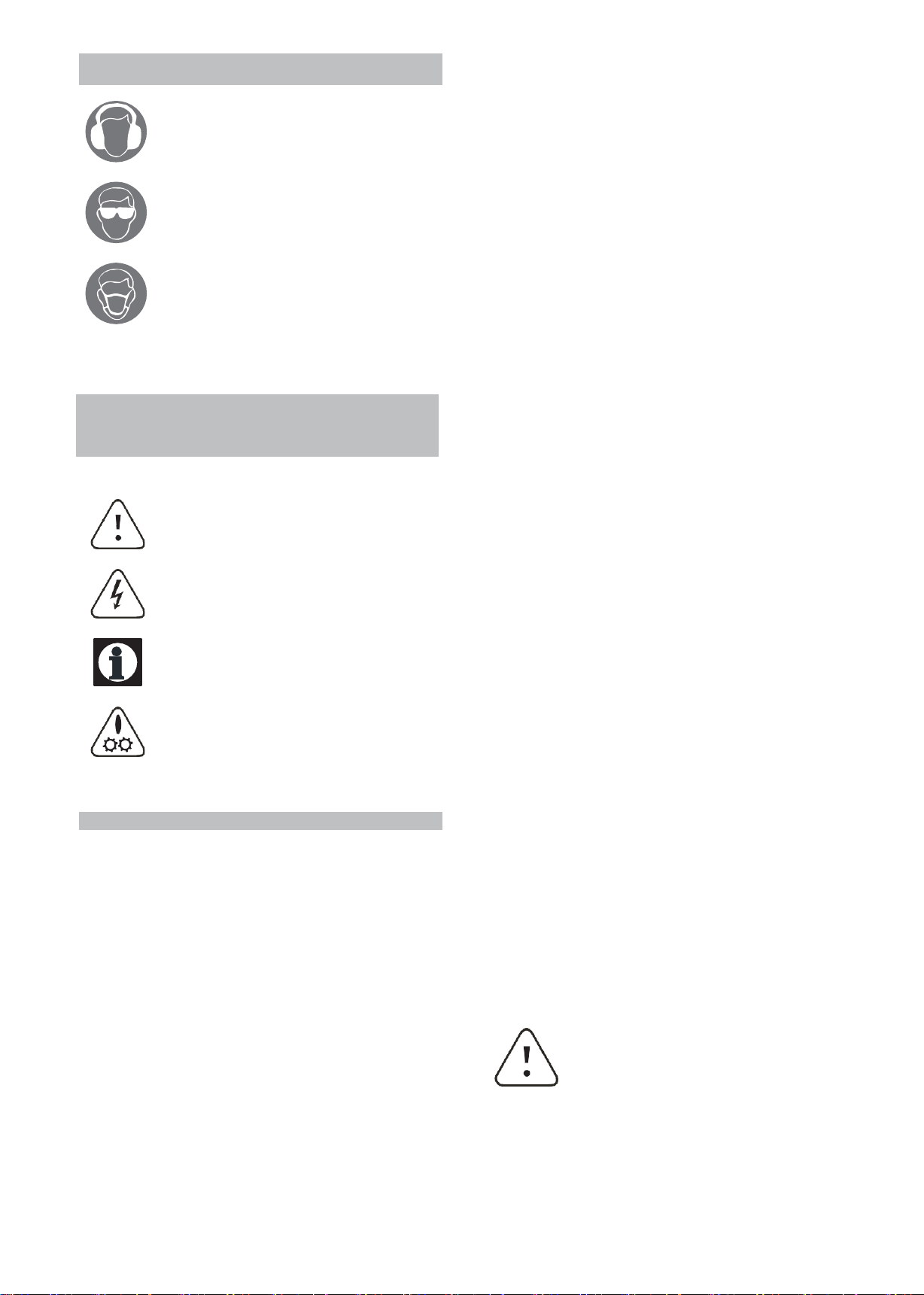
USE SAFETY GOGGLES AND EAR
PROTECTION: Wear CE approved safety goggles
at all times, Normal spectacles only have impact
resistant lenses, they are NOT safety glasses. A
face or dust mask should be worn if the operation
is dusty and ear protectors (plugs or muffs) should
be worn, particularly during extended periods of
operation.
PROTECT YOURSELF FROM ELECTRIC
SHOCK: When working with power tools, avoid
contact with any earthed items (e.g. pipes,
radiators, hobs and refrigerators, etc.). It is 2
advisable wherever possible to use an RCD
(residual current device) at the mains socket.
STAY ALERT: Always watch what you are doing
and use common sense. Do not operate the saw
when you are tired or under the influence of
alcohol or drugs.
DISCONNECT THE TOOL FROM THE MAINS
SUPPLY: When not in use, before servicing and
when changing accessories such as cutters, etc.
AVOID UNINTENTIONAL STARTING: Make sure
the switch is in the OFF position before
connecting the tool to the mains supply.
NEVER LEAVE THE TOOL RUNNING /
CONNECTED WHILST UNATTENDED: Turn off
the tool and disconnect it from the mains supply
between jobs. Do not leave machine until it comes
to a complete stop.
DO NOT ABUSE THE MAINS LEAD: Never
attempt to move the saw by means of the mains
lead or pull it to remove the plug from the mains
socket. Keep the mains lead away from heat, oil
and sharp edges. If the mains lead is damaged, it
must be replaced by the manufacturer or its
service agent or a similarly qualified person in
order to avoid unwanted hazards.
CHECK FOR DAMAGED PARTS: Before every
use of the tool, a guard or other part that is
damaged should be carefully checked to
determine that it will operate correctly and
perform its intended function. Check for alignment
of moving parts, free running of moving parts,
breakage of parts, and any other conditions that
may affect its operation. A guard or other part
that is damaged should be correctly repaired or
replaced by an authorized service centre unless
otherwise indicated in this instruction manual.
Have defective switches replaced by an
authorized service agent. Do not use the tool if the
switch does not turn it on and off.
KEEP ALL GUARDS IN PLACE: And in full
working order.
MAINTAIN TOOLS WITH CARE: Keep tools sharp
and clean for the best and safest performance.
Follow instructions for lubricating and changing
accessories. All extension cables must be
checked at regular intervals and replaced if
damaged.
USE ONLY RECOMMENDED ACCESSORIES:
Consult this user manual for recommended
accessories. Follow the instructions that
accompany the accessories. The use of improper
accessories may cause hazards and will
invalidate any warranty you may have.
REMOVE ADJUSTING KEYS AND WRENCHES:
Form a habit of checking to see that keys and
adjusting wrenches are removed from the tool
before every use.

e
of moving parts, free running of moving parts,
accessories. Follow the instructions that
DO NOT ABUSE THE MAINS LEAD: Never be carried out by qualified persons using original
attempt to move the saw by means of the mains spare parts, otherwise this may result in
lead or pull it to remove the plug from the mains considerable danger to the user.
socket. Keep the mains lead away from heat, oil
and sharp edges. If the mains lead is damaged, it
must be replaced by the manufacturer or its
service agent or a similarly qualified person in
order to avoid unwanted hazards. SPECIAL SAFETY INSTRUCTIONS
CHECK FOR DAMAGED PARTS: Before every 1. Some wood and wood type products, especially
use of the tool, a guard or other part that is MDF (Medium Density Fibreboard) can produce
damaged should be carefully checked to dust that can be hazardous to your health. We
determine that it will operate correctly and recommend the use of an approved face mask
perform its intended function. Check for alignment with replaceable filters when using this machine in
breakage of parts, and any other conditions that
may affect its operation.A guard or other part that 2. Approved safety glasses or goggles and ear
is damaged should be correctly repaired or defenders must be worn when using the saw.
replaced by an authorized service cent r unless
otherwise indicated in this instruction manual. 3. Ensure that the band saw is securely fastened
Have defective switches replaced by an to its base and wherever possible secure the base
authorized service agent. Do not use the tool if the to the floor - When selecting a location for the
switch does not turn it on and off. band saw consideration needs to be given to the
KEEP ALL GUARDS IN PLACE: And in full
working order.
MAINTAIN TOOLS WITH CARE: Keep tools sharp
and clean for the best and safest performance.
Follow instructions for lubricating and changing
size of material to be cut and the area around the
Band Saw.
4. Do Not attempt to use for wet cutting operations
a fatal electric shock could occur. This machine is
to be used for dry cutting only.
accessories. All extension cables must be 5. Do Not over tension the drive belt, the drive belt
checked at regular intervals and replaced if will last longer if the tension is released after each
damaged. use.
USE ONLY RECOMMENDED ACCESSORIES: 6. Do Not allow sawdust to build up around the
Consult this user manual for recommended motor or inside the machine. A build up of sawdust
accompany the accessories. The use of improper
accessories may cause hazards and will
invalidate any warranty you may have.
REMOVE ADJUSTING KEYS AND WRENCHES:
7.
Do Not stop the blade by forcing the work piece
against it or by using sideways pressure.
Form a habit of checking to see that keys and 8. Keep Guards in place and in good working
adjusting wrenches are removed from the tool order.
before every use.
9.
Always ensure that the blade guide rollers are
DO NOT OVERREACH: Keep proper footing and set correctly.
balance at all times.
10.
Do Not start the machine with the blade in
USE THE RIGHT TOOL: Do not use the tool or contact with the work piece.
attachment to do a job for which it was not
designed. 11. Check the work piece for any protruding nails,
DO NOT FORCE THE TOOL: It will do the job
better and more safely at the rate which it was
screw heads or anything that could damage the
blade.
designed. 12. Do Not attempt to modify the machine or its
DO NOT OPERATE POWER TOOLS IN accessories in any way.
EXPLOSIVE ATMOSPHERES: Do not use the tool 13. Do Not use excessive force when feeding the
in the presence of flammable liquids, gases, dust work piece to the blade, feeding the work piece
or other combustible sources. Power tools may gradually will reduce wear on the machine and
create sparks which can ignite the dust or fumes. blade, increasing its efficiency and operating life.
DO NOT EXPOSE THE TOOL TO RAIN OR USE 14. For your safety; remove the chippings and
IT IN WET CONDITIONS: Water entering a power work debris etc. from the table top and from inside
tool will greatly increase the risk of electric shock. the extraction port before each operation.
HAVE YOUR TOOL REPAIRED BY A QUALIFIED 15. Keep hands out of path of saw blade, never
PERSON: The tool is in accordance with the reach around saw blade.
relevant safety requirements. Repairs should only 3
addition to using the dust extraction facility.
is a fire hazard.

4
16.
Before making the first cut using the saw, let it Always release the blade tension, when the
run for a while; Watch for vibration or wobbling machine is not in use.
that could indicate poor installation or a poorly
balanced blade. Adjust or replace as necessary. Always wear gloves and eye protection when
fitting or removing blades.
17.
Allow the blade to run up to full speed before Always uncoil blades in spacious areas, away
cutting. from other people, and take great care.
18.
Stop operation immediately if you notice Always keep looped blades secure with tie
anything abnormal. wires.
19.
Wait for the saw blade to stop completely and Always keep fingers away from moving blades.
remove the plug from the mains supply before
servicing or adjusting tool.
20.
Be alert at all times, especially during Use of extension leads:
repetitive, monotonous operations. Don't be lulled DO NOT use 3 core extension leads or reels,
into a false sense of security. Blades are always use a 4 core extension lead or reel with
extremely unforgiving. an earth.
21.
Use of improper accessories may cause Always unwind any extension leads fully.
damage to the saw and surrounding area as well For extension leads up to 15 metres use a wire
as increasing the risk of injury. cross section of at least 1.5 mm².
22.
Turn off the saw and wait for it to complete For extension cords over 15 metres but less than
stop before moving work-piece or changing 40 metres use a wire cross section of at least 2.5
settings. mm².
23.
Do not modify the saw to do tasks other than Always replace a damaged extension lead
those intended. before using the band saw.
24.
Keep the site free of tripping hazards. Ensure Protect your extension cord from sharp objects,
adequate lighting conditions. excessive heat and damp or wet locations.
25.
The saw must only be operated with all
correctly mounted guards etc. CAUTION: The warnings and cautions
26.
Never use cracked or distorted saw blades -
Only user sharp saw blades.
27.
Use a push stick when rip sawing narrow work-
piece.
mentioned in this user manual can not
cover all possible conditions and
situations that may occur. It must be
understood by the operator that common
sense and caution are factors which
cannot be built into this product, but must
be applied.
Blade Safety:
Use only blades that are recommended by the
manufacturer.
Do Not use blades that are deformed or have
missing teeth, this is highly dangerous and could
result in a serious accident to the operator and
bystanders as well as damaging the machine.
Only use blades that are recommended by the
supplier and that are in good condition.
Ensure that the directional arrow, if marked on
the blade corresponds with the rotational
direction of the motor, the teeth of the blade
should always point downward when viewed
from the front of the saw.

5
SAFETY SYMBOLS USED THROUGHOUT THIS
MANUAL
SAFETY SYMBOLS Floor Load
When using the saw always ensure the
operator as well as those in the area
wear ear protection.
When using the saw always ensure the
operator as well as those in the area
This machine represents a moderately large
weight load in a small footprint. Most commercial
shop floors will be adequate for the weight of the
machine. Some floors may require additional
support. Contact an architect or structural
engineer if you have any question about the ability
of your floor to handle the weight.
wear eye protection. To ensure sufficient upright stability of the
machine it should be bolted to floor. For this
Some wood and wood composites have
the potential to be highly toxic; always
wear a face mask when operating saw.
purpose 4x12mm diameter holes are provided
in the machine' s base plate.
Working Clearances
Working clearances can be thought of as the
distances between machines and obstacles that
allow safe operation of every machine without
limitation. Consider existing and anticipated
machine needs, size of material to be processed
through each machine, and space for auxiliary
stands and/or work tables. Also consider the
Danger / Caution: Indicates risk of relative position of each machine to one another
personal injury and/or the possibility of for efficient material handling. Be sure to allow
damage. yourself sufficient room to safely run your
machines in any foreseeable operation.
Warning: Risk of electrical injury or Lighting and Outlets
damage!
Note: Supplementary information.
Drawing-in / trapping hazard! Risk of
personal injury to body parts or clothing
by being drawn into the rotating saw
blades.
Lighting should be bright enough to eliminate
shadow and prevent eye strain. Electrical circuits
should be dedicated or large enough to handle
combined motor amp loads. Outlets should be
located near each machine so power or extension
cords are not obstructing high-traffic areas. Be
sure to observe local electrical codes for proper
installation of new lighting, outlets, or circuits.
Dust Collector
As a rule, this machine must be vacuumed during
SITE CONSIDERATIONS use. A time relayed socket is available as an
accessory. In addition, the vacuum performance
General Condition: must be sufficient to achieve the required
1.
Electrical connection: Steady state voltage:
0.9-1.1 of nominal voltage.
Frequency: 0.99-1.01 of nominal frequency
continuously; 0.98-1.02 short time
2.
Altitude are not exceeding 1000m,
Maximum ambient air temperature is +40 OC,
minimum ambient air temperature is not less
negative pressures and a maximum air speed of
20m/sec at the connector.
Read the manual before assembly
Than+5 OC, and operation. Become familiar with
Storage and transportion temperature range is -
15 OC~+55 OC.
The relative humidity does not exceed 50% at a
maximum temperature of +40 OC, higher
relative humidity may be permitted at lower
temperature (e.g. 90%@ 20 OC).
the machine and it's operation before
beginning any work. Serious
personal injury may result if safety
or operational information is not
understood or followed.

6
GETTING TO KNOW YOUR MACHINE
B
O
A.
Lift Ring I. Fence Rail
B.
Switch Box J. Belt Tension Handwheel
C.
Blade Tension Handwheel K. Quick Release Lever
D.
Guide Post Handwheel L. Blade Tracking Lock knob & Star-
E.
Blade Guide & Guard Knob
F.
Mitre Gauge M. Table Tilting Knob
G.
Rip Fence N. Dust Ports
H.
Table O. Motor
A
K
L
D
C
E
F
G H
M
I
N
J

7
UNPACKING
The Heavy-Duty Bandsaw is shipped from the
manufacturer in a carefully packed crate. If you
discover the machine is damaged after you have
Lifts out the bandsaw from crate with crane or
forklift.
signed for delivery, please call Customer Service Clean Up
immediately for advice. When you are completely
satisfied with the condition of your shipment, you
should inventory its parts. The unpainted surfaces are coated with a oil to
protect them from corrosion during shipment.
The Heavy-Duty Bandsaw Is a
heavy machine. DO NOT over-
exert yourself while unpacking or
moving your machine you will
need assistance and power
equipment. Serious personal
injury may occur if safe moving
methods are not followed.
Some metal parts may have sharp
edges on them after they are formed.
Please examine the edges of all metal
parts before handling them. Failure to
do so could result in injury.
Remove this protective coating with a solvent
cleaner or citrus-based degreaser. To clean
thoroughly, some parts may need to be removed.
For optimum performance from your machine,
make sure you clean all moving parts or sliding
contact surfaces that are coated. Avoid chlorine-
based solvents as they may damage painted
surfaces should they come in contact.
Do not use gasoline or other
petroleum-based solvents to clean
with. They have low flash points which
make them extremely flammable. A
risk of explosion and burning exists if
these products are used.
Piece Inventory
After all the parts have been removed from the
carton, you should have:
–
Bandsaw Unit with Blade
–
Table
–
Fence Rail
–
Fence
–
Dust Port
–
Miter Gauge
–
Push Stick w/ Hold Pin
–
Hardware Bag
(1)
Lift Ring
(1) Hex Nut M10
(1) Flat Washers 10mm
(1 set) 3mm,4mm,5mm,6mm “L” Wrench
To mount the lift ring
Firstly, mount the lift ring(A) on the upper body of
bandsaw with Hex Nut M10 & Washer 10mm.
Many of the solvents commonly used
to clean machinery can be toxic when
inhaled or ingested. Always work in
well ventilated areas far from potential
ignition sources when dealing with
solvents. Use care when disposing of
waste rags and towels to be sure they
do not create fire or environmental
hazards.

8
open wrench.
ASSEMBLY Fitting the table
Fitting the guide post handwheel
Attach the guide post handwheel lever(B) to the
guide post handwheel, tighten it with the 10mm
open wrench.
Fitting the belt tension handwheel lever
Attach the belt tension handwheel lever(C) to the
The table for this bandsaw is very
heavy. Get help when placing it on
the trunnion.
With the help of another person, carefully lift the
table(E) through blade onto the trunnion.
Place 3 M8x30 Allen Screw(F) through the table
trunnion, tighten them to the table.
Then tilts the table to 30O, place 1 M8x30 Allen
Screw(G). Tighten it.
Note: The bolts do not need too tighten at
this point as some adjustment may be
necessary to set the table correctly.
The blade should sit in the centre of the gap
on the table insert, if it does not tap the edge
of the table (either left or right depending on
which way the table needs to go) with a mallet
(a scrap piece of wood and a hammer will
suffice if a mallet is not available) until the
blade is in the correct position.
belt tension handwheel, tighten it with the 10mm Proceed to fully tighten the securing bolts.
Fitting the upper dust port
Fit the upper dust port(D) to the side of lower
wheel housing. Tighten 4 M5x16(D) pan head
screw (washers and nuts inside the housing).
F

9
Fitting the fence rail SET UP
To fit the fence rail, firstly check 4 winged screws Warning! Before carrying out any
and washers(I) supplied into the 4 threaded holes maintenance or adjustments the
on the bottom of the table. machine must be disconnected from
the power supply.
Note: The winged screw only need to be
fitted with a few turns so there is an Setting the table stop
adequate gap to fit the rip fence rail(J).
Line the cut-outs on the fence guide with the
winged screws earlier fitted to the bottom of the
The positive stop under the table allows you to
repeatedly square up the table after adjusting the
table to another angle.
main table. To adjust the positive stop:
Push the fence rail forwards against the front edge 1. Loosen the ratchet lever( M) on the table
of the main table. trunnion
Fully tighten the winged screws to secure. 2. Loosen the hex nut( K) on the positive stop bolt
( L) and lower the stop bolt.
3.
Raise the upper blade guide assembly and
place a 6" machinist's square on the table
against the blade. Notice how far out of square
your table is and approximate this distance by
adjusting the positive stop up or down. Turning
the positive stop raise or lower it. Adjust the
positive stop so the table will stop at a 90°
angle (square) to the blade.
4.
Lock the positive stop by tightening the hex nut.
Do not let the stop turn while tightening the hex
nut. Tighten the ratchet lever( M).
5.
Set the angle pointer to zero on the table tilt
gauge.
Fitting the rip fence
Fit the profile of the rip-fence carrier into the
opposite profile on the rip-fence rail.
Secure it in the desired position by simply
pressing down on the rip-fence locking handle.
L
K
M

10
R
Q
Setting up the blade tension & tracking
Setting up the blade tension
With the power supply disconnected, set the blade
tension with the blade tension handwheel (N).
Rotating the wheel in a clockwise direction will
increase the blade tension and anti clockwise will
decrease the tension. The blade is at the correct
tension if it can be moved approximately 10
mm sideways with moderate hand pressure .
Tracking the saw-blade
Release the blade tracking lock starknob(O).
With the top door open, turn the drive-wheel by
hand.
Continue to turn the drive-wheel and at the same
time turn the blade tracking knob(P).
Turn both the drive-wheel and the blade tracking
knob until the blade is sitting on the centre of the
drive-wheel.
Note: Daily run you can use the blade
tension indicator window to check the
blade tracking.
Once the blade has been correctly set, Turn the
lock knob clockwise to lock into position.
Setting the blade guide
Upper guide:
The lateral support guide blocks should be set so
that they are approximately 0.5 mm away from the
blade.
Loosen the knurled jam nuts(Q) that lock the
adjusting rod for the guide blocks in place.
Rotate the adjusting rod(R) counterclockwise
and slide guide block back. This will allow the
blade to be removed or tracked without
interference.
The rear guide blocks should be set so that they
are approximately 3 mm behind the blade. They
will only come into contact with the blade as the
work-piece is being cut.
Due to the many different sizes of band-saw
blades available, the rear support guide block
needs to have extra movement compared to the
lateral support guide block. This is achieved by
having 2 different points of movement as opposed
to 1 on the lateral guide blocks.
Allen bolt S - This allows the guide assembly
support pole to be moved and should be utilized
when large movement is required.
Allen bolt T - This allows the rear guide block to
move along the channel on the guide assembly
and should be utilized when only a small amount
of movement is required.
N
O
P

11
Loosen the required allen bolt/s.
Move the guide block, guide assembly and/or the
pole until the guide block is set in the correct
position.
Rotate the belt tension handwheel(V) to adjust the
V-belt tension.
Setting the Mobile Wheel Kit (optional)
Place “U” Shape Bracket(6) onto Front Wheel
Re-tighten all of the allen bolts to secure the Kit Ass'y (a). The Front wheel Kit Ass'y
guide block in place. Assembled by factory enclosed the parts
1,2,3,15 and 4.( refer diagram F)
Insert Hex Head Screw M10x70(8) with
washer(9), secure Front Wheel Kit(a) and
Lower guide: Sleeve(10) to work stand.
Insert Special Thread(14) with washer(1) and
secure Front wheel kit.
Secure Rear Castor Frame(11) to workstand
with two Hex Head Screw M10x20(12) &
washer(7).
When move the machine adjust the Allen Bolt
M12x50(5),and raise the machine about 5mm
above floor. Insert the Rear Castor Ass'y(b),
push the lever down and pull the machine
round the workshop.
Loosen the knurled jam nut(Q)and rotated the
adjusting rod to set the lateral guide block.
The rear guide block is adjustment by the allen
screws (U) & (T).
Allen bolt U - This allows the guide assembly to
be moved and should be utilized when large
movement is required.
Allen bolt T - This allows the rear guide block to
move along the channel on the guide assembly
and should be utilized when only a small amount
of movement is required.
Setting the V-belt tension
The V-belt is accessed via the lower door.
Squeeze the center of the V-belt. Note the amount
of deflection. Defelection shoud be approximately
3/4".
V
S
T
T
U
R
Q

12
W
Run light
Power on
light
Power
Switch
Start button
Stop button
Safety limit switch
Key
OPERATION
Switch
Turn the POWER on or off using the Power
Switch.
Turn the machine on using the green button on
the switch box. Turn off the machine off using the
red button, it also with the emergency-stop
function, and they must be unlocked before turn
the machine on.
There are two indicator lights. Red light works
when POWER on. Green light works when
machine run.
Attention!
Your machine is equipped with two safety
limit switches. The bandsaw can only
run when upper & lower doors are closed.
Blade guide
The upper blade guide assembly must be lowered
to just clear of the work piece. To lower the upper
guide loosen the cut depth lock knob (W) and turn
the guide post handwheel (X) to slide the upper
guide assembly down. Re-secure the cut depth
lock knob (W).
Rip fence
Set the rip fence to the desired width (ensure that
the largest section of the material is against the
fence).
For precise cutting, push in the fine adjustment
knob(Y) and turn to desired position, then push
down the rip fence lock handle.
Using the mitre gauge
Make a practice cut with the gauge in the 0°
position then test the cut with a suitable set
square. If adjustment is necessary loosen the
screw that holds the “pointer” and move the
pointer accordingly. The mitre gauge can be used
in either groove in the table. Set the desired angle
on the mitre scale and make the cut securely
holding the work piece to the mitre gauge.
Y
W X

13
A1
N
Tilting the table to perform bevel cuts
To use the table to perform a bevel cut, loosen the
table trunnion locking lever(M) and turn the table tilt
handle(Z) to tilt the table over to the desired angle.
Re-secure the locking lever(M).
Compound mitre cuts can be made by using the
mitre gauge in conjunction with the table tilting
facility.
MAINTENANCE
Changing the blade
Warning! Unplug the machine from the
electrical supply. This ensures that the
bandsaw will not accidentally turn on if the
ON/OFF switch is bumped.
Remove the rip-fence.
Remove the rip-fence rail.
Open both the upper and lower doors.
Turn the blade tension adjustment hand-wheel
(N) to release the tension (if needed).
Turn the blade tension quick release lever (A1)
to fully release the tension of blade.
Remove the blade.
Fit the new blade around both top and bottom
drive-wheels, taking care that the correct size of
blade is being fitted and that the direction of the
blade is also correct.
Caution: Because the blade is an endless
loop it may spring and coil itself into smaller
loops.
Note: The teeth of the blade should be
pointing downwards if the blade has been
fitted in the correct direction.
Return the pressure to the blade by turning the
blade tension quick release lever back to its
original position.
Continue to tension the blade fully by turning the
adjustment hand-wheel.
Replacing the drive belt:
Remove the blade (see above).
Turn the belt tension handwheel to release
tension from the drive belt.
Loosen and remove the drive wheel securing nut
and washer(A2) (located at the rear of the saw).
Z
M

Note: It may be necessary to tap the
threaded section of the shaft with a soft
faced mallet to remove the drive wheel.
Place the new drive belt over the pulley on the
main drive-wheel.
Re-fit the drive-wheel to the saw and fully tighten
the lock nut to secure.
Follow the instructions to re-fit the blade and to
re-tension the drive belt.
Cleaning:
Caution! Before cleaning or carrying out
maintenance work, disconnect the machine
from the power source (wall socket). Never
use water or other liquids to clean the
machine. Use a brush. Regular
maintenance of the machine will prevent
unnecessary problems.
Always remove excess chips and waste debris
from the band-saw, pay particular attention
around the motors air inlets, failure to do so
could result in overheating and even fire.
Periodically clean and lubricate the internal
moving parts of the band-saw such as the rack
and pinion blade guide assembly, belt tension
screw, table tilting assembly and the belt
tension assembly to ensure easy accurate
adjustments.
WIRING DIAGRAM
WARNING!
This machine must be grounded.
Replacement of the power supply cable should only be done by a qualified electrician.
QS Power switch
SB1 Stop button w/Emergency stop
SB2 Start button
SQ1 SQ2 Limit switch
KM Contactor
FR Thermo protector
FU1 FU2 FU3 Fuse 2A
HL1 Power on light
HL2 Run light
TC Transformer
14
V
A2

15
TROUBLESHOOTING
Warning: For your safety, always turn off and unplug the machine before carrying out any
troubleshooting.
Problem
Possible Cause
Remedy
The machine does not work
when switched on:
Damaged mains lead.
Problem with the electrical supply.
Defective switch.
Defective motor.
Check the cable for damage.
Check for power at the mains.
Have the switch checked,
repaired / replaced.
Have the motor checked, repaired
/ replaced.
The blade does not move with
the motor running:
The quick release lever or blade
tension handwheel has not been
tightened.
The blade has fallen from one of
the wheels.
The saw blade has broken.
The drive belt has snapped.
Switch off the motor, tighten the
quick release lever and/or blade
tension hand-wheel.
Open the door and check the
blade, replace as necessary.
Check the blade , replace as
necessary.
Check the belt and replace as
necessary.
The blade does not cut in a
straight line:
Rip-fence for not used or
incorrectly fitted.
Feed rate too fast.
The blade teeth are dull or
damaged.
Blade guides not correctly
adjusted.
Use a fence, check for correct
alignment.
Use lighter pressure on the work-
piece & allow the saw to do the
cutting.
Replace the damaged blade with
a new one.
Adjust the blade guides.
The blade does not cut, or cuts
very slowly:
The teeth on the blade are dull.
Incorrect blade being used for the
type of cut / material.
Wrong speed being used for type
of cut /material.
The blade was mounted in the
wrong direction.
Replace the blade.
Fit the correct blade.
Change the speed of the blade.
Fit the blade correctly.
Sawdust builds up inside the
machine:
This is normal.
Regularly clean out sawdust from
all areas of the saw. Use of an
adequate dust extractor will
minimize this issue.
Table saw vibrates excessively:
Floor surface is uneven.
V-belt is damaged.
Saw blade is damaged.
Loose bolt, Screws, Nuts.
Sit the saw on a level surface.
Replace the V-belt.
Replace the Saw Blade.
Tighten all Hardware.
Fuses or circuit breakers blow
or open frequently:
Motor is overloaded.
Fuses or circuit breakers are
wrong size or defective.
Dull saw blade.
Power Switch or motor is
defective.
Feed work-piece more slowly.
Replace fuses or circuit breakers.
Replace the saw blade.
Have the Power Switch or motor
checked, repaired or replaced.

16
PARTS LIST & DIAGRAM
Note: Always mention the model number in all correspondence regarding your bandsaw or when
ording repair parts.
Parts List (Diagram A)
No
Description
No
Description
A-1
Allen screw M8x35
A-41
Hex nut M5
A-2
Cam shaft
A-42
Hand wheel, belt tension
A-3
Cam base
A-43
Lever
A-4
Thin hex nut M24
A-44
Pan head screw M4x12
A-5
Washer 24mm
A-45
Sliding guard
A-6
Tyre, wheel
A-46
Upper blade guard
A-7
Sunk head screw M6x12
A-47
Bolt guide, guard
A-8
Block bearing
A-48
Spacer, lower wheel
A-9
Bearing 6207
A-49
Cover, upper guard
A-10
Space, upper wheel
A-50
Cover, upper guard
A-11
Inner space, upper wheel
A-51
Spacer
A-12
Upper wheel
A-52
Sunk head screw M5x10
A-13
Shaft, upper wheel
A-53
Rack
A-14
Lower wheel
A-54
Square tube, upper guide
A-15
Spring
A-55
Allen screw M5x45
A-16
Spring seat
A-56
Worm
A-17
Indicator base
A-57
Tread tube
A-18
Washer 30mm
A-58
Mount, upper guide
A-19
Thin hex nut M30
A-59
Ring worm
A-20
Mount, upper wheel
A-60
Set screw M4x5
A-21
Allen screw M6x25
A-61
Gear, upper guide
A-22
Hex nut M6
A-62
Thread, gear
A-23
Bracket upper wheel
A-63
Block, upper guide
A-24
Thread upper wheel
A-64
Allen screw M6x16
A-25
Set screw M6x8
A-65
Mount upper guide
A-26
Hand wheel, upper wheel
A-66
Shaft, upper guide
A-27
Flat washer 8mm
A-67
Hex screw M6x16
A-28
Allen screw M8x12
A-68
Washer 6mm
A-29
Parallel pin
A-69
Brush
A-30
Washer 8mm
A-70
Hex nut M6
A-31
Spring washer 8mm
A-71
Saw blade
A-32
Hex screw M8x16
A-72
Motor belt "A" 1000mm
A-33
Lock cam
A-73
Shaft, lower wheel
A-34
Lever, lock cam
A-74
Special bolt
A-35
Flower screw M10x40
A-75
Bracket Lower wheel
A-36
Star lock knob, wheel tilt
A-76
Washer 16mm
A-37
Washer 10mm
A-77
Spring washer 16mm
A-38
Pointer mount
A-78
Cap nut M16
A-39
Pan head screw m5x16
A-79
Hex screw M8x180
A-40
Washer 5mm
A-80
Allen screw M8x30

17
Parts List (Diagram A cont. )
No
Description
No
Description
A-81
Block, pulley
A-100
Scale, table tilt
A-82
Motor pulley
A-101
Table trunion, upper
A-83
Set screw M8x10
A-102
Allen screw M8x30
A-84
Flat key
A-103
Allen screw M10x20
A-85
Motor
A-104
Ratchet lever, table tilt
A-86
Hex nut M8
A-105
Block trunion
A-87
Ring circle 20mm
A-106
Pointer tilt
A-88
Washer 20mm
A-107
Lock shaft, trunion
A-89
Bearing 6204
A-108
Washer, lock shaft
A-90
Ring circle 42mm
A-109
Knob, table tilt
A-91
Tension pulley
A-110
Set screw M8x8
A-92
Shaft tension pulley
A-111
Gear, table tilt
A-93
Collar, tension rod
A-112
Table trunion, lower
A-94
Inner space, lower wheel
A-113
Lock nut M10
A-95
Thread tension rod
A-114
Trust bearing 8201
A-96
Washer 12mm
A-115
Spring
A-97
Insert table
A-116
Hex nut M12x1
A-98
Table
A-117
Hex nut M30
A-99
Pan head screw M5x6
Parts List (Diagram B)
No
Description
No
Description
B-1
Door lock pin
B-21
Hex screw M8x30
B-2
Washer 6mm
B-22
Hex nut M8
B-3
Hex nut M6
B-23
Washer 8mm
B-4
Pan head screw M4x12
B-24
Suction cover
B-5
Washer 4mm
B-25
Taping screw ST3.5x12
B-6
Key, micro switch
B-26
Chain, suction
B-7
Hex nut M4
B-27
Suction connector
B-8
Upper door
B-28
Pan head screw M5x16
B-9
Copper washer
B-29
Washer 5mm
B-10
Hex nut M10
B-30
Hex nut M5
B-11
Washer 10mm
B-31
Pan head screw M5x6
B-12
Ring, lift up
B-32
Clamp, wire
B-13
Bush wire
B-33
Push stick
B-14
View windows
B-34
Holder, push stick
B-15
Pan head screw M4x50
B-35
Pan head screw M5x25
B-16
Rivet
B-36
Cover, switch box
B-17
Allen screw M6x25
B-37
Seal, box
B-18
Door lock
B-38
Switch box
B-19
Lock nut M6
B-39
Lower door
B-20
Micro switch
B-40
Saw frame

18
Parts List (Diagram C)
No
Description
No
Description
C-1
Taping screw ST4.2x10
C-23
Set screw M6x6
C-2
Cap , fence
C-24
Handle, fine adjust
C-3
Plate, fence
C-25
Spring, gear
C-4
Sunk head screw M4x10
C-26
Eccentric, fine adjust
C-5
Fence
C-27
Seat, fine adjust
C-6
Wing nut M6
C-28
Rod, gear
C-7
Guide plate, screw
C-29
Gear
C-8
Countersunk screw M5x8
C-30
Washer 5mm
C-9
Carriage bolt M6x70
C-31
PVC sticker
C-10
Jointer, fence
C-32
Right cap, fence guide
C-11
Pan head screw m4x6
C-33
Rod, lock handle
C-12
Ring circle
C-34
Scale, fence guide
C-13
Len
C-35
Left cap, fence rail
C-14
Allen screw M6x12
C-36
Fence rail
C-15
Left cap, fence guide
C-37
Rack, fine adjust
C-16
Fence guide
C-38
Wing screw
C-17
Lock handle, fence
C-39
Right cap, fence rail
C-18
Hex nut M8
C-40
Screw guide plate
C-19
Lock eccentric cam
C-41
"L" fence
C-20
Square nut M5
C-42
Lock plate
C-21
Washer 5mm
C-44
Cap , fence
C-22
Pan head screw M5x10
Parts List (Diagram D)
No
Description
No
Description
D-1
End cap, thread
D-13
Guide base
D-2
Adjustable tread
D-14
Allen screw M6x12
D-3
Adjustable nut
D-15
Washer 6mm
D-4
Seat, adjustable thread
D-16
Spring washer 8mm
D-5
Pan head screw M4x8
D-17
Washer 8mm
D-6
Flat washer 4mm
D-18
Angle bracket
D-7
Bush, copper
D-19
Hex screw M5x12
D-8
Seat, hard alloy block
D-20
Flat washer 5mm
D-9
Hard alloy block
D-21
Guard, lower guide
D-10
Sunk head screw M4x8
D-22
Guard, lower guide
D-11
Allen Screw M8x12
D-23
Set screw M8x10
D-12
Adjustable rod
This manual suits for next models
3
Table of contents
Other Wadkin Bursgreen Saw manuals
Popular Saw manuals by other brands

MK
MK MK-100 Owners manual, parts list & operating instructions

Black & Decker
Black & Decker BDCR20 instruction manual

Bosch
Bosch Keo Original instructions

EINHELL
EINHELL TC-AP 690 E Original operating instructions

EINHELL
EINHELL TC-SM 2131/2 Dual Original operating instructions

Ryobi
Ryobi A18WS07P Assembly manual

Metabo
Metabo DKS 10 Set Original instructions

DeWalt
DeWalt DCS565 Original instructions

Jet
Jet SuperSaw JWSS-10CS Operating instructions and parts manual

Panasonic
Panasonic EY3551 - 18V WOOD SAW operating instructions

Bosch
Bosch GCM18V-10SD Operating/safety instructions

DeWalt
DeWalt DC390 Original instructions