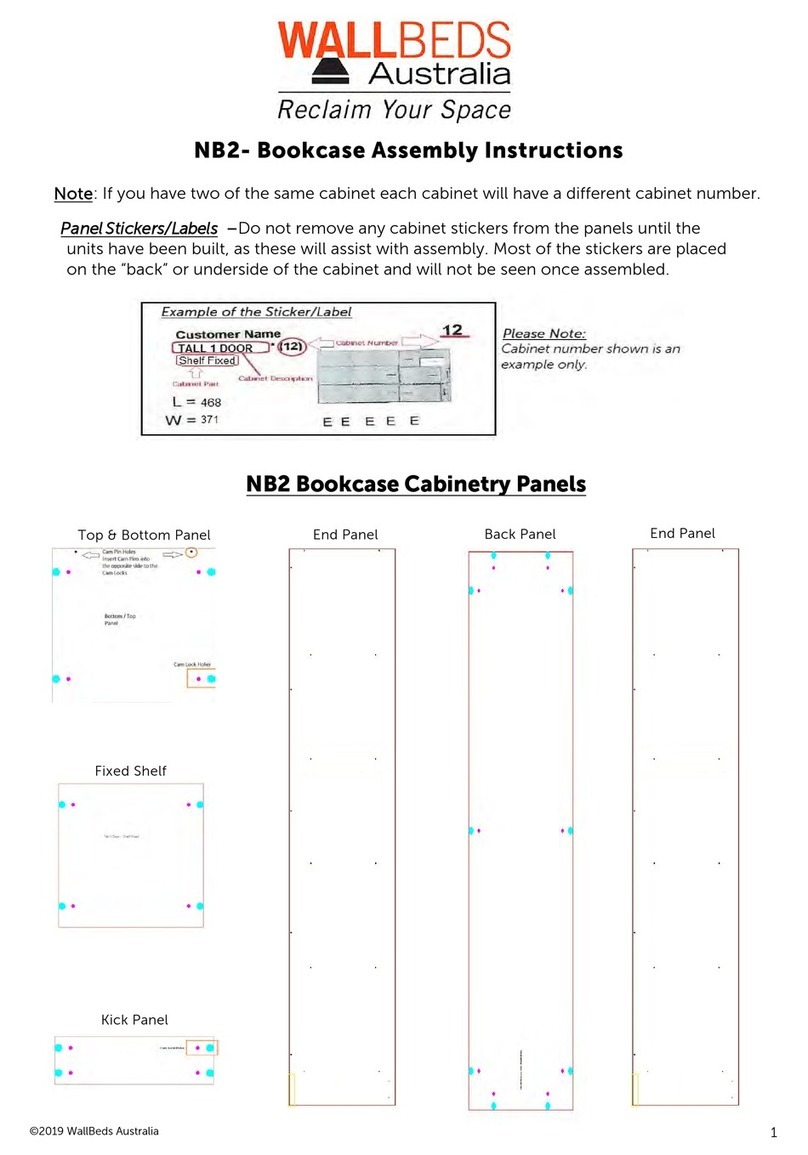
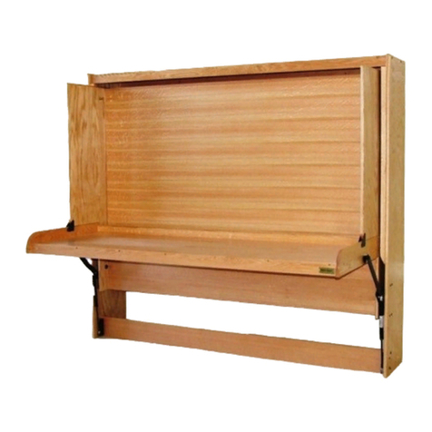
Wallbeds Alpha Bed Cabinetry Flat Pack User manual

1
Safety Advice Sheet PLEASE READ BEFORE YOU BEGIN:
° Please read and understand the instructions before assembly.
° Incorrect installation of this product could result inpersonal injury or
physical damage.
° WallBeds Australia recommends that eye protection is worn when
° assembling the product.
° WallBeds Australia recommends two people to assemble and install
the wall bed safely - It is not recommended you try to assemble this
wall bed on your own.
° The wall bed MUST be securely fastened to the wall. Failure to do so
will cause the wall bed to tip over & may cause damage to the cabinet
or serious personal injury.
° While these products are DIY, it is recommended a qualified
tradesperson installs the wall bed if you are not comfortablewith the
installation of this product.
WallBeds Australia is not responsible for any damages or injuries
incurred by the incorrect installation of this product.

Alpha Bed
Cabinetry Flat
Pack Assembly
Instructions
Universal Alpha Bed frame which can be mounted ineither
vertical or horizontally.
Alightweight, universal structural steel bed frame with double
overlap steel stiffeners completed with a fold-away leg system.
The frame is designed to exceed the strength of wood or
aluminium.The Alpha frame may beused inresidential and
commercial applications.
Designed to Exceed International ISO 9002
Standards for residential specifications
SAFETY WARNING
WallBeds are designed tobe operated by adults. Use by
children may result in injuries to the child or damage to the
wall bed ifthey are unable tocontrol the opening or closing of
the mechanism adequately. Warranties do not cover injuries or
damage under these circumstances.
While wall beds meet Australian Standards, adult use and
supervision ofthe wall bed is required at all times.
© 2010 Murphy WallBed Systems Inc.
2

3
Alpha Bed Project Start-Up
Install springs in Spring Lift Mechanisms as per spring application chart. – NOTE -The
SBLM comes with four springs preloaded per spring arm. This amount MAY NOT be the
correct amount for your wall bed size. Ensure you check page 8 of this manual for the
proper amount of springs.
Steps to Complete Project
° Carefully unpack all cabinetry from the transportation crate.
° Prepare all cabinet components by inserting either Cam Locks or CamPins.
°
° Attach the Spring Lift Mechanism to 2 x bedside panels.
° Assemble the Bed Cabinet.
° Attach Bed Cabinet to the wall.
° Assemble Steel Bed Frame
° Attach Steel Frame to the bed Face / Base Panels.
° Install the Face / Base Panel in Cabinet.
° Install Handles, Leg Assembly, Mechanism Covers, Mattress
Hint - Do not remove any parts identification stickers from the cabinetry panels until the units
have been built, as these will assist with assembly. Generally, these stickers are placed on the "back"
or side of the cabinet that will not be seen once assembled.
To remove the stickers - carefully heat up with a hair dryer, to remove any sticky
residue use Wax and Grease Remover. Avoid using razor blades as you may damage the cabinetry.
YouTube tutorials are available from *Murphy Bed wall bed systems for the spring and frame
assembly. Any cabinetry shown in these clips DO NOT relate to WallBeds Australia Cabinetry
assembly.
These clips are a visual guide on how to assemble and install the spring lift and steel frame
component of the wall bed which is universal worldwide.
° Items needed to complete your assembly and installation.

4
Alpha Bed Carton Contents
Each Steel Frame Carton contains one Single, Double, Queen or King Steel Bed Frame complete
with leg assembly, PS-1 Panel Savers and necessary hardware. SBLM Mechanism components
are in separate carton.
Note: If you are making a Horizontal Bed, you will require a longer Leg Connector Rod from your
supplier.
Qty.
Steel Frame Carton Items Comments
2
Frame End Sections
Identical Head & Foot
2
Frame Side Sections
Identical, Right or Left
3(5)
Stiffeners - Bed Face (King Size)
Space evenly between Frame Sides
2
Fold-away Legs
One Left - One Right
1
Leg Connector Rod
Stabilizes and Eases Leg Operation
Hardware Card #3
14
Bolt 10-24x1/2” (M6x12mm) Black
Bolt Frame corners
2
Bolt 10-24x1 1/4” (M6 x 32mm) Black
Bolt Leg Stop Foot corners
16
Nut 10-24 (M6) Nylock
Use with M6x12mm & 32mm
4
Angle 1”x1”x1 3/4” (25x25x44mm) Black
Use inside Frame corners
2
1/2”x3/4” (13x19mm) Round Black Cylinder
Use with #1213 as Leg Stop
Hardware Card #4
2
1 1/2”x5/16” (T1.5x40mm) Black Washer
Secure Leg inside Frame
2
1 1/2”x.765” (T2.5x40mm) Black Washer
Secure Leg inside Frame
2
1 1/2”x.765” (T2.5x40mm) Black Nylon Washer
Between Leg & outside of Frame
2
Nut 5/16” (M8) Black Nylock
Secure Leg inside Frame
2
Bolt 1/4”-20 Black Hex Head
Attach Leg to Leg Rod
2
Star Washer for #1210
Attach Leg to Leg Rod
Hardware Card #5
1
Nylon Web Strap with Buckle
Secure Mattress to Bed
2
2
3/4”x1/4” (T1.5x25mm) Washer
#8x5/8” (M4x15mm) Wood Screw
Secure Mattress Strap to Frame and Bed
/Face Panel under Mattress
Hardware Card #7 – DO NOT USE SEE ATTACHING FACE / BASE INSTRUCTIONS
110 #8x5/8” (M4x15mm) Wood Screw Attach Steel Bed Frame to Bed Face
Qty.
SBLM Mechanism Carton Items
Comments
2
Cover Springs
1
Attach to Right Side Panel
1
Attach to Left Side Panel
1
Install correct number in each Mechanism
1
Spring Plate Covers
Lift Mechanism - Right Side
Lift Mechanism - Left Side #1
Bags containing 9 Springs
13” Pipe
Used to set the Lift Mechanisms
Hardware Card #2
– IMPORTANT SEE ASSEMBLING CABINET INSTRUCTIONS
10
Cone Allen Bolts 5/16-18 x 1 1/4 (32mm)
To attach Lift Mechanisms to Side Panels
4
Hex Head Bolt 5/16-18 x 1”
Attach Mechanism to Frame Side section
2
Round Allen Head Bolt 5/16-18 x 1”
Position Mechanism Arm on Frame Side
16
Hex Head Nylock Nut
section Secure Bolts and Screws
1
Allen Wrench 5/16“
For Allen Head bolts
2
Black Wood Screws
For Attaching Spring Plate Covers

Tools Required List
Listed below are the tools that will be required to assemble your wall bed.
The long drill bit and long Phillips head bit should be a minimum of 130mm in length.
These are used for the fixing screws when attaching the steel frame to the wall bed
door panels.
5
Level
Rubber Mallet
Studfinder Long Drill Bit
Long Phillips Head
Screwdriver
Phillips Screw Driver
Tape Measure
8mm spanner
1/2" spanner x 2
7/16 spanner
5mm Allen key

6
Handle
8g 40mmScrews
WallBeds Australia Hardware and Panel List
Hardware Parts
Cam Lock Cam Pin Dome Head Screw "L" Wall Bracket
10g 50mm Wall Fixing Screw Handle Screw 25mm Cone Allen Bolt
Wall Bed Panel List
2 x Side Panel - A
40mm wood
Screw holes
Wall
Bed
Side
Panel
Cam Pin Holes
Counter sunk
Bolt Holes
for Spring Lift
Cam Lock Holes x 4
40mm Wood Screw Holes x 5
Cam Lock Holes x 4
Top - C
Top Back - D
Top Panel - C
Top Back - D

7
Face/Base - E
Face/Base - E
Handle Screw Holes
Kick - B
Head Board - F
Lower Back - D
Cam Lock Holes Kick Board - B
Cam Lock Holes x 4
Lower Back - D
Wall Bed Panel List

8
D.
E.
Alpha Wall Bed Cabinet Components
C.
D.
A.
F.
B.
Drawing 1
Front of WallBed
Cabinet Components Description
E.Face/Base Panels
A.Side Panels
C.
Top Panel
D.
Back Panels
B. Kick
F.Head Boar

9
Spring Application Chart
BED SIZE BED PANEL MATERIAL
MDF Board
Particle Board
Single 5 springs per side 4 springs per side
Double 6 springs per side 5 springs per side
Queen 7 springs per side 6 springs per side
King 8- 9 springs per side 8 springs per side
The Spring Guide is based onthe following mattress weight;
Single
- 24kg
Double
- 38kg
Queen
- 41kg
King
- 47kg
After
you have completed installing and checked the operation of your bed, you may
find it necessary to add or remove springs to achieve the correct lift
effort.
Note: Studio Desk-- An additional spring per side is required.
Horizontal Bed - One less spring per side is required.
There are nine locations for springs. If the bed requires an even number of springs, do not
use the centre hole (#5 from the top). If the bed requires an odd number of springs, start
with the centre hole (#5 from the top)
TIP: For ease ofattaching springs, start by unhooking any factory pre-loaded springs.
By
doing this, you will find the Tension Arm moves morefreely.
Start by adding springs
towards the top ofthe Tension Arm (Hole #1) Then add springs tolower section of the
Tension Arm (Hole#9)
Hook the springs, so the open ends are facing outward. You may have to pry up the
tension arm and slide the spring under and snap them into place in the proper hole.
Ensure you match the same numbered hole from the topon the opposite plate.
You should have an equal number of springs on each side of the centre hole.
Use the same number of springs and the same layout on both the left and right
mechanisms.
Spring Hole #1
Upturned Edge
of Mounting Plate
Centerline
Spring Hole #9
Tension Arm
Arm Bracket
Drawing 2

Assembling the Wall Bed Cabinet
For easier final wall mount you should assemble bed cabinet in the room where it will be used.
Step 1 – Springs
° Fit the correct amount of springs to both spring lift mechanisms as per the Spring
Application Guide.
Refer Page 9
Drawing 2
Step 2 - Hardware
° Locate & insert all Cam locks and Cam pins into the pre-drilled locations on all the
cabinet panels -
See cabinetry parts page 6 , 7
Step 3 – Cabinet Assembly
° Important - When attaching all the cabinetry panels ensure that all cam locks arefacing
up (
or the outside of the cabinet ceiling or wall
). Cam Locks should not be seen once the
cabinet has been assembled and stood upright.
It isrecommended you use a hand
Phillips screwdriver to tighten thecam locks to thecam pins, not a power tool.
° With the edge tape of the Side Panels facing to the ground and the Spring Lift
Mechanism Countersunk holes facing to the outside of the cabinet. Attach the 2 x Side
Panels - A - to the Top Panel- C -by placing the Cam Locks over the cam pins & then
tighten the Cam
° Top Back Panel - D– Attach to the Side Panels - A - then tighten the Cam locks
° Headboard -F Attach to the side panels. Start with the cam lock that is closest to the
bottom edge of the headboard placed over the cam pin that isfurthermost from the
back edge of the side panel. The headboard should be on an angle with the top edge
of the headboard almost flush with the back of the side panels.
° Kick panel - B – Attach to the Side Panels then tighten the Cam locks.
° Lower Back Panel - D – Attach to the Side Panels - A - then tighten the Cam
locks
° Ensure the back edges of the Top panel - C - and the Top Back - D - are aligned and
then insert the 40mm wood screws through the pre-drilled holes that are in the
Top Panel -C
Refer Cabinetry Parts page 6
° Using the 40mm wood screws, secure the Top Panel and Back Panels through the pre-
drilled holes not previously used for the cam pins in the Side Panels – A-.
Refer End Panel -
A- on the Wall Bed Panel list.
Step 4 –Attaching the Spring Lift Mechanism
° After the cabinet has been assembled and all 40mm wood screws have been inserted,
stand the cabinet upright and place against the wall.
° Using the 25mm Cone Allen Head bolts supplied in the extra hardware bag. In the first
three countersunk holes DO NOT use the 30mm manufacturer supplied bolts in this
location. These 30mm bolts are to be used for the back two countersunk holes only. Failure
to do this will result in the Tension Arm not loading correctly when that step is reached.
Tighten using the Nylock nuts (16) supplied in hardware card #2.
10

11
40x40
Angle
Left
End
Panel
Wall
Right
End
Panel
Attaching Wall Bed Cabinet to your wall
Alert: If the wall is not a wood stud wall, then you will need to use metal stud screws, toggle bolts or
concrete expansion bolts as necessary. THESE ARE NOT SUPPLIED. Only fixings suitable for a timber
stud are supplied.
° The cabinet must be secured to wall studs orother wall structural members using
40mm x 40mm L-Brackets & the 65mm timber stud fixing screws orsuitable
replacements ifnota timber stud.
° Placing the cabinet against the wall. Locate 3 studs orother wall frame members at
the level of the Top panel.
Refer to Drawing 3
° Using a spirit level ensure the cabinet is level. You may need to use "packers" to achieve
the cabinet being level.
° Measure diagonally to be sure the cabinet is square. The wall bed will not operate
correctly if the cabinet is not square.
° Once the cabinet issquare and level, use one 65mm wood screws in each ofthree
"L" brackets to attach to studs.
° Re-check the wall bed cabinet is square and level and then secure "L"-Brackets to the
Top panel (C) of the wall bed by using the Dome Head wood screws.
Drawing 3

Alpha Bed Steel Frame Assembly
The Alpha Frame is adaptable as vertical or horizontal bed. A leg extension bar is required for a
horizontal bed.
Hardware Card #3 is used for Steel Frame Assembly
FRAME ASSEMBLY
° Using the four small corner brackets and 14 of the M6x12mm bolts and M6 Nylock Nuts
completely assemble the Steel Bed Frame by joining the four rails together.
LEG STOP
° Using the 2 x M6x32mm bolts plus M6 Nylock Nut along with the 2 x 1/2” x 3/4” Round
Black Cylinders tocreate the Leg Stop. Place these two bolts at outer right and left
bottom holes at the foot of the bed frame.
Refer
Drawing 6 page 14
Note: The stiffener bars are shown in Drawing 4for reference only. These are not attached until
the Attach Face / Base step inthismanual.
Three steel stiffeners are provided for all beds (5for King). These notched stiffeners will be attached
to divide the Bed Face / Base length into four equal sections.
Vertical Frame Assembly
Drawing 4
Horizontal Frame Assembly
12

13
Attaching the Frame to Face / Base Panels
Note: When fixing the Steel Frame to the Face / Base Panels you must use the Dome Screws
supplied in the supplementary hardware bag by WallBeds Australia. DO NOT
USE CARD #7 Failure to do so will result in damage to the Face / Base Panels.
Step1
° The front of the Face / Base panels is universal. Carefully check the panels for any
imperfections. This will determine which side you will use as the Face. Place the panels
down on a non-scratch surface such as a carpet or a blanket.
° Place a small washer or 5c piece between the two door panels at each end to create
an equal gap between the door panels. Ensure you remove these once you have
secured the steel frame in place.
It isrecommended that you pre-drill the holes forall the steel frame fixing screws. This will
reduce the risk of any "bulging effect" of the timber through the Face / Base panel.
It is essential to have the Steel Frame centered on the Face / Base panels. Any error will be
noticed in the vertical sight lines and may interfere with the operation of the Face / Base.
Use caution not to damage bed Face / Base panels by putting screws in too far into the recessed
areas.
Step2:
° Position the Steel Bed Frame on the bed Face / Base panels with the Head Frame section
flush with the head end of the bed Face / Base Panels
Refer
Drawing 5 page 14.
Place
the Steel Bed Frame, so it is centered on the bed Face I Base Panels; you will have
approximately 25mm space from the edge of the bed steel frame to the Face / Base panel
edges.
Step 3:
° Once the frame is square on the Face / Base panels, attach two screws to each side of all
four corners.
° To ensure the Steel Bed Frame remains square, start fixing the frame to the Face / Base
panel at each corner first. It is then followed by the middle on both sides of the steel
frame.
° Remove the two spacers then continue to fix in all the Steel Bed Frame screws.
Step 4:
° Space the Stiffener Bars over the Face/Base panels. These notched stiffeners should be
located and attached to divide the Steel Bed Frame length into four equal sections.
Drawing
5 page 14
°
Horizontal beds
are supplied with an extra timber stiffener. The timber stiffener is
secured into place using the 28mm wood screws. Use the steel stiffeners as well, one next to
the wood stiffener and the other two equally spaced.
Step 6:
Attach the mattress Nylon Web Strap (
Hardware card #5) a
pproximately 457mm from
the foot of the bed. Use one of the existing frame holes & dome screws from the steel
frame.
° Attach the Panel Savers
( PS-1 )
are per instructions on page 20
°

14
Stiffener (2)
Stiffener (3)
Stiffener 4
Stiffener (5)
Centered on
Washer
2 Stiffeners (4,5)
Stiffener (1)
Frame
Head of Bed
Steel Bed Frame to Face / BasePanels
Vertical Frame Assembly Horizontal Frame Assembly
Head of Bed
Leg Stop
Foot of Bed
Leg Stop Leg Stop
Head of Bed
Frame flush with
Head of Face I Base
Panels
Drawing 5
Foot of
Bed
Leg Stop
Vertical KING Bed Stiffener Placement Only
Side View (do not install legs
at this time, it is shown for
reference only)
Bed Face I Base
Panel
Drawing 6
Floor
Frame flush with
Head of Face I
Base Panels
Stiffener
Stiffener
Stiffener
Additional
timber
Stiffener
Stiffener
Stiffener
Frame
Stiffener

Setting the Spring Lift Mechanism
WallBeds Australia recommends eye protection is worn while setting the Spring
Lift Mechanism
Note: Have a helper assist in the setting of the lift mechanism and loading of the bed Face / Base
panel. Do not reach behind the tension arm when you are doing the setting procedure. Ensure the
tube supplied is placed far enough onto the tension arm to prevent either the tube slipping off or
breaking.
° Place the PVC tube supplied over the Spring Lift Arm. Placing one foot against the
bottom front edge of the Side / End panel of the wall bed.
° Lever the tension arm downwards until you can set the silver arm lock to the round
lock tube (hole A)
see drawing 7
. This isthe position of the topcone bolt that was
used to attach the Spring Lift mechanism. This may also require the assistance of a
helper to achieve this step.
Tip: A longer pipe or similar could be used providing it is not fragile and of similar or
stronger construction. This will allow for extra leverage when engaging the Tension Arm.
Round Lock Tube (Hole “A”)
Bolt in Hole #3 in Steel
Frame drops into this slot
when loading Bed Face/
Base Panel.
Tension Arm
Bolt through Hole #2 to secure
Arm Lock
Round Lock Tube (Hole “A”)
Drawing 7 Notch to rest against Round
Allen head of Bolt in Hole #1
15

16
Installing the Face/Base Panel onto the Spring Lift
Hardware from Card #2 in the SBLM carton is used in these steps.
°
On theSteel Frame insert two 5/16” x 3/4”Hex Head Bolts from theoutside through Hole
#3
see drawing 8
put the 5/16” Nylock nuts onthese bolts only until the nut is flush with
thebolt end.
DO NOT TIGHTEN AT THIS STEP.
° Insert the two Round Allen Head Bolts from the outside of theFrame through Hole #1
see
drawing 8
use 5/16” Nylock nuts and securely tighten.
° Stand the Face / Base panel to a vertical position between the tension arms. Lift and tilt back
evenly until the two hex head bolts in Hole #3 on either side of the Steel Frame drop into
the notched end of Tension Arm
refer drawing 9 page
17.
When installing theFace / Base panel the bottom edge of the Face / Base panel must be placed OVER
and BEHIND the kick panel.
° Once the Bolts in Hole #3 are entirely seated in the bottom of the notch in both Tension Arms.
Lower the Face / Base until the Allen Head Bolts are seated into the lower notch
see drawing 9
Do not twist the Face/Base panel as it is being lowered as the Round Allen bolts will come unseated.
If this occurs, then you will need to lift the Face / Base back up and re-lower back into position.
° Gently lower the Face / Base downwards toinsert the two remaining 5/16” x 3/4” Head Bolts
in Hole #2on both sides
refer drawing 9 page 17.
You may need to tilt the panel downward to approximately 45 degrees to reveal the bolt holes. This
will also release the Arm Locks; you will hear a click as they disengage.
° Hold the Face/Base panel securely and tighten the 4 x bolts in Holes #2 and #3.
° Once all 4 Nylock nuts have been tightened gently close the Face / Base panel.
Do not let Face / Base slam shut as the bed cabinet may have moved out of square while loading
and the leg may strike on a top edge of an end panel on the wall bed unit.
IMPORTANT - The Face / Base will NOT stay in the open or the down position until the mattress
has been loaded onto the Face / Base panel. The weight of the mattress is needed to counterbalance
the Spring Lift Mechanism.
If the Face / Base panel is hitting the top on one side of the wall bed End Panel when closing, the
wall bed may be now out of square. To fix this, nudge the bottom of the End Panel that the door is
hitting on towards the opposite side. You will then see the gap of the Face / Base open and no longer
strike the End Panel.
Tip
:
Once the Face / Base panel no longer strikes on the End Panel and the gap on either outer edge
of the Face/Base panel is even. You can also secure the Lower Back Panel (D) to the wall studs; this
will prevent any further cabinet movement.

17
Side Panel
Face/Base Panel
Hex Head Bolt in Hole #3
Bolt Hole #
2
Round Allen Bolt in Hole #1
Bed Steel Panel Rail
Bolt Hole #3 seated in slot
Bolt Hole #2
Round Allen Bolt in Bolt Hole #1 Seated in
notch. Refer drawing 9
Drawing 9
Drawing 8

18
Install Handles, Legs, Mechanism Covers, &Mattress
° Install the door handles
° Install legs with the nylon washers on the inside and outside of the steel rails. Tighten
the nylon nut to have asmall amount of friction when legassembly isrotated from
the up tothe down position.
drawing 10
° Install leg connector rod between legs and secure with 1/4" x 1 1/4"Hex head bolts
and star washers
drawing 11
.Be sure they are securely tightened so as not to become
loose.
° Attach the powder coated spring mechanism covers that were inthe SBLM Carton in
place. - Secure these with #8x 1 1/4” black wood screws through the hole in each of
the cover plates hardware Card #2 . These screws will fix into the timber side panels of
the bed. These screws will attach into the timber of the side end panels of the bed.
Drawing 12& 1
3
° Install mattress and secure with previously installed straps.
Drawing 12 Drawing 13
Drawing 10
Nylon
Steel
Washer
Steel Washer
Frame
Nylock Nut Steel washer
Steel Leg
Connector
Rod
Rubber
Foot
1I4"-20 x 1
1I4" Bolt
Star
Washer
Steel
Leg
Drawing 11
Front
View

19
Assembly Images
Photo 1 Photo 2
Photo 3Photo 4
Photo 5

Fitting Instructions for the Alpha Bed Steel Frame PS-1 Panel Saver
What does the PS-1 Do?
The PS-1 can be fitted toprotect the upper back face of the door panel if the user forgets to lower the
legs to the ground when opening the wallbed. Significant damage can be caused tothe wall bed face
panels as it passes from the horizontal point andgoes to the floor. The PS-1will reduce damage to the
face panels but will notprotect against possible damage to the Spring Lifting Mechanism by
overstretching the springs.
The PS-1 is attached at the bed head of the bed, not at the foot end of the bed where the leg is
mounted.
There is no left or right - the unused holes are for the opposite side.
Insert the indent on the PS-1 into the large hole in the frame closets to the corner angle bracket.
Secure the PS-1 into position by using the two (M6x12mm) Black bolts that hold the frame corner
brackets. The remaining two smaller holes in the PS-1 are there, as they are reversible and
interchangeable with either side of the frame.
Repeat this step for the opposite side.
20
Table of contents
Other Wallbeds Indoor Furnishing manuals
Popular Indoor Furnishing manuals by other brands

Vivo
Vivo DESK-E1L94B instruction manual

John Lewis
John Lewis Darton Groove 810/80701 instructions

Royal garden
Royal garden WOODINGTON FRS80834-ST Use and care guide

DITALIA
DITALIA BB-115 Assembly manual

Amart Furniture
Amart Furniture PROMENADE 62064 Assembly instruction

Hailey Home
Hailey Home CT1238 Assembly instructions

Great Little Trading
Great Little Trading Carry Caddy manual

Walker Edison
Walker Edison W58FP2DHDHB manual

Serta
Serta 49347 Assembly instructions

Cooper Lighting
Cooper Lighting LV2060ISMulti-Lamp Luminaire LV2060IS Specification sheet

Seconique
Seconique REGENT Assembly instructions

KWC
KWC 12.241.171.000 Specification sheet