Walrus Pump TPR Series User manual

Vertical Multistage Centrifugal Pump
WALRUS PUMP CO., LTD.
TPR Series
User Manual
ISO 9001 Certified

~ 1 ~
EC Declaration of Conformity
Manufacturer:
Walrus Pump Co., Ltd.
Address:
No.83-14, Dapiantou, Sanzhi Dist., New Taipei City 252, Taiwan
Declare that the machinery described:
Name : Water Pump
Model : TPR Series
Conform to the following directive:
2006/42/EC—Machinery directive
2014/35/EU—Low voltage directive
2014/30/EU—EMC (Electromagnetic compatibility) directive
2009/125/EC— Ecodesign Directive
Refer to the following standards:
EN ISO 12100:2010 EN ISO 13857:2008
EN 809:1998+A1:2009 EN 60204-1:2006
EN 60335-1:2012 EN 60335-2-41:2003+A2:2012
EN 61000-6-2:2005 EN 61000-6-3:2007
R&D department manager: Kao Tien-chuan
Manager:

Please read this instruction manual carefully before installing your new system
as failures caused by incorrect installation and operation are not covered by
the warranty.
1. Handling the pump
When lifting the entire pump with motor, follow these instructions:
Lift the pump in the motor flange by means of straps or the like.
Fig. 1 Correct lifting of a TPR pump
2. Model explanation
Application
TPR, TPR_S and TPR_N pumps are suitable for liquid transfer, circulation and pressure
boosting of cold or hot clean liquids.
Use TPR_N pumps in systems where all parts in contact with the liquid are made of
high-grade stainless steel.
TPR 1 -4 -S F -RSSH
Pump
Dey to codes
Example
Code Description
Code for materials
S
N
SUS 304
SUS 316
Type range:
TPR
Flow rate
Number of impellers
Code for materials
Code for pipe connection
Code for shaft seal
Code for pipe connection
F
P
DIN Flange
PJE Coupling
Shaft seal
Example
Code Description
Shaft seal type designation
Material of stationaryr seal face
Material of otating seal face
Material of secondary seal (rubber part)
R S S H
E
H
EPDM
HNBR
Seal face material (stationary and rotating)
Secondary seal material (rubber parts)
R
Silicon Carbide (SIC)
S
~ 2 ~

3. Technical data
3.1 Operation condition
Delivery liquids : non-viscous, non-flammable/explosive, not containing solid or fiber
particles, and should not cause physical nor chemical damage to the pump. For viscosity
larger than water, use pumps with a higher output if necessary. Whether a pump is
suitable for a certain liquid depends on factors such as the liquid’s chlorine content, PH
value, temperature and composition, among other factors.
Liquid Temperature : -20°C~+120°C
Ambient Temperature : Max.+40°C
At ambient temperatures over 40°C or altitudes over 1000m above sea level, motor heat
dissipation will be reduced due to reduced air density. The power output will
also be reduced accordingly. In those situations, a higher rated pump is necessary.
3.2 Motor
The motor is a totally enclosed, fan cooled, 2-pole standard motor.
Installation specifications: 0.37-4.0kW, V18; over 5.5kW, V1
Insulation class: F
Enclosure class: IP 55 and IP 54
Stops and Restarts: 0.37 up to 4kw, 30 times / hour
Over 4.0kw, 20 times / hour
3.3 Operating range of the shaft seal
The operating range of the shaft seal depend on operating pressure, pump type, type of
shaft seal and liquid temperature. The range show in fig.2 applies to clean water with
anti-freeze liquids. If the operating range is exceeded, the life of the shaft seal may be
reduced.
~ 3 ~
-60 -40 -20 0 20 40 60 80 100 120 140
0
5
10
15
20
25
30
35
p [bar]
RSSE/V/H
RGSE/V
R
S
S
E
t [°C]
RSSH
RSSV
RSSE
Fig.2 Operating range of standard shaft range
Standard
Shaft seal
RSSH
RSSE
RSSV
RGSE
RGSV
SiC / SIC, HNBR
SiC / SIC, EPDM
SiC / SIC, VITON
Carbon / SIC, EPDM
Carbon / SIC VITON
0.37-18.5
0.37-18.5
0.37-18.5
0.37-18.5
0.37-18.5
-20~+120
-40~+120
-20~+120
0~+120
0~+120
Motor
Size
【kW】
Liquid
Temperature
【°C】
Description

3.4 Minimum Inlet Pressure, NPSH
Check the minimum inlet pressure under the following conditions:
•The liquid temperature is high
•Flow rate significantly larger than quoted maximum
•The fluid requires a long sucking distance
•Long pipes lead to the fluid inlet point
Use the formula below to calculate the maximum suction distance of the pump:
H = Pb x 10.2 – NPSH – Hf – Hv – Hs
Pb – Atmospheric pressure [bar]. In an enclosed system, Pb is the system pressure.
NPSH – Net Positive Suction Head [m]. Read from the NPSH curve, for the maximum
value of the particular pump system.
Hf = Loss from suction pipes [m], calculate from pump’s maximum flow values.
Hv = Vapor pressure [m], read from the vapor pressure chart.
Hs = Safety margin [m], use the minimum 0.5m if necessary.
If H is positive then the pump can safely operate at a maximum suction distance H. If H is
negative then an inlet pressure H must be guaranteed.
Example:
Pb =1bar
Pump type: TPR 3 , 60Hz
Flow rate: 3 m3/hr
NPSH: 1.7m
Hf = 3.0m
Liquid temperature: +40℃(From Fig.3)
Hv = 3.1m
H = 1 X 10.2 - 1.7 - 3.0 – 0.75 - 0.5 = 4.65m
This means that the pump can operate at a suction lift of maximum 4.25 meters head.
~ 4 ~
Fig.3 Minimum Inlet Pressure, NPSH

3.5 Maximum inlet pressure
The following table shows the maximum permissible inlet pressure. However, the actual
inlet pressure plus the pressure against a closed valve must always be lower than the
maximum permissible operating pressure.
If the maximum permissible operating pressure is exceeded, the conical bearing in the
motor may be damaged and the life of the shaft seal reduced. (see page 11)
3.6 Minimum flow rate
Due to the risk of overheating, do not use the pump at flows below the minimum flow rate.
The curves below show the minimum flow rate as a percentage of the nominal flow rate
in relation to the liquid temperature.
- - - - = air-cooled top.
~ 5 ~
Fig. 4 Minimum flow rate
Caution:The pump must not run against a closed discharge valve.

4. Installation
4.1 The pump must be secured to a horizontal, plane and solid foundation by bolts
through the holes in the base plate.
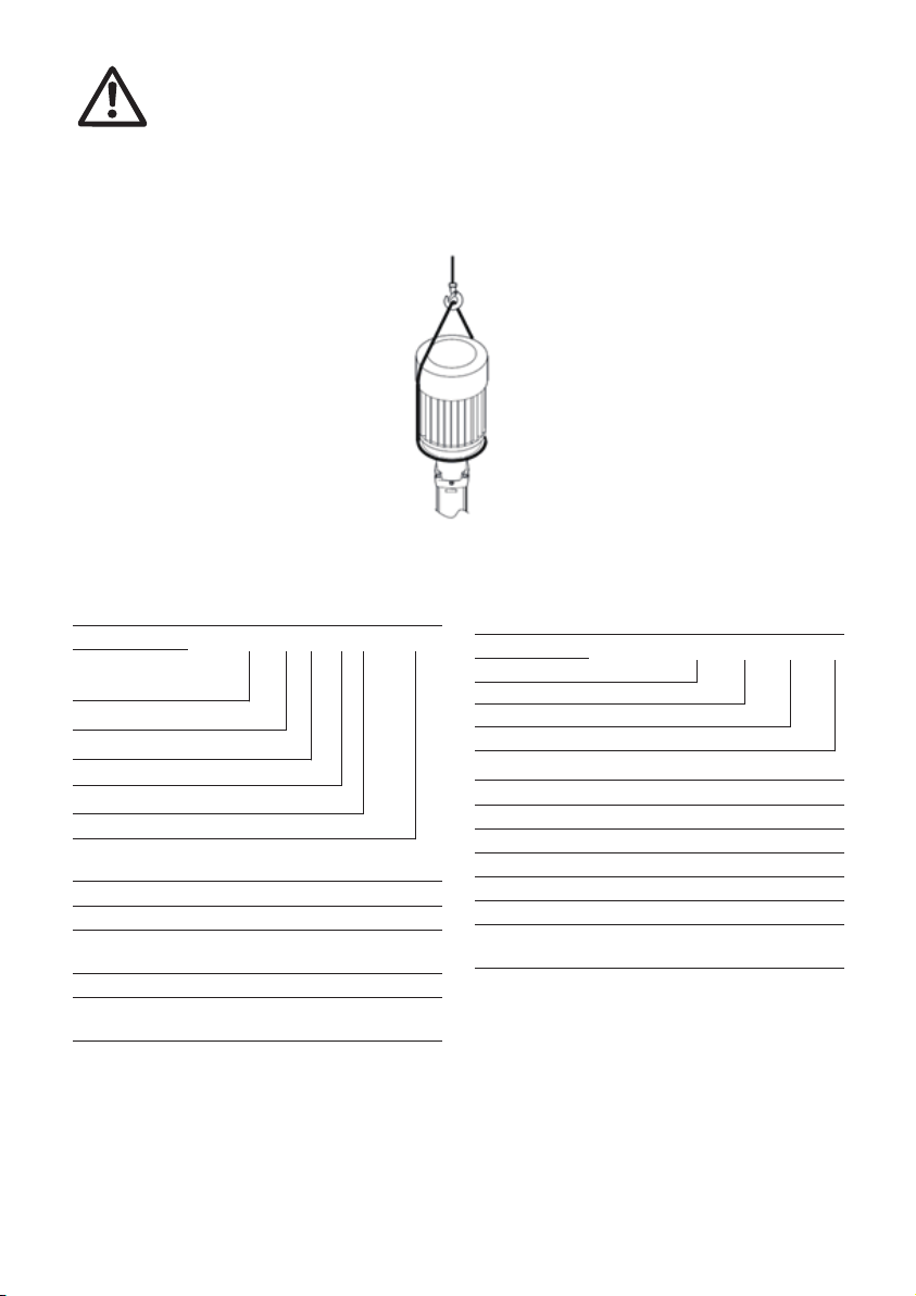
When installing the pump, follow the procedure below in order to avoid damaging the
pump.
4.2 Outdoor installation: When the pump is installed outside, please provide
a suitable cover to protect it from weather and forst. Please do not allow any
foreign objects fall into the motor fan cover.
~ 6 ~
Step Action
1.
2.
3.
4.
5.
6.
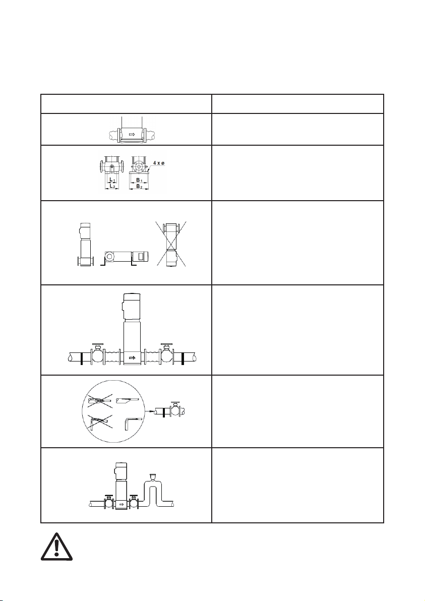
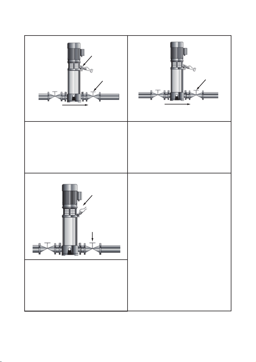
Arrows on the pump base show the
direction of flow of liquid through the pump.
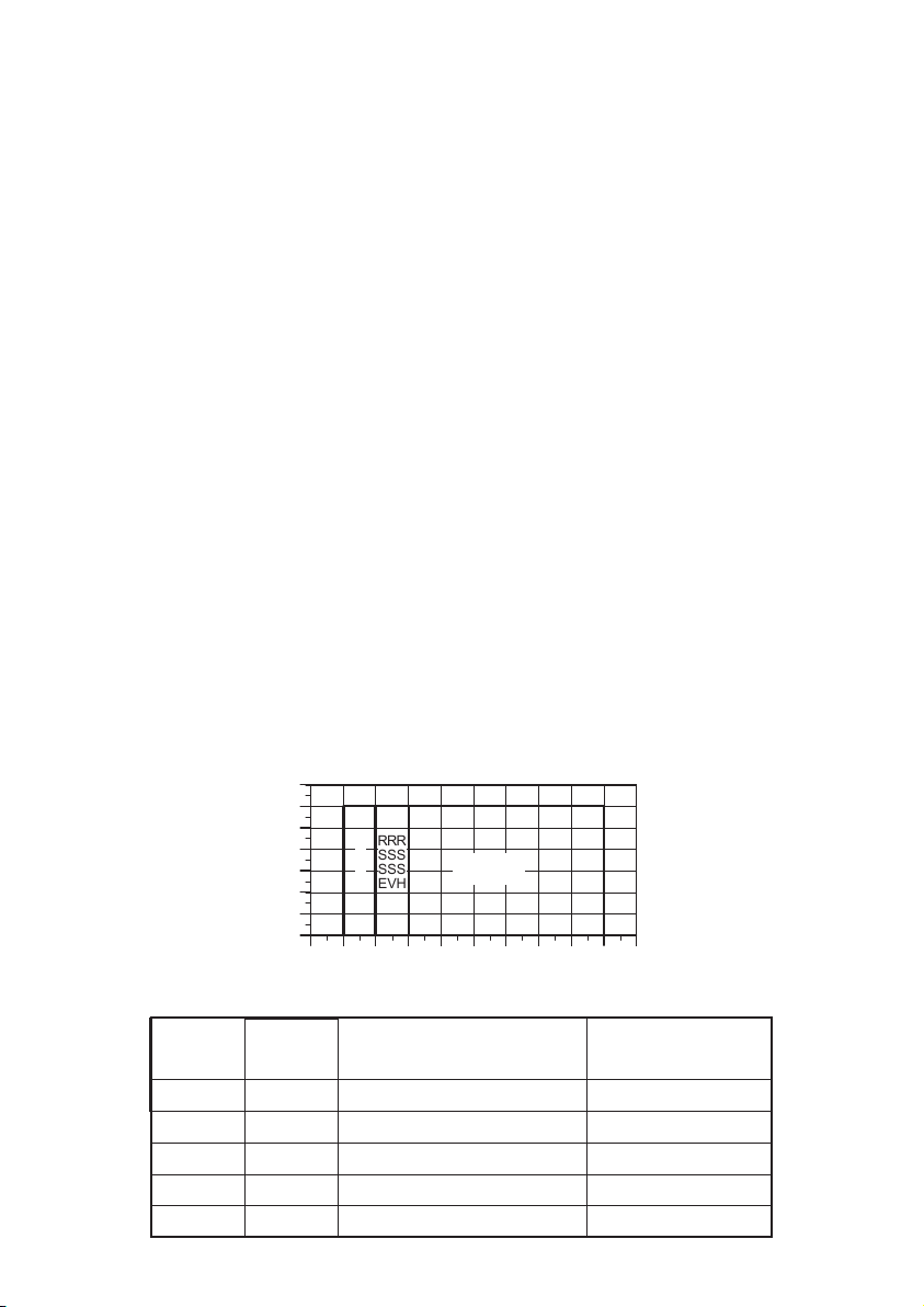
This information is in:
• port-to-port lengths
• dimensions of the base
• pipework connections
• diameter and position of foundation bolts.
The pump can be installed vertically or
horizontally (TPR, TPRN 120 and 150, 75
kW, only vertically). However, the motor must
neither fall below the horizontal plane nor be
installed upside down.
Ensure that an adequate supply of cool air
reaches the motor cooling fan.
Motors above 4 kW must be supported.
To minimize possible noise from the pump,
we advise you to fit expansion joints on either
side of the pump.
Fit isolating valves on either side of the pump
to avoid draining the system if the pump
needs to be removed for cleaning, repair or
replacement.
Always protect the pump against backflow by
means of a non-return valve (foot valve).
Install the pipes so that air locks do not
occur, especially on the suction side of the
pump.
Fit a vacuum valve close to the pump if the
installation has one of these characteristics:
• The discharge pipe slopes downwards
away from the pump.
• There is a risk of siphon effect.
• Protection against backflow of unclean
liquids is needed.

5. Electrical Connection
5.1 The electrical connections must be performed by a qualified electrician in
compliance with the required regulations.
5.2 Make sure that the supply voltages and frequencies matched with the
electric motor rating plate.
Provide suitable general protection against short circuits on the power line.
5.3 Before removing the terminal box cover and before any removal/dismantling of the
pump, make sure that the electricity supply has been switched off.
5.4 The power supply line must be provided with the following devices (unless otherwise
specified by the local regulations in force:
• A short-circuit protection device
• A high-sensitivity differential device providing additional protection against electric
shock in case the grounding system is inefficient.
• A mains isolator switch with a contact gap of at least 3 millimeters (⅛”).
5.5 The operating voltage and frequency are marked on the motor nameplate. Make sure
that the motor is suitable for the electricity supply on which it will be used.
5.6 Overload protection (single-phase motors)
The single-phase electric pump have an automatic reset protection incorporated in
the motor (thermal protector). Be careful because the pump could start up suddenly
once the motor winding has cooled down.
5.7 Overload protection (three-phase motors)
You must provide the overload protection (thermal relay or motor protector)
6. Start-up
6.1 Note: Do not start the pump until it has been filled with liquid and vented.
For priming, the pump and suction piping must be filled with liquid before
startup. If the pump runs dry, the pump bearings and the shaft seal may be
damaged.
6.2 Liquid level higher than the pump
Remove the fill/bleed plug and open the suction valve until the water flows out of the plug,
then re-tighten it (fig. 5).
Follow the instructions on page 7 and 8
~ 7 ~
Fig. 5 Location of drain plug and bypass valve

~ 8 ~
Start-up
open close
water flow
1. 2.
4.
3.
1. Close the isolating valve on the discharge
side of the pump and open the isolating
valve on the suction side.
3. See the correct direction of rotation of the
pump on the motor fan cover.
4. Start the pump and check the direction of
rotation.
2. Remove the priming plug from the pump
head and slowly fill the pump with liquid.
Replace the priming plug and tighten
securely.

~ 9 ~
water flow
open half
6.
water flow
open a little
open a little
5.
7.
lock
completely open
5. Vent the pump by means of the vent valve
in the pump head. At the same time, open
the discharge isolating valve a little.
7. Close the vent valve when a steady
stream of liquid runs out of it. Completely
open the discharge isolating valve.
6. Continue to vent the pump. At the same
time, open the discharge isolating valve a
little more.
8. For further information, see page 9.

~ 10 ~
7. Maintenance
Before starting work on the pump, make sure that all power supplies to the pump have
been switched off and that they cannot be accidentally switched on.
Pump bearings and shaft seal are maintenance-free.
Motor bearings
Motors not fitted with grease nipples are maintenance-free.
Motors fitted with grease nipples should be lubricated with a high temperature,
lithium-based grease. See the instructions on the fan cover.
In the case of seasonal operation (motor is idle for more than 6 months of the year), we
recommend you to grease the motor when the pump is taken out of operation.
8. Fault finding
Warning
Before removing the terminal box cover and before removing/dismantling
the pump, make sure that the power supply has been switched off and that
it cannot be accidentally switched on.
Fault
Motor does not
run when started.
Pump runs but
gives no water.
Pump
performance not
constant.
Cause
1. Supply failure.
2. Fuses are blown.
3. Motor-protective circuit breaker has
tripped out.
4. Thermal protection has tripped out.
5. Main contacts in motor-protective
circuit breaker are not making contact
or the coil is faulty.
6. Control circuit is defective.
7. Motor is defective.
1. Suction pipe/pump blocked by
impurities.
2. Foot or non-return valve blocked in
closed position.
3. Leakage in suction pipe.
4. Air in suction pipe or pump.
5. Motor runs in the wrong direction of
rotation.
1. Pump inlet pressure is too low
(cavitation).
2. Suction pipe/pump partly blocked by
impurities.
3. Pump draws in air.
Remedy
Connect the power supply.
Replace fuses.
Reactivate the
motor-protective circuit
breaker.
Reactivate the thermal
protection.
Replace contacts or magnetic
coil.
Replace the control circuit.
Replace the motor.
Clean the suction pipe/pump.
Repair the foot or non-return
valve.
Repair the suction pipe.
Check the suction conditions.
Chang the direction of
rotation of the motor.
Check the suction conditions.
Clean the suction pipe/pump.
Check the suction conditions.

9. Safety Protection
9.1 Frost Protection
Pumps that are not being used during periods of frost should be
drained to avoid damage.
9.2 Scald Protection
Do not touch the outer surface, when the pump is used for hot liquid
transmission.
10. Coupling adjustment
TPR1,3,5(S,N)
TPR10,15,20(S,N)
1. 2.
3. 4.
~ 11 ~
1. 2.
3.
Y
Y/2

~ 12 ~
Maximum inlet pressure for TPR, TPR_S and TPR_N
50Hz
1-2 → 1-36
3-2 → 3-29
3-31 → 3-36
5-2 → 5-16
5-18 → 5-36
10-1 → 10-6
10-7 → 10-22
15-1 → 15-3
15-4 → 15-17
20-1 → 20-3
20-4 → 20-17
32-1-1 → 32-4
32-5-2 → 32-10
32-11-2 → 32-14
45-1-1 → 45-2
45-3-2 → 45-5
45-6-2 → 45-13-2
64-1-1 → 64-2-2
64-2-1 → 64-4-2
64-4-1 → 64-8-1
90-1-1 → 90-1
90-2-2 → 90-3-2
90-3 → 90-6
60Hz
1-2 → 1-25
1-27
3-2 → 3-15
3-17 → 3-25
5-2 → 5-9
5-10 → 5-24
10-1 → 10-5
10-6 → 10-17
15-1 → 15-2
15-3 → 15-12
20-1
20-2 → 20-10
32-1-1 → 32-3
32-3-2 → 32-6
32-7-2 → 32-10-2
45-1-1 → 45-1
45-2-2 → 45-3
45-4-2 → 45-7
64-1-1
64-4 → 64-2-1
64-2 → 64-5-2
90-1-1 → 90-2-2
90-2-1 → 90-4-2
10bar
10bar
15bar
10bar
15bar
8bar
10bar
8bar
10bar
8bar
10bar
4bar
10bar
15bar
4bar
10bar
15bar
4bar
10bar
15bar
4bar
10bar
15bar
10bar
15bar
10bar
15bar
10bar
15bar
8bar
10bar
8bar
10bar
8bar
10bar
4bar
10bar
15bar
4bar
10bar
15bar
4bar
10bar
15bar
10bar
15bar


CC70D0022DA00EW0R02-03
WALRUS PUMP CO., LTD.
Web: www.walruspump.com
Table of contents
Other Walrus Pump Water Pump manuals
Popular Water Pump manuals by other brands

Alfalaval
Alfalaval CSI LKH UltraPure Series instruction manual

Versa-Matic
Versa-Matic E4 Series Service & operating manual

AME
AME 15924 Instruction manual & parts breakdown

SPX FLOW
SPX FLOW C Series instruction manual

Power Fist
Power Fist 8645830 user manual

SPX FLOW
SPX FLOW Universal 5000 Industrial Series instruction manual