5. Electrical Connection
5.1 The electrical connection
should be carried out in
accordance with local
regulations. Never make
any connections unless the
electricity supply has been
switched off.
5.2. The electrical hazard warn-
ing mark is placed outside
the connection box. Be
careful.
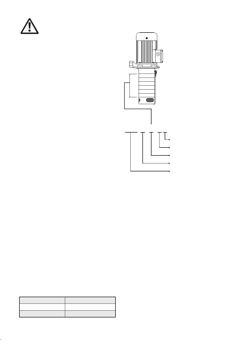
5.3. Electrical data (voltage and frequency)
are shown on the pump nameplate.
Verify if these data match your electric-
ity supply. A circuit breaker should be
installed and the grounding be proper-
ly connected for your safety.
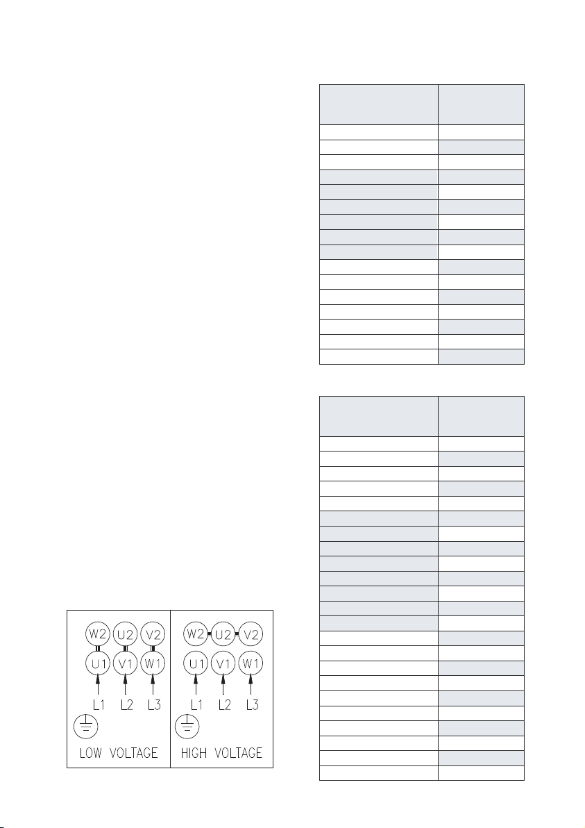
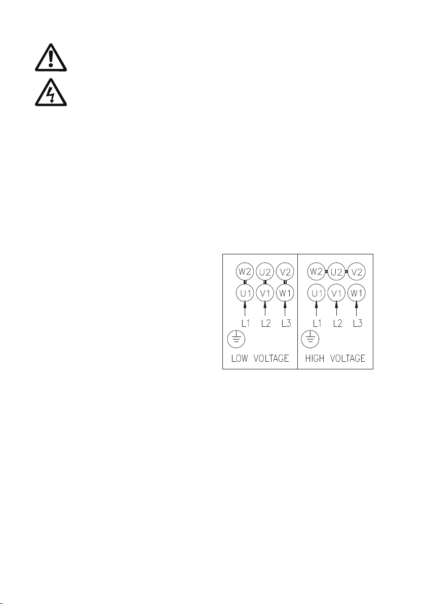
5.4. Make electrical connection in accor-
dance with connecting diagram
located inside the connection box. The
motor current must be within the rated
amps range indicated on nameplate.
Three phase motor requires a magnet-
ic starter for safety.
5.5. For three phase motors, please check
the correct direction of rotation of the
pump on the motor fan cover. When
seen from motor fan cover end, the
pump should rotate clockwise. You
can reverse the direction of rotation by
interchanging any two of the incoming
supply wires.
6. Start-up
Before starting the pump, make sure the
following:
6.1. For three phase motors, verify if the
rotating direction is correct. It should
be clockwise viewing from the motor
fan cover end.
6.2. All piping joints are completely tight.
Leakage in piping may cause the
pump hydraulic loss.
6.3. The pump is filled with liquid.
6.4. The suction filter is not blocked by any
foreign objects.
7. Operation and Maintenance
It is dangerous to operate the
pump against a closed
discharge outlet because it will
cause extremely high liquid flow
temperature and damage the
pump in a few minutes.
7.1. Lubrication
The mechanical seal and shaft
sleeves are lubricated by the pumped
liquid.
~ 3 ~
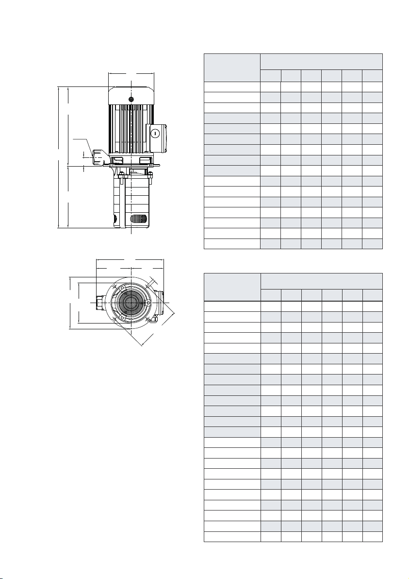
4. Installation
The pump has hot surface on
the motor. It must be installed so
that persons cannot accidental-
ly come into contact the hot
surface.
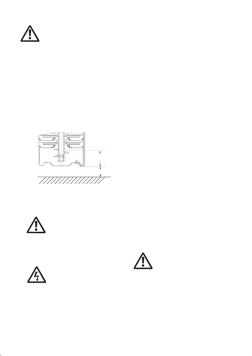
4.1. Submerged Depth
To avoid dry running and damage the
pump during operation, the minimum
pump submerged depth is 40mm (15
/
8
”) as shown in Fig 1. In addition, the
bottom of the pump suction inlet must
be at least 25 mm (1”) above the
bottom of the tank.
Fig.1
Min. 40 mm
25 mm