Walrus Pump TPU Series User manual

Self-prime Pump
Model : 1100 / 1500
To ensure safe and proper use, please read this instruction before operation.
ISO 9001 Certified
TPU Series
Instruction Manual
Walrus America Inc.

6. Start-Up
Before starting the pump, make sure
the following:
6.1 For three phase motors, verify if
the rotating direction is correct. It
should be clockwise viewing from
the motor fan cover end.
6.2 All piping joints are completely
tight. Leakage in piping may cause
the pump hydraulic loss.
6.3 The pump is filled with liquid.
6.4 The suction filter is not blocked by
any foreign objects.
7. Operation and Maintenance
It is dangerous to operate
the pump against a closed
discharge outlet because it
will cause extre-mely high
liquid flow temperature and
damage the pump in 20
minutes.
7.1 Lubrication
The pumped liquid lubricates the
mechanical seal and shaft
sleeves.
7.2 Suction Filter
Always keep suction filter clean
and make sure it is not blocked by
impurities.
7.3 Periodic Checks
To ensure regular operation,
please follow the below-checking
points:
7.3.1. Check the amount of liquid
and operating pressure.
7.3.2. Check there are no leaks on
piping joints.
7.3.3. Check the tripping of the
motor starter.
7.3.4. Check that all controls are
functioning normally.
~ 1 ~
TPU Instruction Manual
Before installing your new
system, please study all
instructions carefully, as the
warranty does not cover
failures caused by incorrect
installation and operation.
1. Application
1.1 The TPU Series is single-stage
centrifugal pump designed for
farm or fishery use.
1.2The pump can not be used to trans-
fer explosive liquids, such as gaso-
line, diesel oil or similar liquids. It
is suitable to carry liquids such as
water, coolant, low viscosity or
other non-corrosive liquids.
2. Product Code Designation
The pump is named by motor’s output
power. There are numbers in name-
plate.
3. Operating Limits
1. Ambient Temperature: Max. +40℃
2. Liquid Temperature range: +4℃~
+40℃
3. Enclosure Class: IP54
4. Operating pressure: Max. 3kg/cm²
5. Inlet Pressure: 0 kg/cm²
6. Kinematical Viscosity: 1 cst
(mm²/s)
7. Max. Suction depth: 6m
8.Stop and Restarts:
5.4 For your safety, please make sure
that the wiring is correctly ground-
ed.
5.5 To avoid the possibility of dry
running, we strongly recommend
installing dry running protection.
5.6 The pumps must be supplied
through a Residual Current Device
(RCD) with a rated residual operat-
ing current not exceeding 30 mA.
5.7 If the supply cord is damaged, it
must be replaced by the manufac-
turer, authorized service agent, or
qualified persons in order to avoid
causing a hazard.
5.8 This pump appliance is not intend-
ed for use by persons (including
children) with reduced physical,
sensory or mental capabilities or
lack of experience and knowledge
unless they have been given super-
vision or instruction concerning
use of the pump appliance by a
person responsible for their
safety.
5.9 Make electrical connection in
accordance with connecting
diagram located inside the
connection box. The motor current
must be within the rated amps
range indicated on nameplate.
Three phase motor requires a
magnetic starter for safety.
5.10 For three phase motors, please
check the correct direction of
rotation of the pump on the motor
fan cover. When seen from motor
fan cover end, the pump should
rotate clockwise.You can reverse
the direction of rotation by inter-
changing any two of the incoming
supply wires.
Output power[kW] times/hour
Below 2.2 250
TPU 1100
Output Power
Model Type
4. Installation
The pump has hot surface
on the motor. It must be
installed so that persons
cannot accidentally come
into contact the hot surface.
4.1 We recommend outlet and inlet
should stay the same size as the
original. If you marrow the pipe
size, it will affect the performance
of the pump.
4.2 For convenient replace or mainte-
nance, the outlet side must be
installation valve and union, and
the inlet side should install union
too.
4.3 Please shorten the pipe as possi-
ble as well, so that reduce leakage.
4.4 Please install filter at inlet, if there
is easily inhale Impurities.
4.5 Install the pump in a well-ventilat-
ed and well-drained place.
5. Electrical Connection
5.1 The electrical connection
should be carried out in
accordance with local
regulations. Never make
any connections unless
the electricity supply has
been switched off.
5.2 The electrical hazard
warning mark is placed
outside the connection
box. Be careful.
5.3 The electrical connection should
be carried out in accordance with
local regulations. The operating
voltage and frequency are marked
on the nameplate. Please make
sure that these data match your
job requirement.
7.4 When pump is not in use for a
period, it should be drained. For
start up after long time inactivity
please check if the impeller and
mechanical seal are free. If they
are locked up by sand, rust or
something else please clean them
up.
7.5 DO NOT use the pump should not
be used to transfer toxic or
contaminated liquids. Please
carefully follow all instructions in
the manual as Walrus may refuse
to accept the contaminated pump
for servicing.
7.6 If the power supply cord is dam-
aged, it must be replaced by an
authorized engineer or assembly
available from the manufacturer or
service agent.
8. Noise Level

6. Start-Up
Before starting the pump, make sure
the following:
6.1 For three phase motors, verify if
the rotating direction is correct. It
should be clockwise viewing from
the motor fan cover end.
6.2 All piping joints are completely
tight. Leakage in piping may cause
the pump hydraulic loss.
6.3 The pump is filled with liquid.
6.4 The suction filter is not blocked by
any foreign objects.
7. Operation and Maintenance
It is dangerous to operate
the pump against a closed
discharge outlet because it
will cause extre-mely high
liquid flow temperature and
damage the pump in 20
minutes.
7.1 Lubrication
The pumped liquid lubricates the
mechanical seal and shaft
sleeves.
7.2 Suction Filter
Always keep suction filter clean
and make sure it is not blocked by
impurities.
7.3 Periodic Checks
To ensure regular operation,
please follow the below-checking
points:
7.3.1. Check the amount of liquid
and operating pressure.
7.3.2. Check there are no leaks on
piping joints.
7.3.3. Check the tripping of the
motor starter.
7.3.4. Check that all controls are
functioning normally.
~ 2 ~
TPU Instruction Manual
Before installing your new
system, please study all
instructions carefully, as the
warranty does not cover
failures caused by incorrect
installation and operation.
1. Application
1.1 The TPU Series is single-stage
centrifugal pump designed for
farm or fishery use.
1.2The pump can not be used to trans-
fer explosive liquids, such as gaso-
line, diesel oil or similar liquids. It
is suitable to carry liquids such as
water, coolant, low viscosity or
other non-corrosive liquids.
2. Product Code Designation
The pump is named by motor’s output
power. There are numbers in name-
plate.
3. Operating Limits
1. Ambient Temperature: Max. +40℃
2. Liquid Temperature range: +4℃~
+40℃
3. Enclosure Class: IP54
4. Operating pressure: Max. 3kg/cm²
5. Inlet Pressure: 0 kg/cm²
6. Kinematical Viscosity: 1 cst
(mm²/s)
7. Max. Suction depth: 6m
8.Stop and Restarts:
5.4 For your safety, please make sure
that the wiring is correctly ground-
ed.
5.5 To avoid the possibility of dry
running, we strongly recommend
installing dry running protection.
5.6 The pumps must be supplied
through a Residual Current Device
(RCD) with a rated residual operat-
ing current not exceeding 30 mA.
5.7 If the supply cord is damaged, it
must be replaced by the manufac-
turer, authorized service agent, or
qualified persons in order to avoid
causing a hazard.
5.8 This pump appliance is not intend-
ed for use by persons (including
children) with reduced physical,
sensory or mental capabilities or
lack of experience and knowledge
unless they have been given super-
vision or instruction concerning
use of the pump appliance by a
person responsible for their
safety.
5.9 Make electrical connection in
accordance with connecting
diagram located inside the
connection box. The motor current
must be within the rated amps
range indicated on nameplate.
Three phase motor requires a
magnetic starter for safety.
5.10 For three phase motors, please
check the correct direction of
rotation of the pump on the motor
fan cover. When seen from motor
fan cover end, the pump should
rotate clockwise.You can reverse
the direction of rotation by inter-
changing any two of the incoming
supply wires.
4. Installation
The pump has hot surface
on the motor. It must be
installed so that persons
cannot accidentally come
into contact the hot surface.
4.1 We recommend outlet and inlet
should stay the same size as the
original. If you marrow the pipe
size, it will affect the performance
of the pump.
4.2 For convenient replace or mainte-
nance, the outlet side must be
installation valve and union, and
the inlet side should install union
too.
4.3 Please shorten the pipe as possi-
ble as well, so that reduce leakage.
4.4 Please install filter at inlet, if there
is easily inhale Impurities.
4.5 Install the pump in a well-ventilat-
ed and well-drained place.
5. Electrical Connection
5.1 The electrical connection
should be carried out in
accordance with local
regulations. Never make
any connections unless
the electricity supply has
been switched off.
5.2 The electrical hazard
warning mark is placed
outside the connection
box. Be careful.
5.3 The electrical connection should
be carried out in accordance with
local regulations. The operating
voltage and frequency are marked
on the nameplate. Please make
sure that these data match your
job requirement.
7.4 When pump is not in use for a
period, it should be drained. For
start up after long time inactivity
please check if the impeller and
mechanical seal are free. If they
are locked up by sand, rust or
something else please clean them
up.
7.5 DO NOT use the pump should not
be used to transfer toxic or
contaminated liquids. Please
carefully follow all instructions in
the manual as Walrus may refuse
to accept the contaminated pump
for servicing.
7.6 If the power supply cord is dam-
aged, it must be replaced by an
authorized engineer or assembly
available from the manufacturer or
service agent.
8. Noise Level

~ 3 ~
6. Start-Up
Before starting the pump, make sure
the following:
6.1 For three phase motors, verify if
the rotating direction is correct. It
should be clockwise viewing from
the motor fan cover end.
6.2 All piping joints are completely
tight. Leakage in piping may cause
the pump hydraulic loss.
6.3 The pump is filled with liquid.
6.4 The suction filter is not blocked by
any foreign objects.
7. Operation and Maintenance
It is dangerous to operate
the pump against a closed
discharge outlet because it
will cause extre-mely high
liquid flow temperature and
damage the pump in 20
minutes.
7.1 Lubrication
The pumped liquid lubricates the
mechanical seal and shaft
sleeves.
7.2 Suction Filter
Always keep suction filter clean
and make sure it is not blocked by
impurities.
7.3 Periodic Checks
To ensure regular operation,
please follow the below-checking
points:
7.3.1. Check the amount of liquid
and operating pressure.
7.3.2. Check there are no leaks on
piping joints.
7.3.3. Check the tripping of the
motor starter.
7.3.4. Check that all controls are
functioning normally.
TPU Instruction Manual
Before installing your new
system, please study all
instructions carefully, as the
warranty does not cover
failures caused by incorrect
installation and operation.
1. Application
1.1 The TPU Series is single-stage
centrifugal pump designed for
farm or fishery use.
1.2The pump can not be used to trans-
fer explosive liquids, such as gaso-
line, diesel oil or similar liquids. It
is suitable to carry liquids such as
water, coolant, low viscosity or
other non-corrosive liquids.
2. Product Code Designation
The pump is named by motor’s output
power. There are numbers in name-
plate.
3. Operating Limits
1. Ambient Temperature: Max. +40℃
2. Liquid Temperature range: +4℃~
+40℃
3. Enclosure Class: IP54
4. Operating pressure: Max. 3kg/cm²
5. Inlet Pressure: 0 kg/cm²
6. Kinematical Viscosity: 1 cst
(mm²/s)
7. Max. Suction depth: 6m
8.Stop and Restarts:
5.4 For your safety, please make sure
that the wiring is correctly ground-
ed.
5.5 To avoid the possibility of dry
running, we strongly recommend
installing dry running protection.
5.6 The pumps must be supplied
through a Residual Current Device
(RCD) with a rated residual operat-
ing current not exceeding 30 mA.
5.7 If the supply cord is damaged, it
must be replaced by the manufac-
turer, authorized service agent, or
qualified persons in order to avoid
causing a hazard.
5.8 This pump appliance is not intend-
ed for use by persons (including
children) with reduced physical,
sensory or mental capabilities or
lack of experience and knowledge
unless they have been given super-
vision or instruction concerning
use of the pump appliance by a
person responsible for their
safety.
5.9 Make electrical connection in
accordance with connecting
diagram located inside the
connection box. The motor current
must be within the rated amps
range indicated on nameplate.
Three phase motor requires a
magnetic starter for safety.
5.10 For three phase motors, please
check the correct direction of
rotation of the pump on the motor
fan cover. When seen from motor
fan cover end, the pump should
rotate clockwise.You can reverse
the direction of rotation by inter-
changing any two of the incoming
supply wires.
4. Installation
The pump has hot surface
on the motor. It must be
installed so that persons
cannot accidentally come
into contact the hot surface.
4.1 We recommend outlet and inlet
should stay the same size as the
original. If you marrow the pipe
size, it will affect the performance
of the pump.
4.2 For convenient replace or mainte-
nance, the outlet side must be
installation valve and union, and
the inlet side should install union
too.
4.3 Please shorten the pipe as possi-
ble as well, so that reduce leakage.
4.4 Please install filter at inlet, if there
is easily inhale Impurities.
4.5 Install the pump in a well-ventilat-
ed and well-drained place.
5. Electrical Connection
5.1 The electrical connection
should be carried out in
accordance with local
regulations. Never make
any connections unless
the electricity supply has
been switched off.
5.2 The electrical hazard
warning mark is placed
outside the connection
box. Be careful.
5.3 The electrical connection should
be carried out in accordance with
local regulations. The operating
voltage and frequency are marked
on the nameplate. Please make
sure that these data match your
job requirement.
The above drawing shows the noise
level while the pump operated with a
closed outlet.
The tolerance of noise level is ±3dB(A).
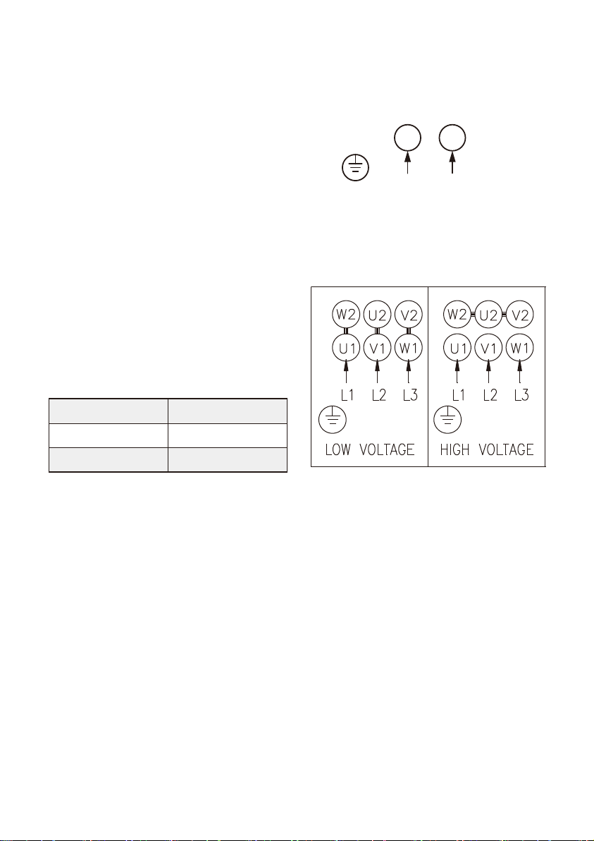
9. Wiring Diagram
Three Phase
Single Phase
200-240V
U1 V1
Motor dB(A)
TPU1100
TPU1500
75
78
7.4 When pump is not in use for a
period, it should be drained. For
start up after long time inactivity
please check if the impeller and
mechanical seal are free. If they
are locked up by sand, rust or
something else please clean them
up.
7.5 DO NOT use the pump should not
be used to transfer toxic or
contaminated liquids. Please
carefully follow all instructions in
the manual as Walrus may refuse
to accept the contaminated pump
for servicing.
7.6 If the power supply cord is dam-
aged, it must be replaced by an
authorized engineer or assembly
available from the manufacturer or
service agent.
8. Noise Level

~ 4 ~
10. Fault Finding
Make sure to disconnect the power before attempting to diagnose any fault.
Fault Cause Remedy
1. Motor does not run
start. Supply failure. Connect the electricity supply.
Fuses are blown. Replace fuses.
Motor starter overload has
tripped out. Reactivate the motor protection.
Thermal protection has tripped
out. Reactivate the thermal protection.
Main contacts in motor starter
are not making contact or the
coil is faulty.
Replace contacts or magnetic coil.
Control circuit is defective. Repair the control circuit.
Motor is defective. Replace the motor.
2. Motor starter
overload trips out
immedia tely when
supply is switched on.
One fuse / automatic circuit
breaker is blown. Cut in the fuse.
Contacts in motor starter
overload are faulty. Replace motor starter contacts.
Cable connection is loose or
faulty. Fasten or replace the cable
connection.
Motor winding is defective. Replace the motor.
Pump mechanically blocked. Remove the mechanical blocking
of the pump.
Overload setting is too low. Set the motor starter correctly.
One fuse / automatic circuit
breaker is blown. Cut in the fuse.
3. Motor starter
overload trips out
occasionally.
Overload setting is too low. Set the motor starter correctly.
Low voltage at peak times. Check the electricity supply.
4. Motor starter has not
tripped out but the
pump
does not run.
Supply failure. Connect the electricity supply.
Fuses are blown. Replace fuses.
Thermal protection has
tripped out. Reactivate the thermal protection.
Main contacts in motor starter
are not making contact or the
coil is faulty.
Replace contacts or magnetic coil.
5. Pump runs but gives
no liquid or pump
capacity is not constant.
Liquid level in tank too low. Increase the liquid level.
Pump draws in air. Check the suction conditions.
6. Leakage in shaft seal. Shaft seal is defective. Replace the shaft seal.
7. Noise. Cavitation occurs in the pump. Check the suction conditions.
Pump does not rotate freely
(frictional resistance) because of
incorrect pump shaft position.
Adjust the pump shaft.

~ 5 ~
11. Dimensions
12. Performance
TPU 1100 / 1500
Rp 2”
(348)
Rp 2”
Model
Max. pumping depth
Max head (m)
Max flow (L/min)
Pole
Output power (P2)
Inlet / Outlet
TPU 1100
6 m
23 m
490
6 m
28 m
510
2 pole
1.1 kW
Rp 2”
1.5 kW
Rp 2”
TPU 1500


Walrus America Inc.
walrusamerica.com
CC70D0031DA00UW0R00
This manual suits for next models
1
Table of contents
Other Walrus Pump Water Pump manuals
Popular Water Pump manuals by other brands

Wilo
Wilo Wilo-CronoLine-IL-E Installation and operating instructions

Blue Angel Pumps
Blue Angel Pumps Professional BSP45 Operating instructions and parts manual

Bijur Delimon
Bijur Delimon FZ-A Operation manual

Wilo
Wilo Wilo-Drain STS 40 Series Installation and operating instructions

Regulus
Regulus CSE OTS MFB+ZV G Installation and operation manual

Pentair
Pentair STA-RITE DS2 Series Installation and operation manual