Walton WF-HP-226 User manual

Sample specifications for WF-HP-226
Cold water centrifugal atomizing type humidifier and mounting
brackets for installation
in
duct systems negative or positive
pressure. Maximum allowed positive static pressure -.25" H2
0.
Water reservoir includes float valve to automatically regulate
water level. Humidifier includes motor, impeller, disk and
breaker comb to produce a fine vapor. Rotating parts shall be
electronically balanced to eliminate vibration. Tubes shall
be
employed to direct moisture into vertical or horizontal duct
systems and equalize humidifier internal air pressure to that
of
the duct. All water exposed parts to be copper, brass, or non-
ferrous alloy. Vapor output
of
the humidifier shall
be
constant
while
in
operation and shall not depend
on
the temperature
of
the air or water. Humidifier(s) shall
be
Model WF-HP-226 as
manufactured by Humidity source. Must
be
UL listed for US and
Canada.
-
SPECIFICATIONS
CAPACITY
Moisture Output - 3 Ib'/hr.
WEIGHT
Net: 17
lb.
Shipping: 19
lb.
Operating: 20
lb.
WATER CONNECTIONS &PRESSURES
Supply: 1/8" Male Pipe Thread
Overflow:
%"
Female Pipe Thread
Operating Pressure Range: 1
0-1
00 psig
Disk
Vapor Making
7+---
Comb
Pump Tube
Impeller
Cap
Electric Motor
50 Watts
115 volts, single phase, 60
Hz.
CARTON SIZE
15
Yz"
X 12
%"
X 15
%"
UNIT SIZE
Height:
11
Yz"
Diameter: 10
%"
CENTruFUGALATOM~ER
The heart of Humidity Source humidifier units
is
the patented
masterfully engineered Centrifugal Atomizer. Water is drawn
by centrifugal force up through the rotating impeller cap and
pump tube, then spun across the disk rotating at 3250 RPM
striking the Vapor-Maker Comb creating an extremely fine
vapor. An integral fan under the rotating disk blows the
vapor out
of
the unit resulting
in
a fine atomized vapor that
is
quickly absorbed into the air.

A
Humidity Source POSITIVE CAPACITY ATOMIZING humidifiers produce
moisture that will quickly
be
absorbed
in
to the air stream, provided there is
no
impingement. It
is
therefore most important that all directions and minimum dimensions
be
strictly adhered to
in
order to avoid condensation.
12'Minimum
Top View
-I
6'0'
Minimum
27/16"
1.0.
I
-~
_f
~
13112"
Water
Supply
Side View
Discharge Tube
/"
11------;
~-+--11
314"
-------Is
I\
Air
Intake
Overflow Mounting
Bracket
Duct Location Requirements
C
12'Minimum
__
6'0'
Minimum-
12'Minimum
ACCESSORIES
A. Duct mounted, high:limit humidistat.
Model No. HC-2011
B. Wall mounted humidistat. Model No.
P825.
C. Johnston Controls electronic humidistat.
Model No. W351 with remote sensor (E)
D. Air duct pressure switch. Model No.
PC-301 !

NOTE: MAXIMUM STATIC AIR PRESSURE
ALLOWED AT SUPPLY
IS
.25" H2
0.
1.
Choose a mounting location, with a 6
ft.
minimum straight
unobstructed downstream run, on the side
of
a
12
inch
minimum width
by
12
inch minimum height supply or return
duct. See Fig.
F.
2.
Place the mounting plate against the duct at the mounting
location and scribe the
(2)
large air tube holes and (11)
mounting screw locations on the duct.
3.
With a straight edge scribe a 3 inch wide
by
8 inch high
rectangle enclosing the
(2)
large circles
on
the duct and cut
out this rectangle.
4.
Drill
(2)
9/32
inch diameter holes at the two top screw hole
locations and drill the remaining
(9)
screw hole locations with
a #30 drill.
5.
Assemble the mounting plate to the duct with (2)
Y.
-20
screws and nuts and
(9)
#10 sheet metal screws.
6.
Slide the intake tube with a tube seal onto the reservoir air
intake tube oriented such that when the humidifier is
assembled
on
the mounting plate the intake end
of
the elbow
will
be
facing directly into the duct air flow. Slide the extension
tube onto the dome and seal the joint with the supplied rubber
seal band as shown
in
Fig.
B.
This extension tube must
be
tilted upward approximately
50
to prevent water from dripping
into the duct.
7.
Insert
(3)
rubber feet
in
the bottom of the mounting plate,
with rubber bumper
up,
and attach nuts to the feet. Tighten
the front nut and leave the (2) rear nuts loose.
8.
Place the reservoir
on
the mounting plate while slipping the
air intake tube through the lower hole
in
the mounting plate.
Again, make sure the intake tube faces the duct air flow.
9.
Connect water supply line to float valve as illustrated
in
Fig.
C.
Turn
on
water valve and adjust the water level to
%"
below
the overflow port by adjusting the float position with the
adjusting screw. See Fig. D
10.
Place the atomizer unit
in
the reservoir with its electrical
cord located
in
the notch provided
in
the reservoir lip. Place
the dome
on
the atomizer unit while slipping its extension tube
through the upper hole
in
the mounting plate. Attach the dome
strap assembly. See Fig.
A.
11.
Adjust the reservoir so that it touches the front rubber foot.
Slide the tube seals up to the mounting plate. Move the two
rear rubber feet
so
they touch the reservoir, holding it
in
place.
Tighten the rear nuts.
12.
Provide a receptacle
in
a convenient location and make
necessary electrical connections as indicated
in
the schematic
wiring diagram
in
Fig.
F.
13.
If the water has a high concentration of minerals, a
Humidity Source reverse osmosis unit may be required.
Water
Connection
':....
Rubber
Foot
--...........
Extension
Tube /
--y----~
Discharge
1-=-
--8
Air
Intake
T
-Reservoir Air
Intake Tube
~~~rfIOW
---,_
Mounting
Plate Figure A
See Enlarged
View
Below
~vaporDome
Extension Tube
Figure
B
Slip
rubber
sealer
end
of
extension
tube
all
the
way
over
vapor
tube
of
dome. Peel
top
layer
of
rubber
sealer
off
the
extension
tube
and
on
to
the
vapor
tube.
Rubber Sealer
~
Vapor
Tube
This Joint
Must
be Sealed
Extension Tube
Figure B
Enlarged
View
Be
sure
that
the
rubber
seal
over
laps
the
extension
tube
and
the
extension
tube
overlaps
the
vapor
tube
as
shown
in
the
illustration
above.

Positive capacity atomizing humidifiers produce
moisture that will quickly evaporate
in
the air stream, provided
there is
no
impingement
of
water particles against barrier
surfaces before the water is completely absorbed
by
the air
in
the duct. Strict attention to minimum clearance dimensions
must
be
adhered to
in
order to avoid condensation
in
the duct.
Float Assembly Details
Float Valve Operation
Pressure Range
10·150
psig
Reservoir Wall
Figure
0
Mounting
Washer
Mounting
Nut
1/8"
MPT
Water Lever
Adjusting Screw
Water Supply Connections
Cold Water Pipe
Saddle Valve /
Instructions For
Connecting
Water Supply
Reservoir
Yt"
Tubing
Water
~
Line
..
~
Fittings As
Required
Figure
C
Duct Location Requirements
Receptacle
Figure F
Wiring
Diagram
For
P-825
Humidistat
o H
120 VAC
L2
L1
Neutral Hot
(Connect To Furnace
Blower Motor)
C
Humidity Source P-825
Wall Humidistat

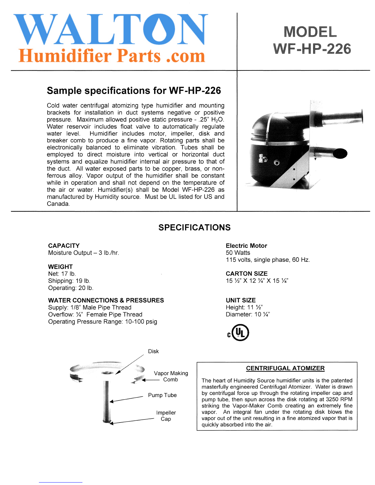
Your Humidity Source humidifier
is
a precision-built
instrument that, given proper care, will provide years
of
dependable service. All that is required is periodic cleaning
during the humidifying season when your humidifier is most
used. Depending on local water conditions, mineral solids and
other matter may accumulate
in
various parts
of
the unit.
These accumulations must be removed so that water flows
freely for efficient operation
of
the humidifier. A reverse
osmosis water treatment system will remove minerals and
greatly reduce the need to clean the humidifier.
Dome
Atomizing
Unit
Pump
Tube oo
..
~
Of Pump Tube
Showing Apertures
Reservoir
CLEAN YOUR HUMIDIFIER AT END OF THE HEATING
SEASON. LEAVE THE UNIT EMPTY AND DRY
DURING THE SUMMER MONTHS. REFILL AGAIN
IN
THE
FALL. INSPECT AND CLEAN (IF NEEDED) ONCE
OR
TWICE DURING THE HEATING SEASON.
IF
USED ALL
YEAR, INSPECT AND CLEAN AS NECESSARY
QUARTERLY
STEP 1.
DISCONNECT ELECTRICAL PLUG FROM HOUSE LINE.
TURN OFF WATER SUPPLY.
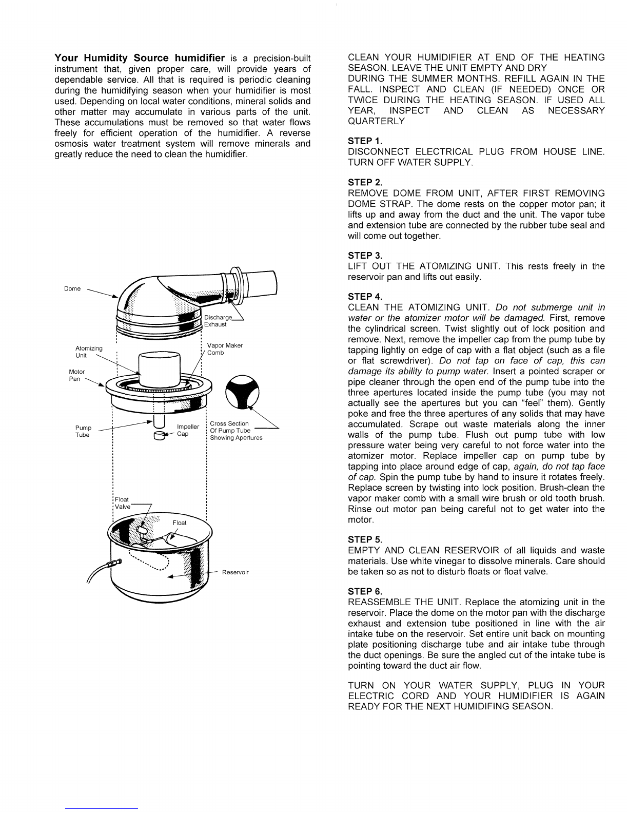
STEP 2.
REMOVE DOME FROM UNIT, AFTER FIRST REMOVING
DOME STRAP. The dome rests on the copper motor pan; it
lifts up and away from the duct and the unit. The vapor tube
and extension tube are connected by the rubber tube seal and
will come out together.
STEP
3.
LIFT OUT THE ATOMIZING UNIT. This rests freely
in
the
reservoir pan and lifts out easily.
STEP 4.
CLEAN THE ATOMIZING UNIT. Do not submerge unit
in
water
or
the atomizer motor will be damaged. First, remove
the cylindrical screen. Twist slightly out
of
lock position and
remove. Next, remove the impeller cap from the pump tube by
tapping lightly on edge
of
cap with a flat object (such as a file
or flat screwdriver). Do not tap
on
face
of
cap,
this can
damage its ability to pump water. Insert a pointed scraper or
pipe cleaner through the open end
of
the pump tube into the
three apertures located inside the pump tube (you may not
actually see the apertures but you can "feel" them). Gently
poke and free the three apertures
of
any solids that may have
accumulated. Scrape out waste materials along the inner
walls
of
the pump tube. Flush out pump tube with low
pressure water being very careful to not force water into the
atomizer motor. Replace impeller cap on pump tube by
tapping into place around edge
of
cap, again, do not tap face
of
cap.
Spin the pump tube by hand to insure it rotates freely.
Replace screen by twisting into lock position. Brush-clean the
vapor maker comb with a small wire brush or old tooth brush.
Rinse out motor pan being careful not to get water into the
motor.
STEP
5.
EMPTY AND CLEAN RESERVOIR
of
all liquids and waste
materials. Use white vinegar to dissolve minerals. Care should
be taken so as not to disturb floats
or
float valve.
STEP
6.
REASSEMBLE THE UNIT. Replace the atomizing unit
in
the
reservoir. Place the dome on the motor pan with the discharge
exhaust and extension tube positioned in line with the air
intake tube on the reservoir. Set entire unit back on mounting
plate positioning discharge tube and air intake tube through
the duct openings.
Be
sure the angled cut
of
the intake tube is
pointing toward the duct air flow.
TURN
ON
YOUR WATER SUPPLY, PLUG
IN
YOUR
ELECTRIC CORD AND YOUR HUMIDIFIER
IS
AGAIN
READY FOR THE NEXT HUMIDIFING SEASON.

MODEL WF-HP-226 Replacement Parts
Description
c-t//I'------I//~
Dome Strap Assembly
Part Number
079590
P-825 Humidistat
Human Hair Element
Standard
Tube Seal 908576
Extension Tube Sealer 905528
Dome 905026
Channel Rubber 905582
Atomizing Assembly WFHP526
Motor Pan Gasket 905615
Impeller Cap 905503
Float Valve Assembly 079057
Reservoir 905062
Humidifier Accessories
W351
Humidistat
Electronic Sensor
r---",~-...,~
-
~
~
I.
For high humidity
And/or close
tolerances
Humidity Source Reverse Osmosis water
Treatment systems. Sizes range from industrial
capacities down to individual room units.
'--
Table of contents
Other Walton Humidifier manuals