W&H Lisq VA131-17 User manual

Posizione logo
Instructions for use
VA131-17
VA131-22
VA131 ENG - Rev. 4

S mbols displa ed on the product and/or used in this manual:
WARNING!
Risk of injur
ATTENTION!
To prevent damage occurring
General explanations, without risk to
persons or objects
HOT SURFACES!
Risk of burns
Thermo washer
disinfectable
S mbols
2
HOT STEAM!
Risk of burns
Call service
Consult instruction for use Do not dispose of with
normal waste

Contents
3
1. Introduction . . . . . . . . . . . . . . . . . . . . . . . . . . . . . . . . . . . . . . . . . . . . . . . . . . . . . . . . . . . . . . . . . . . . . . . . . . . . . . . . . . . . . . . . . . . . . . . . . . . . . . . . . . . . . . . . 4
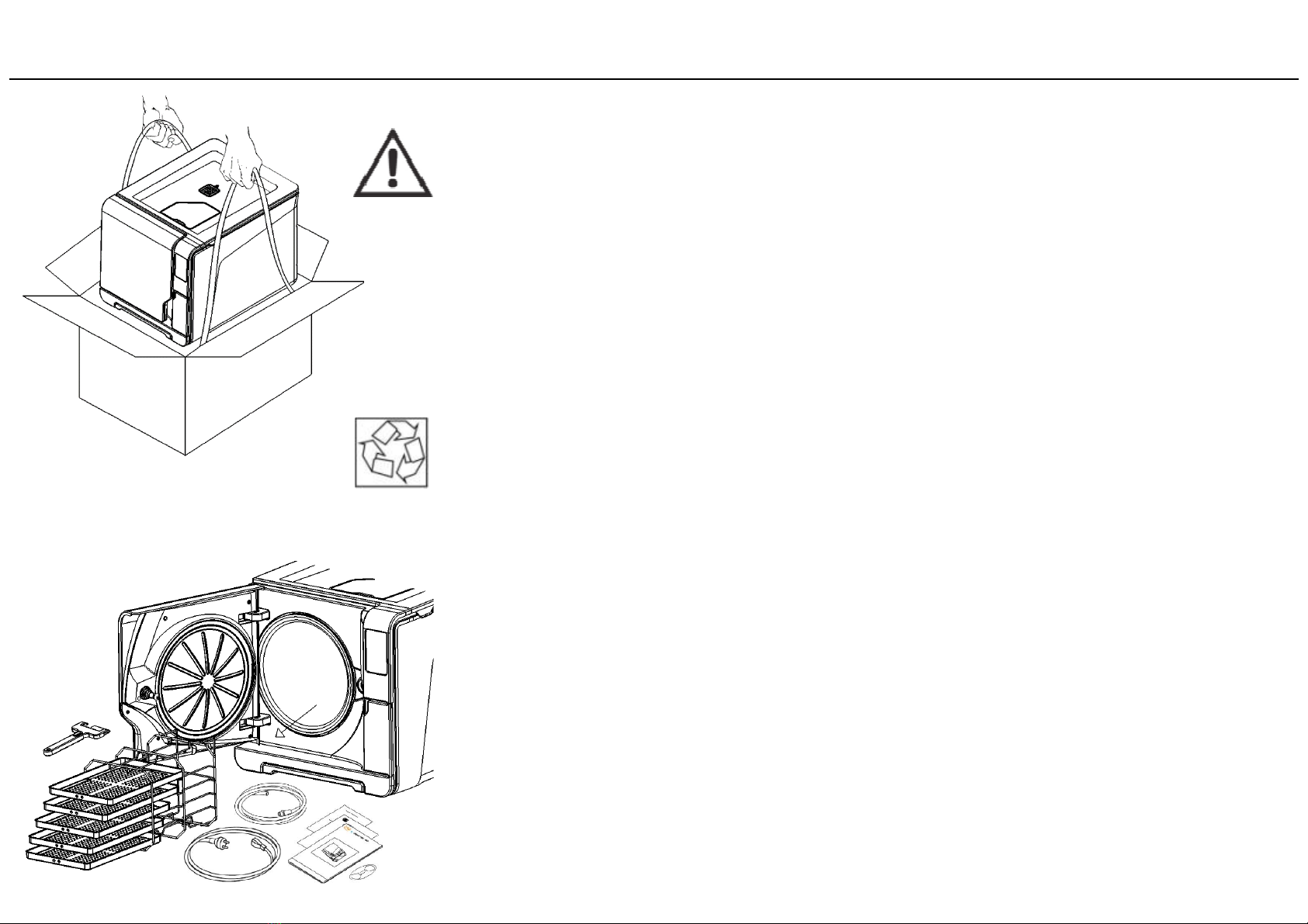
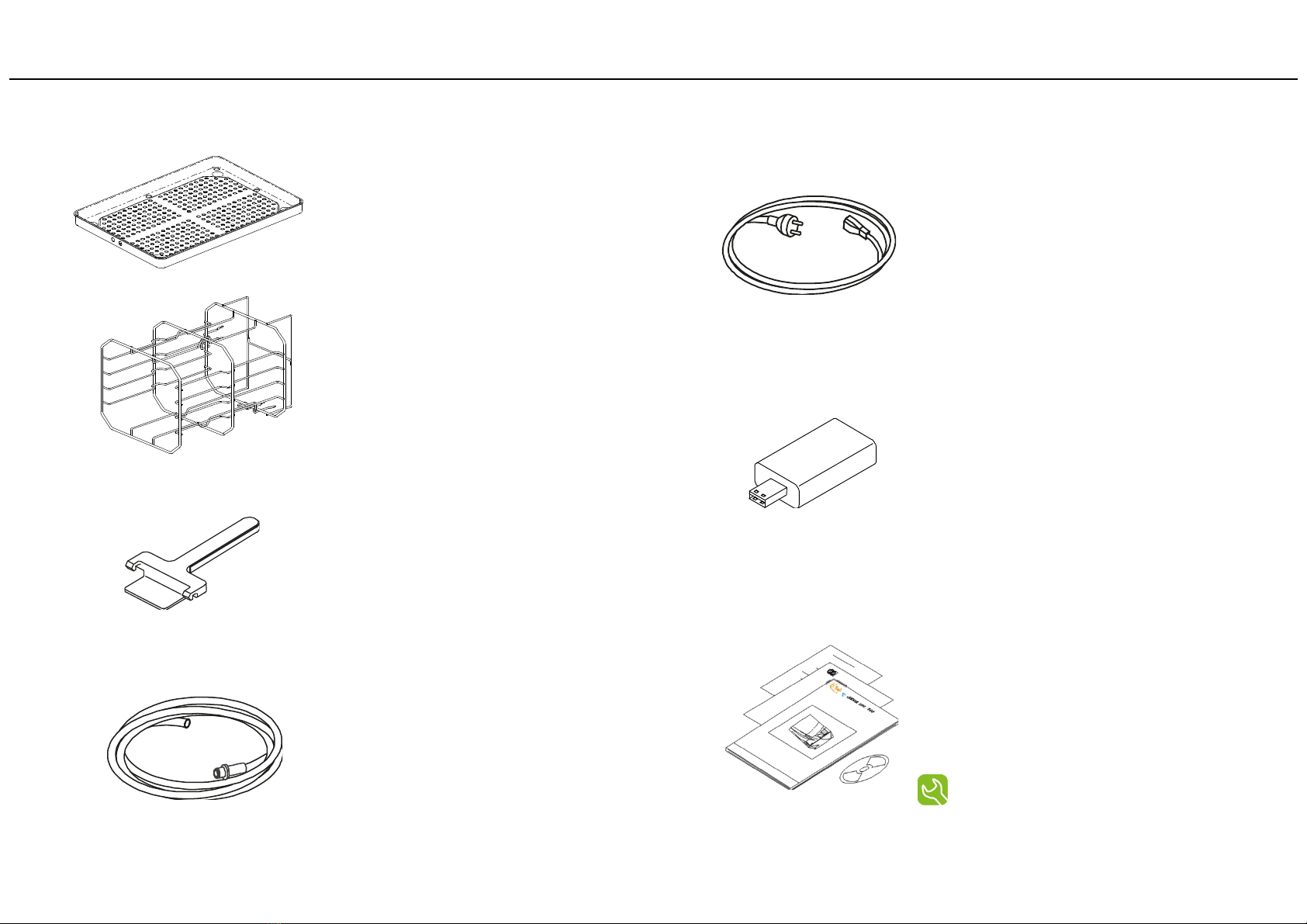
2. Unpacking . . . . . . . . . . . . . . . . . . . . . . . . . . . . . . . . . . . . . . . . . . . . . . . . . . . . . . . . . . . . . . . . . . . . . . . . . . . . . . . . . . . . . . . . . . . . . . . . . . . . . . . . . . . . . . . . . . 6
3. Safet advice . . . . . . . . . . . . . . . . . . . . . . . . . . . . . . . . . . . . . . . . . . . . . . . . . . . . . . . . . . . . . . . . . . . . . . . . . . . . . . . . . . . . . . . . . . . . . . . . . . . . . . . . . . . . . . . . 8
4. Installation, programming and setup . . . . . . . . . . . . . . . . . . . . . . . . . . . . . . . . . . . . . . . . . . . . . . . . . . . . . . . . . . . . . . . . . . . . . . . . . . . . . . . . . . . . . . . . . . . 9
5. The available sterilization c cles . . . . . . . . . . . . . . . . . . . . . . . . . . . . . . . . . . . . . . . . . . . . . . . . . . . . . . . . . . . . . . . . . . . . . . . . . . . . . . . . . . . . . . . . . . . . . . 41
6. Running a sterilization c cle . . . . . . . . . . . . . . . . . . . . . . . . . . . . . . . . . . . . . . . . . . . . . . . . . . . . . . . . . . . . . . . . . . . . . . . . . . . . . . . . . . . . . . . . . . . . . . . . . . 46
7 C cle histor . . . . . . . . . . . . . . . . . . . . . . . . . . . . . . . . . . . . . . . . . . . . . . . . . . . . . . . . . . . . . . . . . . . . . . . . . . . . . . . . . . . . . . . . . . . . . . . . . . . . . . . . . . . . . . . . 56
8 Maintenance . . . . . . . . . . . . . . . . . . . . . . . . . . . . . . . . . . . . . . . . . . . . . . . . . . . . . . . . . . . . . . . . . . . . . . . . . . . . . . . . . . . . . . . . . . . . . . . . . . . . . . . . . . . . . . . . 58
9 Troubleshooting, Errors, Messages and Alerts . . . . . . . . . . . . . . . . . . . . . . . . . . . . . . . . . . . . . . . . . . . . . . . . . . . . . . . . . . . . . . . . . . . . . . . . . . . . . . . . . . . 67
10 Rec cling and disposal . . . . . . . . . . . . . . . . . . . . . . . . . . . . . . . . . . . . . . . . . . . . . . . . . . . . . . . . . . . . . . . . . . . . . . . . . . . . . . . . . . . . . . . . . . . . . . . . . . . . . . 76
ANNEXES
1 Technical data . . . . . . . . . . . . . . . . . . . . . . . . . . . . . . . . . . . . . . . . . . . . . . . . . . . . . . . . . . . . . . . . . . . . . . . . . . . . . . . . . . . . . . . . . . . . . . . . . . . . . . . . . . . . . . . 77
2 Maintenance of dental handpieces . . . . . . . . . . . . . . . . . . . . . . . . . . . . . . . . . . . . . . . . . . . . . . . . . . . . . . . . . . . . . . . . . . . . . . . . . . . . . . . . . . . . . . . . . . . . 78
3 Sterilization load preparation . . . . . . . . . . . . . . . . . . . . . . . . . . . . . . . . . . . . . . . . . . . . . . . . . . . . . . . . . . . . . . . . . . . . . . . . . . . . . . . . . . . . . . . . . . . . . . . . . . 79
4 Bowie & Dick test . . . . . . . . . . . . . . . . . . . . . . . . . . . . . . . . . . . . . . . . . . . . . . . . . . . . . . . . . . . . . . . . . . . . . . . . . . . . . . . . . . . . . . . . . . . . . . . . . . . . . . . . . . . . 81
5 Helix test . . . . . . . . . . . . . . . . . . . . . . . . . . . . . . . . . . . . . . . . . . . . . . . . . . . . . . . . . . . . . . . . . . . . . . . . . . . . . . . . . . . . . . . . . . . . . . . . . . . . . . . . . . . . . . . . . . . 82
6 Vacuum test . . . . . . . . . . . . . . . . . . . . . . . . . . . . . . . . . . . . . . . . . . . . . . . . . . . . . . . . . . . . . . . . . . . . . . . . . . . . . . . . . . . . . . . . . . . . . . . . . . . . . . . . . . . . . . . . . 83
7 Water qualit . . . . . . . . . . . . . . . . . . . . . . . . . . . . . . . . . . . . . . . . . . . . . . . . . . . . . . . . . . . . . . . . . . . . . . . . . . . . . . . . . . . . . . . . . . . . . . . . . . . . . . . . . . . . . . . . 84
8 Example of a c cle data report . . . . . . . . . . . . . . . . . . . . . . . . . . . . . . . . . . . . . . . . . . . . . . . . . . . . . . . . . . . . . . . . . . . . . . . . . . . . . . . . . . . . . . . . . . . . . . . . 85
9 Example of a traceabilit label . . . . . . . . . . . . . . . . . . . . . . . . . . . . . . . . . . . . . . . . . . . . . . . . . . . . . . . . . . . . . . . . . . . . . . . . . . . . . . . . . . . . . . . . . . . . . . . . 86
10 Accessories and spare parts . . . . . . . . . . . . . . . . . . . . . . . . . . . . . . . . . . . . . . . . . . . . . . . . . . . . . . . . . . . . . . . . . . . . . . . . . . . . . . . . . . . . . . . . . . . . . . . . . . 87
11 Helix test documentation form . . . . . . . . . . . . . . . . . . . . . . . . . . . . . . . . . . . . . . . . . . . . . . . . . . . . . . . . . . . . . . . . . . . . . . . . . . . . . . . . . . . . . . . . . . . . . . . . 91

1. Introduction
For our safet and the safet of our patients
The purpose of this manual is to provide ou with information about LISA sterilizers to ensure:
•proper installation and set-up;
•optimal use;
•safe and reliable operation;
•compliance with regular maintenance and servicing requirements.
4
Intended use of the product
LISA sterilizers are full automated bench top steam sterilizers that generate steam using electrical heaters.
LISA sterilizers are used for medical purposes, e.g. in general medical practices, dental offices, facilities for personal h giene and beaut care and
veterinar practices. The are also used for materials and equipment that is likel to be exposed to blood or bod fluids, e.g. instruments used b
beaut therapists, tattooists, bod piercers and hairdressers.
The t pes of loads that can be sterilized with Lisa sterilizers are described in Table 1 of the reference technical norm EN 13060. These loads include
solid, porous, hollow loads t pe A and hollow loads t pe B, unwrapped, single wrapped and double wrapped.
LISA sterilizers cannot be used to sterilize liquids or pharmaceutical products.
About this manual
This manual contains the Instructions for Use of the W&H sterilizers VA131-17 and VA131-22, hereinafter referred to as LISA 17 and
LISA 22.
All drawings, images and texts contained in this manual are the propert of the manufacturer.
All rights reserved. Even partial duplication of drawings, images or text is prohibited.
The information contained in this document is subject to change without prior notice.
Responsibilit of the manufacturer
The manufacturer can onl accept responsibilit for the safet , reliabilit and performance of the product when the product itself is
installed, used and serviced in accordance with the instructions for use.
Servicing b unauthorized persons invalidates all claims under warrant and an other claims.
Please carefull read the safet information in Chapter 3!

Qualifications of the users
There are two t pes of users who ma operate the sterilizer:
The ADMINISTRATOR (ADM) is the head of the clinic/practice, who is legall responsible for the efficienc of the h giene protocol in
place as well as the sterilization process. He/she is also responsible for the USERS’ training and the correct operation and
maintenance of the equipment.
The USERS are the persons who use the sterilizer according to the ADMINISTRATOR instructions. The must be trained in operating
the sterilizer and in its safe use. Training must be regular and evidence of the understanding shall be recorded.
Conformit to European Standards and Directives
Medical Device Directive 93/42/CEE for devices class IIb, in accordance with the Rule 15 – ANNEX IX of the above Directive.
Directive 97/23/CEE (PED – Pressure Equipment Directive) for ever sterilization chamber designed and manufactured in
conformit to the ANNEX 1 and to the procedure described in the module D1 Annex III.
See the Declaration of Conformit and the Warrant Card in the enclosed documents.
Introduction
5

2. Unpacking
If the sterilizer comes from a cold location, wait until all external and internal surfaces
are free from moisture before switching it ON.
The sterilizer must be removed from the box and transported b two people.
Weight: LISA 17: 50,2 kg
LISA 22: 51,7 kg
Check the external conditions of the box and the sterilizer. In case of an damage,
immediatel contact our dealer or the shipping agent that has carried out the
transport.
Open the front door.
All the accessories are in the sterilization chamber.
Remove all items except the tra s and the tra rack.
6
The packaging of the product is environmentall friendl and can be disposed of b
industrial rec cling companies.
However, we recommend to keep the original packaging should ou ever have to ship
or transport the sterilizer.

Contents of the package
Tra (5 pieces total)
Reversible rack
Tra holder
Drain tube
Mains cable
7
USB pen drive
Fast guide
Declaration of conformit
Documentation CD
Warrant card
Works tests report
Maintenance sheet

3. Safet advice
8
•The user is responsible for the proper installation, the correct use and maintenance of the sterilizer in accordance with the
instructions listed in this manual.
•The safet devices of the sterilizer are impaired when the product itself is not installed, used and serviced in accordance
with the instructions provided b the manufacturer.
•The sterilizer has not been designed for the sterilization of foodstuff or waste.
•The sterilizer must not be used in presence of explosive or flammable gases, vapours, liquids or solids.
•The chamber is automaticall heated up to high temperature as soon as the sterilizer is switched on – risk of burns!
•Ensure that the socket the mains cable is connected to is properl grounded.
•The tra s and the sterilization load are hot at the end of each c cle. Use tra or cassette holders to empt the sterilization chamber.
•Do not exceed the maximum load weight limits as specified in this manual (see Chapter 8).
•Do not remove the name plate or an label from the sterilizer.
•To avoid electrical short circuits, do not pour water or an other liquids over the sterilizer.
•Use onl the power cord set provided b the manufacturer.
•Switch off the sterilizer and unplug the mains cable before inspecting, carr ing out maintenance or servicing the sterilizer.
•All electric devices connected to the sterilizer shall be of Insulation Class II (double insulated) or higher.
•If the sterilizer is connected to a water suppl s stem, this must be fitted with a backflow preventing device compl ing to IEC 61770.
•Repairs, maintenance or service must be carried out b service technicians authorized b the manufacturer and using genuine spare
parts onl .
•In case of transport:
–Completel drain both water tanks (see section “Water Tanks” in Chapter 4).
–Allow the sterilization chamber to cool down.
–Use original or appropriate packaging.

4. Installation, programming and setup
9
Required minimum clearances
Back side: 25mm (defined b the protrusion in the back)
Right and left sides: 10 mm
Upper side: As required for filling the water tank, 50 mm minimum
Placement
Place the sterilizer on a flat and level surface, far from sources of heat and from flammable materials.
Do not place the sterilizer so that it is difficult to open the service door and operate on the controls behind it.
Do not place the sterilizer so that it is difficult to disconnect the power suppl plug.
Place the sterilizer in a well ventilated room.
The sterilizer must not be operated in presence of explosive atmospheres.
Electrical connection
The electrical power suppl to the sterilizer must fulfil all applicable standards in the countr of use, and must compl
with the data label on the back of the sterilizer.
Connect the cord set to the socket provided in the back of the sterilizer.
Use onl the cord set provided b the manufacturer.
The power plug must be connected to a wall socket compl ing with the following specifications (refer to product label).
Specification Version labelled 10A Version labelled 12A
Voltage and frequenc Single phase, 200 - 240 V, 50/60 Hz
Max. current 10 A 12 A
Overvoltage categor II
Automatic circuit breaker (min.) 10 A 12 A
Residual-current device 30 mA or less, if required b local regulations
Ground connection Required
All protection and safet devices must be certified according to applicable standards.

Water tanks
Filling the clean water tank
•Switch the sterilizer ON;
•Remove the cap from the tank inlet;
•Fill the water tank with app. 4 litres of distilled or demineralized water;
•Once the clean water tank is almost full, an audible tone sounds; stop filling;
•Place the cap to close the tank into its original position.
10
Draining the used and clean water tank
•Open the service door at the front of the sterilizer.
•Put a container (4 litres min) below the sterilizer and insert into it the free end of the drain tube.
•Insert the drain tube into the left connector (gre ) for the used water, or into the right connector
(blue) for the clean water.
•Let the water flow from the tank completel .
•Press the push-button on top of the quick connector to dislodge the drain tube.
Use onl distilled or demineralized water as described in ANNEX 7.
Do not add an chemical / additive to the water.
Clean water drain (blue)
Used water drain (gre )

Chamber furniture
11
The chamber furniture consists of the tra s and the tra rack.
Tra rack
Insert the rack into the sterilizer chamber, align it at the center/bottom of the chamber and push it
gentl into position until it clicks.
Usable space in the chamber
LISA 17: 195 x 195 x 297mm (WxHxD); equal to the volume of 11.5 litres.
LISA 22: 195 x 195 x 390mm (WxHxD); equal to the volume of 15 litres.
Before touching the chamber furniture, ensure the sterilization chamber is cold: risk of
burns!
The chamber rack is reversible and can accommodate 5 tra s horizontall or 3 cassettes / containers
verticall .
If inserted in a 90°rotated position, the rack holds 3 tra s or 3 cassettes / containers horizontall .
CLICK
CLICK

Controls, commands, connections (front side)
Service door
12
Mains switch
Bacteriological filter
Used water drain (gre ) Clean water drain (blue)
Touch screen
Water tank cover
Tank filling cover - cap
Door pin
Sterilization chamber
Door seal
Chamber door
Dust filter
Service door
USB port
Identification label

13
Water suppl inlet
Used water drain
Condenser grid
Mains cable guide
Mains plug socket
Serial communication port (male)
Pressure safet valve cover
Connections (rear side)
The water suppl s stem must deliver demineralized water meeting the requirements as listed in ANNEX 7.
Do not add an chemical / additive to the water.
The manufacturer’s warrant is void if the sterilizer was used with water containing either chemical additives, or contaminant levels exceeding
those listed in ANNEX 7.
The water suppl s stem must be fitted with a backflow preventing device compl ing to IEC 61770 and to national and local regulations.
Maximum pressure: 8.6 bar, minimum flow 2.5 litres/min , max. temperature 35 °C.
Ethernet port
USB ports

14
Switching ON the sterilizer
Press the mains switch behind the service door to switch ON the sterilizer.
The visual indicator on the mains switch turns green and the CYCLE SELECTION screen (HOME screen)
(see next page) appears.
Energ management: the SLEEP mode
In the SLEEP mode the displa remains dark and the sterilizer chamber is no longer heated to save energ .
You ma enable the sterilizer to enter the SLEEP mode automaticall after being left unattended for a certain period of time.
Touch in sequence MENU – SETTINGS – ENERGY MANAGEMENT (see LIST OF MENU OPTIONS in the further pages).
To exit the SLEEP mode:
- Touch the SLEEP button on the screen, or
- Open or (if it is open) close the chamber door.
Controls and commands
To enter the SLEEP mode manuall :
- From the CYCLE SELECTION screen
(HOME screen), touch the SLEEP
button.

ICONS: show the available options/actions.
FOOTER: Shows additional icons that could be used for some common actions (like
MENU, BACK, NEXT, CONFIRM, HOME and so on)
HEADER: Shows the title/purpose of the screen or the c cle number and the current
date and time.
TYPICAL SELECTION SCREEN (example: CYCLE SELECTION SCREEN/HOME screen)
Touch screen and Commands
B touching an icon, ou:
- select an item in the menu, or
- undertake an action.
NOTE: An icon in gre colour means that the relevant function is disabled.
15

Touch screen and Commands
TYPICAL KEYBOARD SCREEN (to enter letters and numbers)
HEADER: Shows the title/purpose of the screen and the current date and time.
DATA ENTERING FIELD: shows the letters/numbers ou are t ping.
SPECIAL KEYS: see table
FOOTER
Shows the CONFIRM and BACK icons
TYPING FIELD: touch a ke to t pe into the data entering field.
16
KEY WHAT IT DOES
Activates capital letters.
Cancels the last letter / number t ped.
Activates number ke board.
Activates letter ke board.
Space.

The active selection (example: English) appears in a frame in green colour.
To activate another selection (example: French), simpl touch the item in the list, then press BACK.
TYPICAL SCREEN TO SELECT FROM A LIST (example: language selection)
Touch screen and Commands
If the list is longer than displa ed, ou ma scroll it b touching the icons SCROLL UP – SCROLL DOWN in
the footer.
Some auxiliar functions are also available in the footer (like BACK, HOME, etc.)
TYPICAL SCREEN TO SET PARAMETERS (example: date and time setting)
If ou want to change a numeric setting (e.g. the current hour), simpl touch it. Its colour turns green and
a green frame appears, the UP and DOWN icons appear to permit changing the value.
If the parameter is a setting (e.g. the date format), simpl touch the one ou want: its colour turns green.
B pressing BACK, the parameter is set.
17

18
Control icons
The following icons appear in the bottom or in other specific areas of the screen. The permit to activate specific functions that are
appropriate for the situation (e.g. choosing options, entering values, replacing consumables, etc.).
ICON WHAT IT DOES / MEANS
SLEEP MODE
Enters or exits the SLEEP mode.
BACK
Moves to the previous screen or scrolls to the previous page, if an .
NEXT
Moves to the next screen or scrolls to the next page, if an .
HOME
Moves to the CYCLE SELECTION screen (HOME screen).
MENU
Accesses to the sub-menus.
SETTINGS
Provides access to the SETTING screen of a specific area (e.g. c cle settings, connettivit settings, etc).
INFO
Shows the INFO screen (list of all operating parameters of the sterilizer).
OTHER SETTINGS
Opens a screen with other settings/options
Active selection frame
CONFIRM / YES
Confirms the active option. Saves a setting or a parameter. Answers YES to a question.
CANCEL / NO
Aborts the action/function. Moves to the previous screen without confirming/making an changes nor saving an parameters.
Answers NO to a question.

ICON WHAT IT DOES / MEANS
ECO-DRY
If shown during a c cle, reminds ou that the ECO – DRY option with extended dr ing is operating automaticall .
ECO-DRY plus
If shown during a c cle, reminds ou that the ECO – DRY PLUS option is operating automaticall .
UP / DOWN
Increases (UP) and decreases (DOWN) a number or a parameter.
VIDEO
Watch a video animation.
PLAY / PAUSE
Pla s/Pauses a video.
DOOR LOCKED
The door is locked. Don't tr to open the door. During a sterilization c cle this does not indicate an anomal .
DOOR UNLOCKED - UNLOCKING
The door is unlocked: You ma open the door. Also appears during unlocking ( ou ma hear the motor working): wait.
DAILY PROGRAMMABLE CYCLE START
Enters the function to program a succession of c cles for dail repetition.
ON / OFF SWITCH
These switch-looking icons are used to set an option ON or OFF. Touch to change the status.
OPTION STATUS
Empt dot: the option is inactive. Filled dot: the option is active. Touch to change the status.
OPTION ENABLED
Checkmark: option enabled. Empt square: option disabled. Touch to change the status.
ADMINISTRATOR
Indicates that the referenced user has the same authorit as the ADMINISTRATOR
HELP
Opens a page of explanations about the current function
19
Control icons

MENU SUB-MENU WHAT IT DOES
Continues
on the next
page
Sets the language from a "selection from list" screen.
Sets time and date values and format.
TIME AND DATE: Touch the figure ou want to change and use the UP / DOWN ke s to set.
FORMAT: Touch the format ou want to set.
Sets a name for the sterilizer, to be printed on c cle reports (the name ma the same as the dental clinic).
Use the ke board to t pe the name and the CONFIRM icon to save it.
Sets the SLEEP mode ON or OFF with a switch-shaped icon.
For energ saving purpose, it is suggested to set it ON.
Sets the time before the sterilizer will enter the SLEEP mode. Use the UP
and DOWN ke s to set.
Sets the displa brightness. Touch the UP or DOWN button to increase or decrease the value.
Permits to choose between melodies and beep tones.
If disabled, onl the sounds requested b mandator standards are enabled (error,
start c cle, end c cle, etc.…). If enalbled, all sounds are enabled.
(*) Select the c cles that shall be available for the user in the CYCLE SELECTION screen (HOME screen).
Sets the units for pressure, temperature and water qualit .
Permits to program a sequence of c cles to be run on dail basis.
20
List of the MENU options
Note (*) This option is available for the ADMINISTRATOR onl . See USER AUTENTICATION for instructions about how to log in as an ADMINISTRATOR.
This manual suits for next models
1
Table of contents
Other W&H Steriliser manuals
Popular Steriliser manuals by other brands

AQUA EL
AQUA EL STERILIZER UV PS 2.0 operating instructions

J.P. SELECTA
J.P. SELECTA PRESOCLAVE II 80L instruction manual

Philips
Philips SCF276/33 Specification sheet

Twin-Star International
Twin-Star International M3 product manual

Philips AVENT
Philips AVENT AVENT SCF271/02 Specifications

Norka
Norka BUENOS AIRES UV-C 997 100 02 Series operating instructions