13
W&T
Subject to error and alteration
USB Isolators
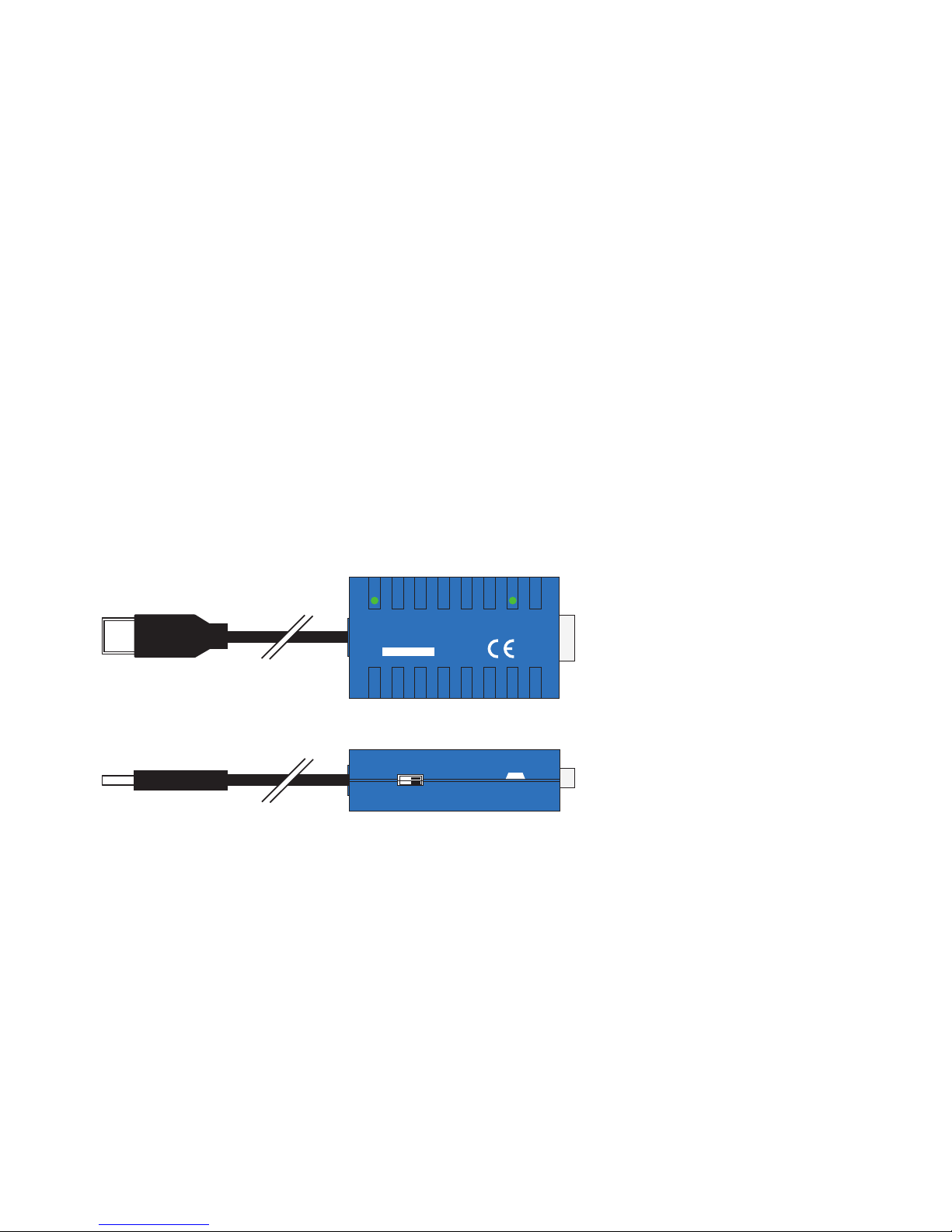
USB Isolator, 1kV, #33001
Function
The Wiesemann & Theis USB-Isolator #33001 provides galvanic
isolation for low-speed and full-speed USB connections with an
isolation voltage of at least 1000V DC. The Isolator eliminates
ground loops and prevents current from flowing between the
connected devices and the supply lines of the USB caused by
potential differences. The Isolator is simply inserted into the
existing USB connection and powered by an external power
supply.
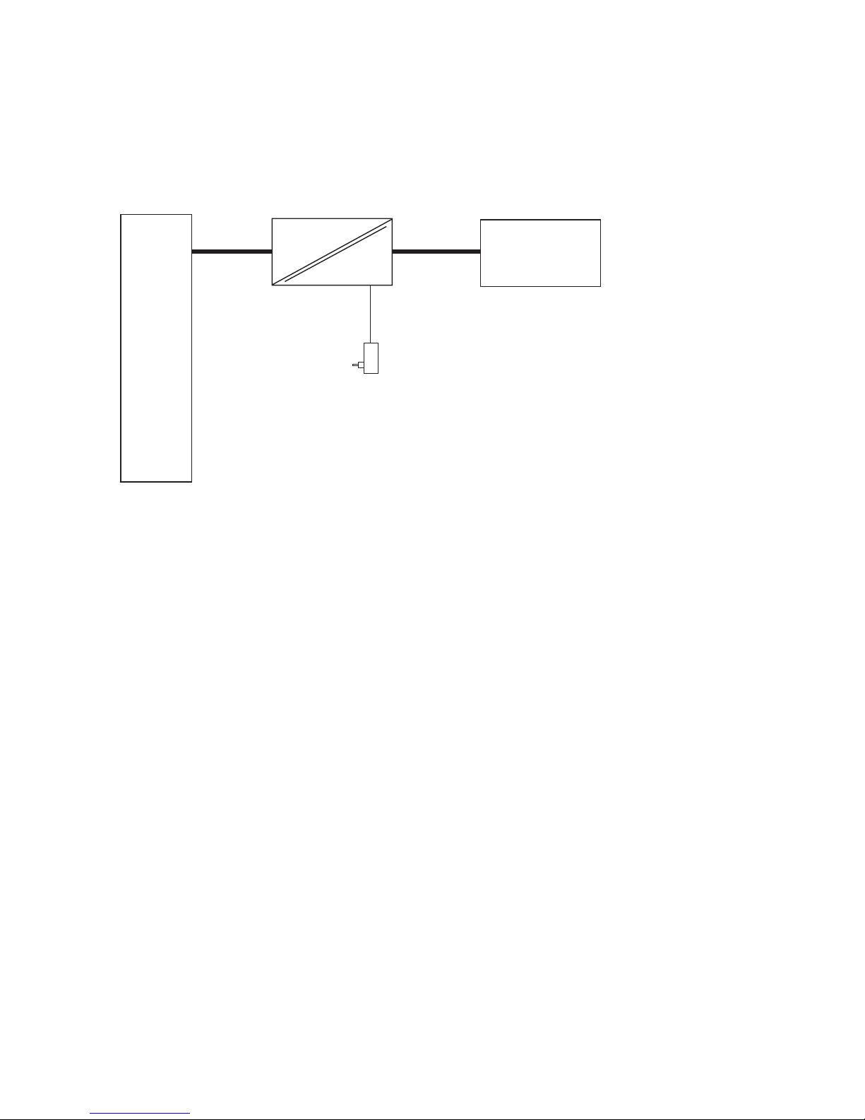
Supply voltage
The USB Isolator requires an external power supply for
powering the galvanically isolated Isolator side and a bus-
powered terminal device.
A suitable wall mount adaptor is included with the Isolator.
In principle any 5V DC power supply with a USB output can be
used as long as it provides an output current of at least 0.5A.
The supply voltage is brought to the Isolator side through a
mini-USB socket. The socket is marked on the Isolator as
„Power Connector.“ An appropriate adapter cable for connec-
ting the power supply is also included with the Isolator.
The USB A plug on the power cable must never be
connected to a second USB port on the USB host or hub
which is connected to the upstream port of the Isolator.
Such a connection would jumper the galvanic isolation
and make it ineffective. A galvanically isolated voltage
source is therefore absolutely mandatory.
1