Wandy 2R User manual

Wandy 2R client Manual
The Wandy unit is an “Active WiFi outdoor antenna”. The unit consist of an antenna with high gain and a WiFi-
Ethernet-client. The slim line enclosure is compact and made of all weather ABS for years of uninterruptible
operation. Long distance connections are easy with the Wandy 2R. Simple installation with Power Over Ethernet.
Build in router function provides extra security for internet connections. Wandy 2R for fast, stable and long range
WiFi connections.
Version 0.91

Table of Contents
1 Preface ..................................................................................................................................................................4
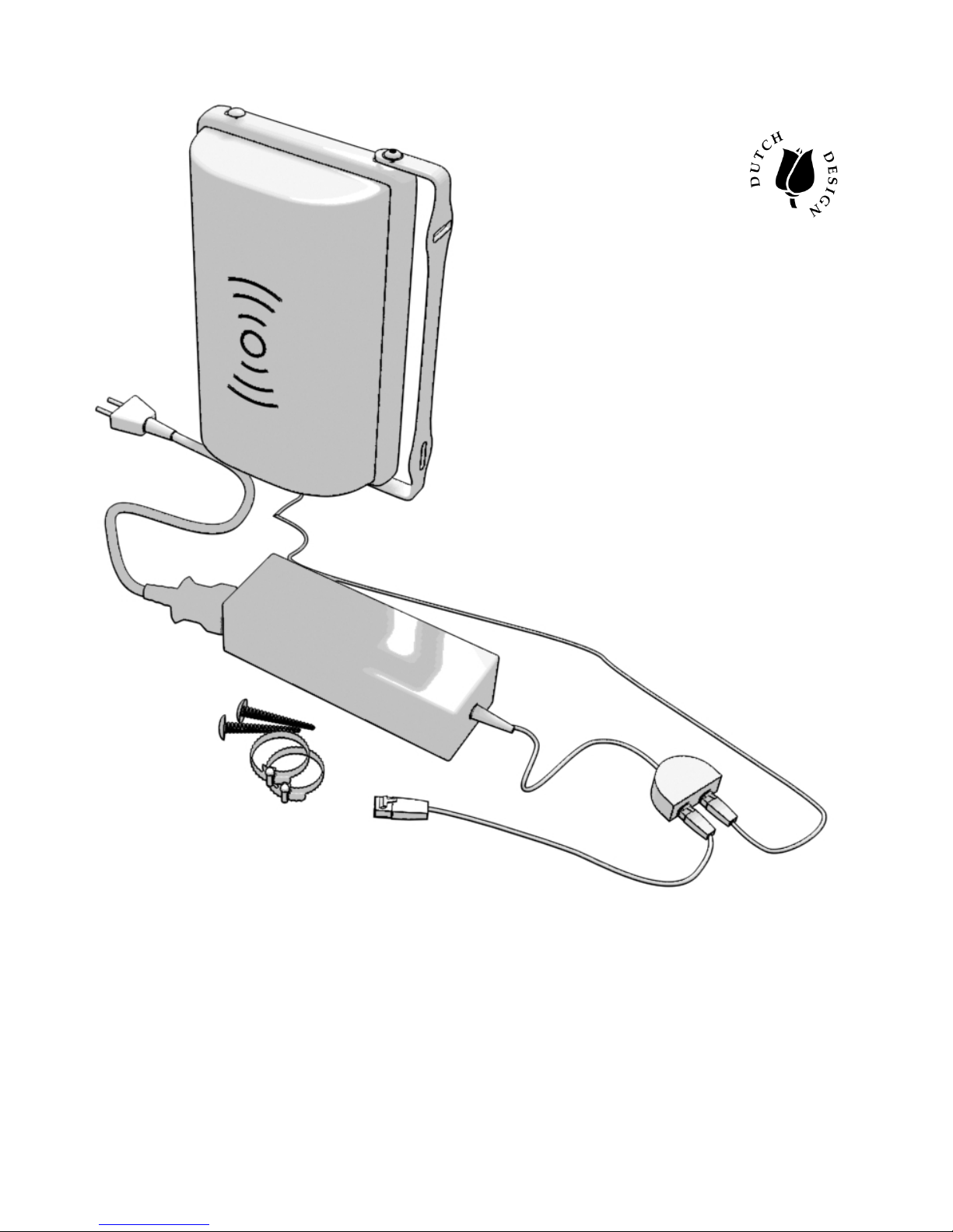
2 Packing List ...........................................................................................................................................................5
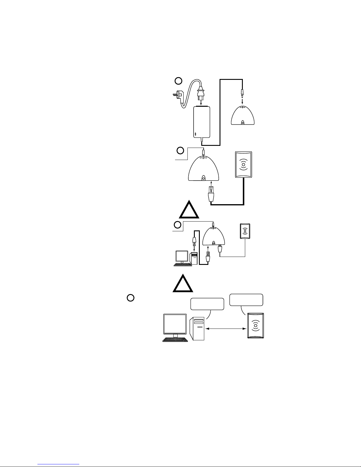
3 Configuration Wandy 2R .......................................................................................................................................6
4 Concept of the Wandy radio hardware................................................................................................................12
4.1 Wireless Interface..........................................................................................................................................12
4.2 Wireless to Wired connection........................................................................................................................12
5 Wireless...............................................................................................................................................................14
5.1 Basic settings.................................................................................................................................................14
5.2 Advanced settings .........................................................................................................................................15
5.3 Security..........................................................................................................................................................17
5.3.1 WEP Encryption Setting........................................................................................................................18
5.3.2 64-bit WEP Encryption..........................................................................................................................18
5.3.3 128-bit WEP Encryption........................................................................................................................19
5.3.4 WEP Encryption with 802.1x Setting....................................................................................................19
5.3.5 WPA Encryption Setting........................................................................................................................19
5.3.6 WPA Authentication Mode....................................................................................................................19
5.4 Access Control...............................................................................................................................................19
5.5 Configuring WDS...........................................................................................................................................20
5.6 WDS network topology ..................................................................................................................................21
5.6.1 Bus topology .........................................................................................................................................21
5.6.2 Star topology.........................................................................................................................................22
5.6.3 Ring Topology.......................................................................................................................................22
5.6.4 Mesh topology.......................................................................................................................................23
5.7 WDS Application............................................................................................................................................23
5.7.1 Wireless Repeater.................................................................................................................................23
5.7.2 Wireless Bridge.....................................................................................................................................24
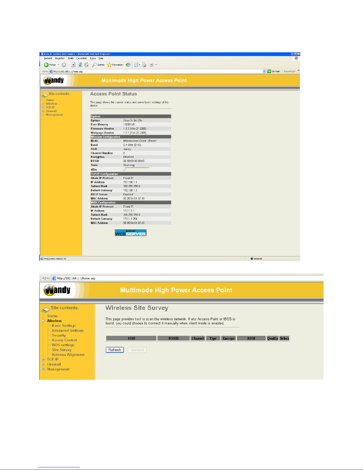
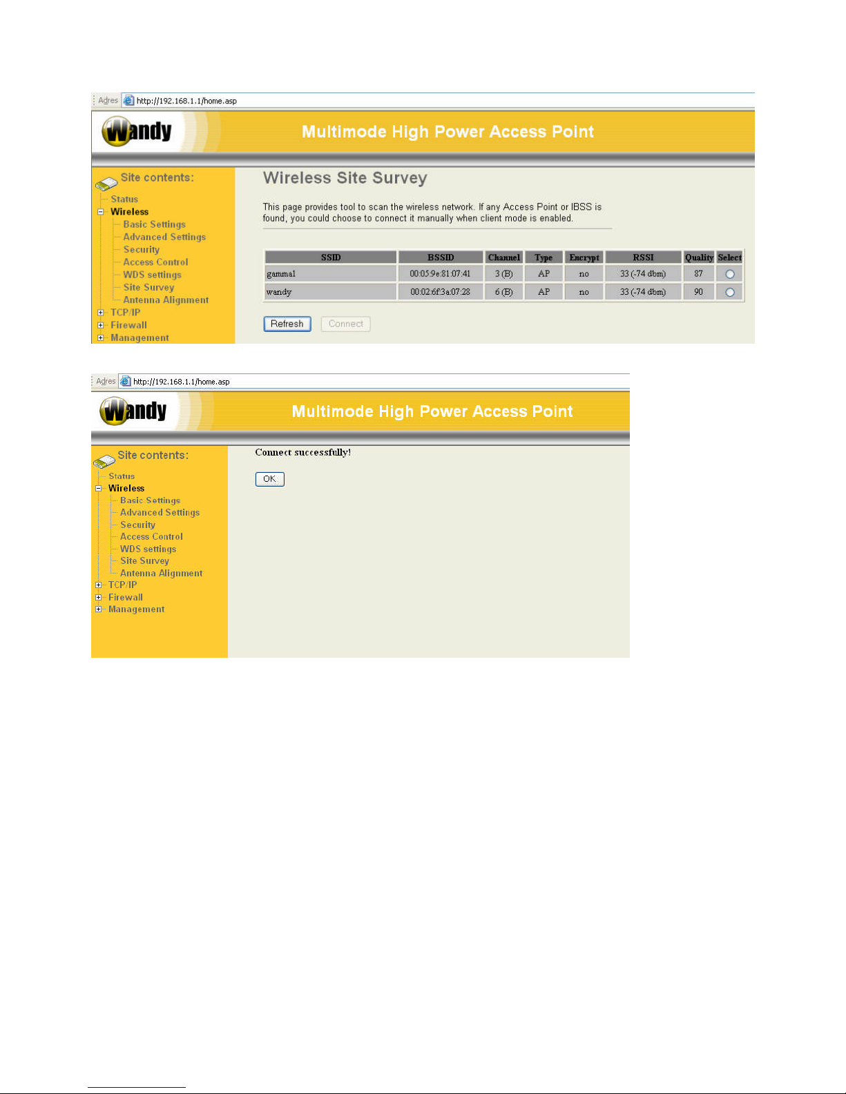
5.8 Site Survey.....................................................................................................................................................24
5.9 Antenna Aligment ..........................................................................................................................................24
6 TCP/IP.................................................................................................................................................................26
6.1 Configuring LAN Interface.............................................................................................................................26
6.1.1 DHCP disabled......................................................................................................................................26
6.1.2 DHCP Client..........................................................................................................................................26
6.1.3 DHCP Server ........................................................................................................................................26
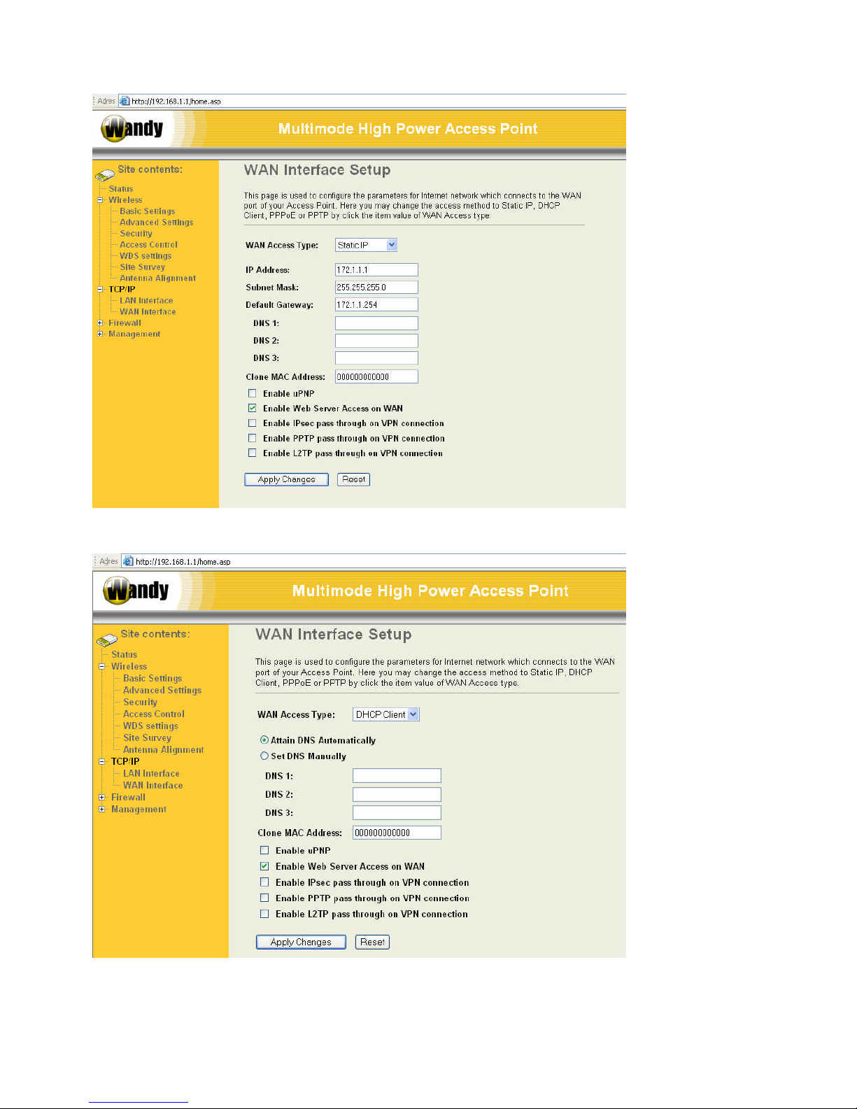
6.2 Configuring WAN Interface............................................................................................................................27
6.2.1 Static IP.................................................................................................................................................27
6.2.2 DHCP Client (Dynamic IP)....................................................................................................................28
6.2.3 PPPoE...................................................................................................................................................29
6.2.4 PPTP.....................................................................................................................................................30
7 Firewall ................................................................................................................................................................32
7.1 Port Filtering...................................................................................................................................................32
7.2 IP Filtering......................................................................................................................................................32
7.3 MAC Filtering.................................................................................................................................................33
7.4 Port Forwarding (Virtual Server)....................................................................................................................33
7.5 DMZ ...............................................................................................................................................................34
8 Management........................................................................................................................................................35
8.1 Wizard............................................................................................................................................................35
8.2 Operation Mode.............................................................................................................................................35
8.2.1 Router ...................................................................................................................................................36
8.2.2 Bridge....................................................................................................................................................36
8.2.3 WISP (Wireless ISP).............................................................................................................................36
8.3 Bandwidth Control .........................................................................................................................................37
8.4 Statistics.........................................................................................................................................................37
8.5 Dynamic DNS Setting....................................................................................................................................37
8.6 Time Zone......................................................................................................................................................38
8.7 Log.................................................................................................................................................................38
8.8 Upgrade Firmware.........................................................................................................................................39
8.9 Save/Reload Settings ....................................................................................................................................39
8.10 Password...................................................................................................................................................40
8.11 Reboot.......................................................................................................................................................40

9 SSH login.............................................................................................................................................................42

1 Preface
Thank you very much for buying the Wandy 2R unit. With this unit you do have a powerful combination of
electronics and antenna technology. Long distance outdoor WiFi connections are easily made by the simple
installation. Optimal performance is possible by free line of signed between the Wandy2R and the access point.
The setup procedure is
Connect the power to the Wandy2R unit Connect the PC to the Wandy 2R unit
Configure the Wandy2R for wireless network Install Wandy2R outdoor
Enjoy years of uninterruptible use of the Wandy2R
Connect the power to the Wandy 2R unit
Connect the PC to the Wandy 2R unit
Configure Wandy 2R for wireless network
Install Wandy 2R outdoor
Enjoy the years of uninterruptible use of the Wandy 2R

2 Packing List
Before you start to install the Wandy 2R, make sure the package contains the following items
This package contains Manual Quick start
Wandy2R unit Power adapter Wall mount
plugs
Mounting bracket Power cable Wall mount
screws
1M cross cable Pole mount
hardware
Mounting
bracket bolts
POE inserter unit Inbus tool
If anything is missing contact your supplier of the Wandy 2R

3 Configuration Wandy 2R
Before installing the Wandy 2R unit outside it is best to configure first the unit indoor.
Connect the power supply to
the POE inserter unit. P+DATA
OUT
DATA
IN
POWER IN
+ -
A
Connect the Wandy 2R unit to
the POE inserter unit. Wait one
minute to let the unit boot.
P+DATA
OUT
DATA
IN
POWER IN
+ -
!
For the wandy unit use the
P+DATA OUT port!
B
Connect the PC to the POE
inserter unit.
P+DATA
OUT
DATA
IN
POWERIN
+-
!
Connect your computer to the
DATA IN port!
Don't plug your computer in the
P+DATA OUT you can seriously
damage your hardware!
D
Configure the wandy unit by
the web interface
Hi Wandy,
How are you?
Fine, thanks!
192.168.1.2
192.168.1.1
Username: root
Password: wandy
Enter Wandy's
configuration
page.
F
3.1 Wandy 2R in WISP mode
In this setup we will configure the default Wandy 2R unit to connect to an AP with SSID gamma1 and use the build
in router function.
The default config of the Wandy 2R unit is WISP mode. The wireless interface is in WiFi client mode and
connected to the Ethernet interface trough a router.
The default IP number if the Ethernet interface is 192.168.1.1

Open the web interface of the Wandy 2R unit at IP 192.168.1.1
Select in the menu Wireless the option site survey
Press refresh to let the Wandy 2R unit make site survey

We connect to the wireless network with SSID gamma1 by selecting this network and pressing connect.
We now configure the Wandy 2R unit to get an IP address from the AP.
Open the menu TCP/IP and then WAN interface

Change WAN access Type to DHCP client to get an IP address form the AP to the Wandy 2R. Set the Attain DNS
Automatically. This will set automatically the DNS servers from the AP.
Press Apply Changes to make the setting effective
Click on status to see the current status of the unit

In the status screen we can see that the unit is connected to AP with SSID gamma1
The Wireless interface (WAN) does have IP number 192.168.16.105 with gateway 192.168.16.2
The LAN interface does have IP number 192.168.1.1 with a DHCP server enabled.
Signal strength is -76 dBm.
The Wandy 2R is connected to an access point and has a router between the wireless interface and the wired.
On the PC set the gateway to the wandy 2R unit 192.168.1.1 to complete the setup.

3.2 Wandy 2R in Bridge mode
In this setup we will configure the default Wandy 2R unit to connect to an AP with SSID gamma1 and make a
transparent connection between the wireless interface and wired.
Open the web interface of the Wandy 2R unit at IP 192.168.1.1
First change the operation mode of the Wandy 2R into bridge mode
Select in management Operation Mode

4 Concept of the Wandy 2R radio hardware
The Wandy 2R has two interfaces
Wireless interface
Wired interface
These two interfaces are connected together with or without a router between them.
In bridge mode the wireless and Ethernet are directly connected. No routing or translating is done. In this mode the
unit can be used as a transparent device. The Wandy 2R can be even in different IP range.
4.1 Wireless Interface
The wireless radio of the device can acts as the following roles.
AP (Access Point)
The wireless radio of device serves as communications “hub” for wireless clients and provides a connection to a
wired LAN.
AP Client
This mode provides the capability to connect with the other AP using infrastructure/Ad-hoc networking types. With
bridge operation mode, you can directly connect the wired Ethernet port to your PC and the device becomes a
wireless adapter. And with WISP operation mode, you can connect the wired Ethernet port to a hub/switch and all
the PCs connecting with hub/switch can share the same public IP address from your ISP.
WDS (Wireless Distribution System)
This mode serves as a wireless repeater, the device forwards the packets to another AP with WDS function. When
this mode is selected, all the wireless clients can’ survey and connect to the device. The device only allows the
WDS connection.
WDS+AP
This mode combines WDS plus AP modes, it not only allows WDS connections but also the wireless clients can
survey and connect to the device.
4.2 Wireless to Wired connection
The Wireless and Wired interface can be connected together with or without a router function.
Router
The wired Ethernet (WAN) port is used to connect with ADSL/Cable modem and the wireless NIC is used for your
private WLAN. The NAT is existed between the 2 NIC and all the wireless clients share the same public IP address
through the WAN port to ISP. The default IP configuration for WAN port is static IP. You can access the web server
of device through the default WAN IP address 172.1.1.1 and modify the setting base on your ISP requirement.
Bridge
The wired Ethernet and wireless NIC are bridged together. Once the mode is selected, all the WAN related
functions will be disabled.
WISP (Wireless ISP)
This mode can let you access the AP of your wireless ISP and share the same public IP address form your ISP to
the PCs connecting with the wired Ethernet port of the device. To use this mode, first you must set the wireless
radio to be client mode and connect to the AP of your ISP then you can configure the WAN IP configuration to meet
your ISP requirement.
The following table shows the supporting combination of operation and wireless radio modes.
Bridge Router WISP
AP Yes Yes No

WDS Yes Yes No
Client Yes No Yes
AP+WDS Yes Yes No

5 Wireless
In this menu it will be possible to configure the device for all the wireless settings. To change to operation mode go
the menu Management.
5.1 Basic settings
Disable Wireless LAN Interface
Disable the wireless interface of device
Band The device supports 2.4GHz(B), 2.4GHz(G) and 2.4GHz(B+G) mixed modes. Mode:
The radio of device supports different modes as following:
Mode:
AP The radio of device acts as an Access Point to serves all wireless clients to join a wireless local network.
Client Support Infrastructure and Ad-hoc network types to act as a wireless adapter.
WDS Wireless Distribution System, this mode serves as a wireless repeater, only devices with WDS function
supported can connect to it, all the wireless clients can’t survey and connect the device when the mode is
selected.
AP+WDS
Support both AP and WDS functions, the wireless clients and devices with WDS function supported can
survey and connect to it.
Network type:

Infrastructure:
This type requires the presence of 802.11b/g Access Point. All communication is done via the Access
Point.
Ad Hoc:
This type provides a peer-to-peer communication between wireless stations. All the communication is done
from Client to Client without any Access Point involved. Ad Hoc networking must use the same SSID and
channel for establishing the wireless connection.
Channel Number
The channel the unit will operate on. When set to “Auto”, the device will find the least-congested channel for use.
Enable Mac Clone (Single Ethernet Client)
The MAC address of the unit will be the MAC address of the PC connected to the Wandy 2R unit. This canb only
be done in Client mode.
Enable Universal Repeater Mode
Universal repeater mode will make the Wandy 2R unit become client as well as AP on the same radio. In this mode
it can repeater any vendor AP.
Extended SSID:
The SSID of the Universal repeater mode can be different from the AP the client is connected to.
5.2 Advanced settings
These settings are only for more technically advanced users who have sufficient knowledge about wireless LAN.
These settings should not be changed unless you know what effect the changes will have on your device. The
default setting is optimized for the normal operation. For specific application, setting configuration will required
highly attention to reach optimistic condition.
Any unreasonable value change to default setting will reduce the throughput of the device.

Authentication Type
The device supports two Authentication Types “Open system” and “Shared Key”. When you select “Share Key”,
you need to setup “WEP” key in “Security” page (See the next section). The default setting is “Auto”. The wireless
client can associate with the device by using one of the two types.
Fragment Threshold
The fragmentation threshold determines the size at which packets are fragmented (sent as several pieces instead
of as one block). Use a low setting in areas where communication is poor or where there is a great deal of radio
interference. This function will help you to improve the network performance.
RTS Threshold
The RTS threshold determines the packet size at which the radio issues request to send (RTS) before sending the
packet. A low RTS Threshold setting can be useful in areas where many client devices are associating with the
device, or in areas where the clients are far apart and can detect only the device and not each other. You can enter
a setting ranging from 0 to 2347 bytes.
ACK timing.
For long distance 802.11G it will be necessary to increase the ACK timing value. When operating at
802.11B the ACK timing value needs to be at least 100. For short distance 802.11G the value can be less.
Data Rate
The standard IEEE 802.11b/11g supports 1, 2, 5.5,11/6, 9, 12, 18, 24, 36, 48 and 56 Mbps data rates. You can

choose the rate that the device uses for data transmission. The default value is “auto”. The device will use the
highest possible selected transmission rate.
Beacon Interval
The beacon interval is the amount of time between access point beacons in microseconds. The default beacon
interval is 100.
Broadcast SSID
Broadcasting the SSID will let your wireless clients find the device automatically. If you are building a public
Wireless Network, disable this function can provide better security. Every wireless stations located within the
coverage of the device must connect this device by manually configure the SSID in your client settings.
Int. Roaming
This function will let Wireless Stations roam among a network environment with multiple devices. Wireless Stations
are able to switch from one device to another as they move between the coverage areas. Users can have more
wireless working range. An example as the following figure
You should comply with the following instructions to roam among the wireless coverage areas.
For implementing the roaming function, the setting MUST comply the following two items.
1) All the devices must be in the same subnet network and the SSID must be the same.
2) If you use the 802.1 x authentication, you need to have the user profile in these devices for the roaming
station.
Block WLAN Relay (Isolate Client)
The device supports isolation function. If you are building a public Wireless Network, enable this function can
provide better security. The device will block packets between wireless clients (relay). All the wireless clients
connected to the device can’t see each other.
Transmit Power
The device supports four transmission output power levels 250, 200, 150 and 100mW for CCK (802.11b) mode and
two transmission output power levels 100 and 50mW for OFDM (802.11g) mode. User can adjust the power level
to change the coverage of the device. Every wireless stations located within the coverage of the device also needs
to have the high power radio. Otherwise the wireless stations only can survey the device, but can’t establish
connection with device.
5.3 Security
This device provides complete wireless security function include WEP, 802.1x, WPA-TKIP, WPA2-AES and WPA2-
Mixed in different mode (see the Security Support Table).
The default security setting of the encryption function is disabled. Choose your preferred security setting depending
on what security function you need.

5.3.1 WEP Encryption Setting
Wired Equivalent Privacy (WEP) is implemented in this device to prevent
unauthorized access to your wireless network. The WEP setting must be as same as each client in your wireless
network. For more secure data transmission, you can change encryption type to “WEP” and click the “Set WEP
Key” button to open the “Wireless WEP Key setup” page.
When you decide to use the WEP encryption to secure your WLAN, please refer to the following setting of the WEP
encryption:
5.3.2 64-bit WEP Encryption
64-bit WEP keys are as same as the encryption method of 40-bit WEP. You can input 10 hexadecimal digits (0-9,

a-f or A-F) or 5 ACSII chars.
The Default Tx Key field decides which of the four keys you want to use in your WLAN environment.
5.3.3 128-bit WEP Encryption
128-bit WEP Encryption 128-bit WEP keys are as same as the encryption method of 104-bit WEP. You can input
26 hexadecimal digits (0-9, a-f or A-F) or 10 ACSII chars.
The Default Tx Key field decides which of the four keys you want to use in your WLAN environment.
5.3.4 WEP Encryption with 802.1x Setting
The device supports external RADIUS Server that can secure networks against unauthorized access. If you use
the WEP encryption, you can also use the RADIUS server to check the admission of the users. By this way every
user must use a valid account before accessing the Wireless LAN and requires a RADIUS or other authentication
server on the network. An example is shown as following.
You should choose WEP 64 or 128 bit encryption to fit with your network environment first. Then add user accounts
and the target device to the RADIUS server. In the device , you need to specify the IP address Password (Shared
Secret) and Port number of the target RADIUS server
5.3.5 WPA Encryption Setting
WPA feature provides a high level of assurance for end-users and administrators that their data will remain private
and access to their network restricted to authorized users. You can choose the WPA encryption and select the
Authentication Mode.
5.3.6 WPA Authentication Mode
This device supports two WPA modes. For personal user, you can use the Pre-shared Key to enhance your
security setting. This mode requires only an access point and client station that supports WPA-PSK. For
Enterprise, authentication is achieved via WPA RADIUS Server. You need a RADIUS or other authentication
server on the network.
Enterprise (RADIUS):
When WPA Authentication mode is Enterprise (RADIUS), you have to add user accounts and the target device to
the RADIUS Server. In the device , you need to specify the IP address~ Password (Shared Secret) and Port
number of the target RADIUS server.
Pre-Share Key:
This mode requires only an access point and client station that supports WPA-PSK. The WPA-PSK settings include
Key Format, Length and Value. They must be as same as each wireless client in your wireless network. When Key
format is Passphrase, the key value should have 8~63 ACSII chars. When Key format is Hex, the key value should
have 64 hexadecimal digits (0~9, a~f or A~F)
5.4 Access Control
Access Control provide the possibility to Allow or Deny connections to the Access point. The connections are
filtered based on the MAC address of the Wifi devices that are “trying” to connect to the AP.

This mode is only available when the wireless radio is configured as an access point. Comment field provide the
option of adding readable text to a MAC address to make recognition easier.
5.5 Configuring WDS
Wireless Distribution System (WDS) uses wireless media to communicate with the other devices, like the Ethernet
does. This function allows one or more remote LANs connect with the local LAN. To do this, you must set these
devices in the same channel and set MAC address of other devices you want to communicate with in the WDS AP
List and then enable the WDS.
Table of contents
Popular Antenna manuals by other brands

NEUTRIK
NEUTRIK XIRIUM PRO NXPA-18-18-18 Instruction

Fractus Antennas
Fractus Antennas TVNow FR01-B1-S-0-047 user manual

Philex
Philex 27793RG SLX digiTop user guide

CommScope
CommScope CMAX-DMF-43-UW-i53 installation guide

Motorola
Motorola Spectrum Series installation manual

Camec
Camec KING OMNI PRO 053225 Installation and operating instructions

Directive Systems & Engineering
Directive Systems & Engineering DSE2324LYRMK quick start guide

Sea Tel
Sea Tel 14400MK2-21 operating instructions

Alpha Antenna
Alpha Antenna 100W Alpha Loop operating manual

DX Engineering
DX Engineering DXE-SA80-AOK instructions

DAPAudio
DAPAudio D1444 manual

Diamond Antenna
Diamond Antenna HF50CX installation instructions