- 9 -
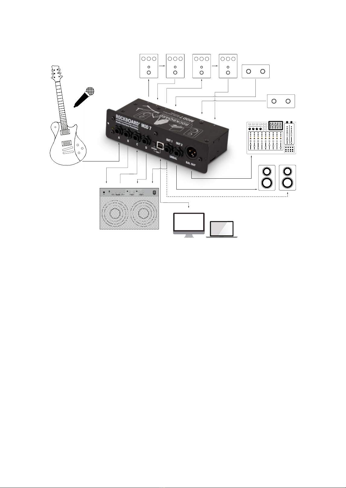
Unbalanced TS Outputs (UNBAL OUT 1/2)
The unbalanced connections UNBAL OUT 1 and UNBAL OUT 2 of the MOD 7 can be used to operate studio
monitors and other active loudspeakers or to send the signal to an amplier. Please note that UNBAL OUT 1 sends
an output signal without a power supply, as well as in bypass mode.
Bypass Function
In order to be able to use the RockBoard® MOD 7 in passive operation even without a power connection, the
patchbay has a passive bypass mode that can be activated either via the BYPASS switch on the front, or via a
latching footswitch. Bypass mode bypasses the active signal splitter and directs the signal from the XLR / 6.3 mm /
/" (TRS) combo input on the back directly to the UNBAL OUT 1 socket on the front.
Footswitchable Bypass and Mute Functions
For a quick and easy access to the bypass and mute functions, the MOD 7 requires a latching double footswitch
with TRS connection. Tip is connected to the mute function, ring is connected to the bypass function, sleeve is
connected to ground. When using a footswitch, the setting of the BYPASS switch on the front panel will be overridden.
Specications
• All-in-One USB Audio Interface Patchbay for Pedalboards
• A/D converter dynamic range: 89 dB
• D/A converter dynamic range: 93 dB
• Supported sampling rates: 44.1 kHz and 48 kHz
• Total Harmonic Distortion (THD): < 0.01% (measured with min. gain)
• Signal to noise ratio: 89 dB
• Frequency range: 50 Hz - 20 kHz (+/- 0.05 dB)
• Fits MOD slots on RockBoard® pedalboards
• Compatible with a wide variety of other pedalboards
• Holds all connections to and from your setup in one place
• Acts as central access point to your eects setup
• Establishes clean cable paths
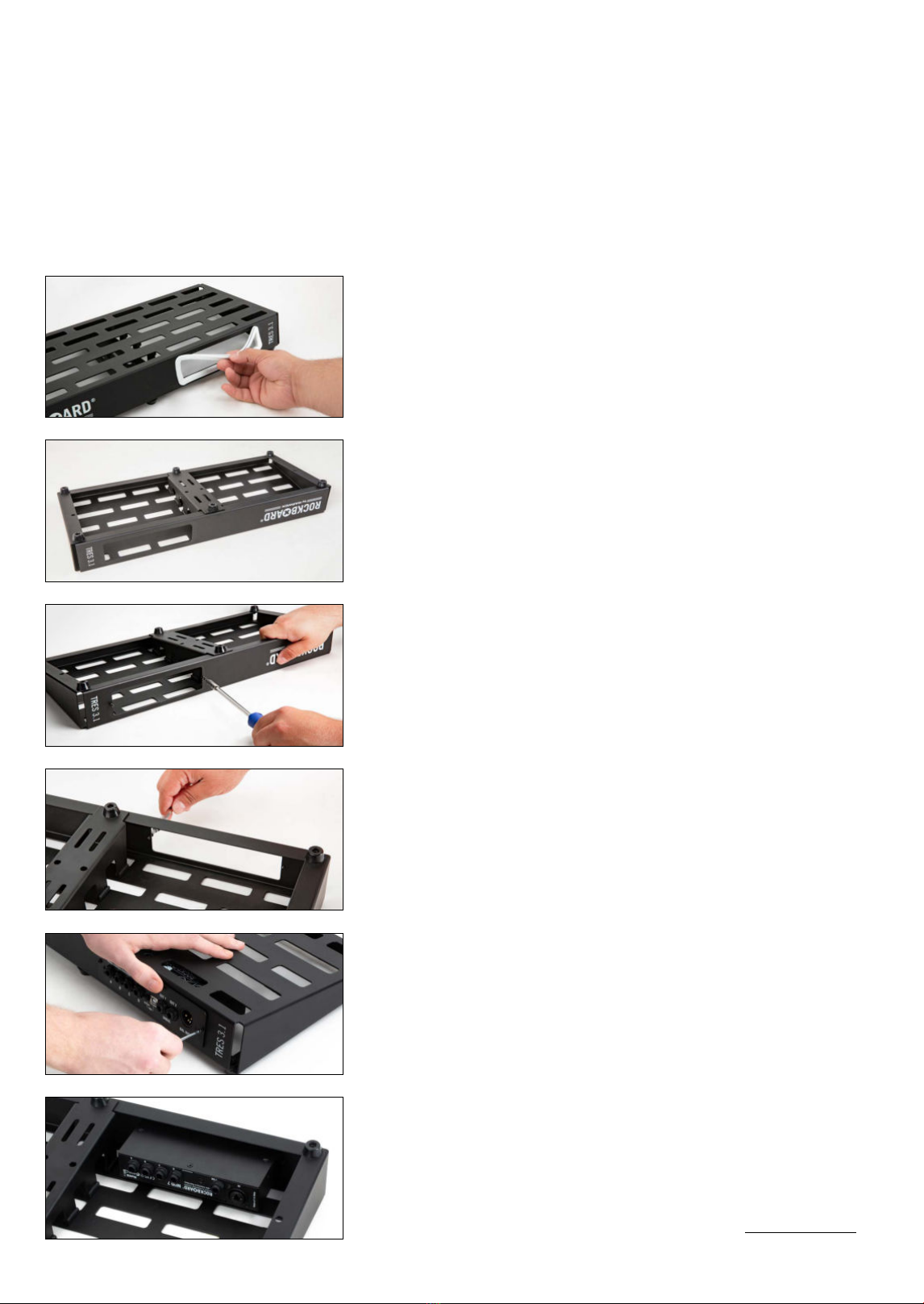
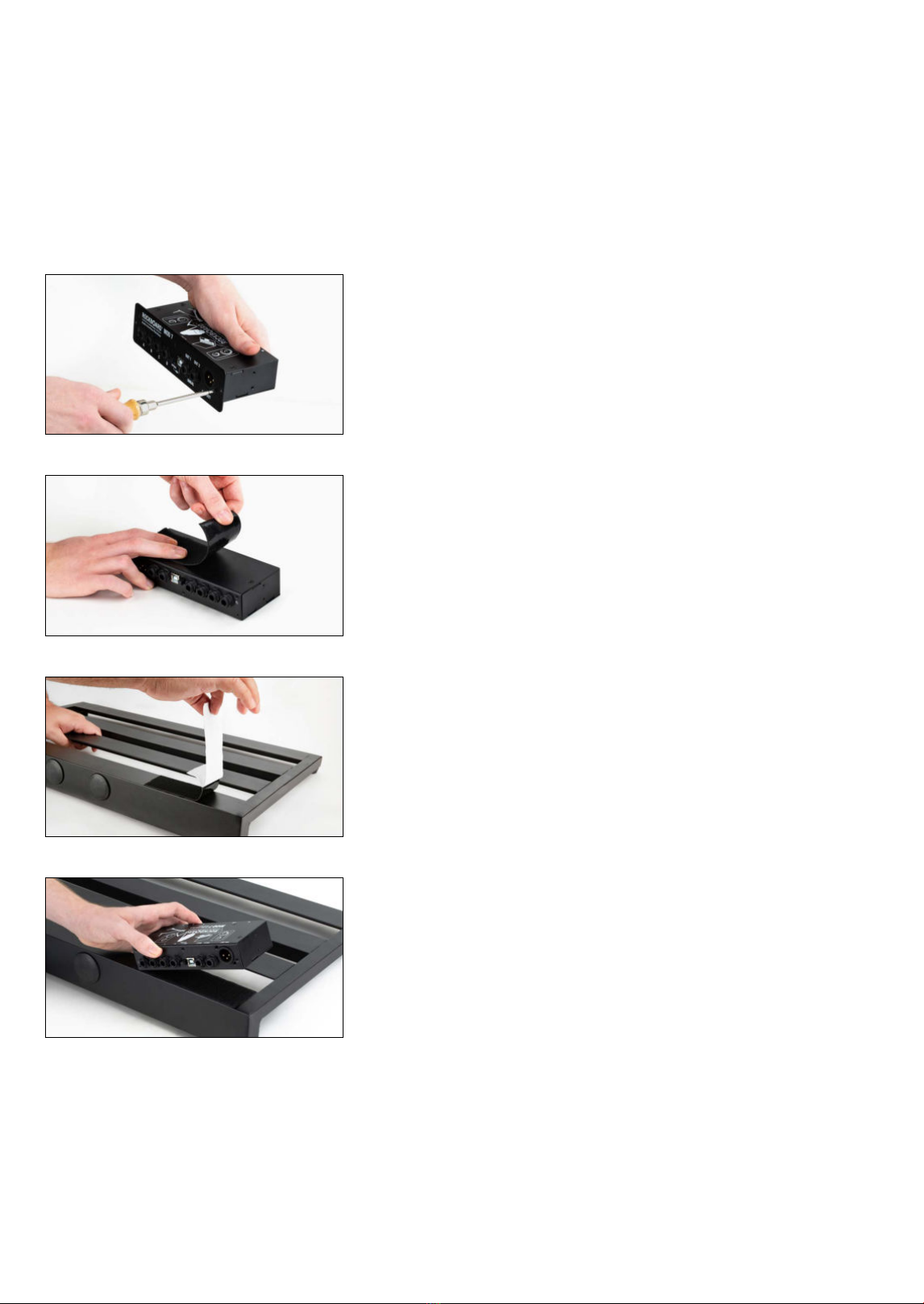
• Detachable front plate for mounting on top or underneath pedalboards
• Includes mounting screws and counter nuts
• Power supply via USB (5V DC)
• Current draw 200 mA
• Dimensions (L x W x H):
175 x 85 x 47 mm / 6 /" x 3 /" x 3 /" (with front plate)
160 x 85 x 33 mm / 6 /" x 3 /" x 1 /" (without front plate)
• Weight:
470 g / 1.04 lbs
• Connections:
4x 6.3 mm / /" stereo thru (TRS)
1x XLR / 6.3 mm / /" (TRS) combo input
1x USB Type B input / output
2x 6.3 mm / /" (TS) unbalanced output
1x XLR balanced output
1x 6.3 mm / /" (TRS) footswitch input
Hinweis: Der Hersteller behält sich das Recht vor, die techn. Daten ohne Vorankündigung zu ändern.