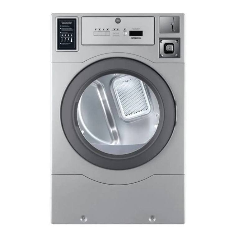
Wascomat D7-290 User manual

Installation manual
Tumble dryer
D7-290
Type N2...
Original instructions
438905403/EN
2023.02.20


Contents
Contents
1 Safety Precautions ..............................................................................................................................5
1.1 Additional safety precautions for gas heated tumble dryer .............................................................7
1.2 General safety information..........................................................................................................7
1.3 Commercial use only..................................................................................................................7
1.4 Copyright ..................................................................................................................................7
1.5 Symbols....................................................................................................................................7
2 Technical data.....................................................................................................................................8
2.1 Drawing ....................................................................................................................................8
2.2 Technical data ...........................................................................................................................9
2.3 Connections ..............................................................................................................................9
3 Setup ...............................................................................................................................................10
3.1 Unpacking...............................................................................................................................10
3.2 Recycling instruction for packaging ........................................................................................... 11
3.3 Siting ......................................................................................................................................12
3.4 Mechanical installation .............................................................................................................12
3.4.1 Securing the machine .....................................................................................................13
4 Marine installation .............................................................................................................................14
5 Reversing the door ............................................................................................................................15
6 Evacuation system ............................................................................................................................18
6.1 Air principle .............................................................................................................................18
6.2 Fresh air..................................................................................................................................19
6.3 Exhaust duct ...........................................................................................................................19
6.4 Shared exhaust duct ................................................................................................................20
6.5 Exhaust dimensioning ..............................................................................................................20
6.6 Adjusting the dryer...................................................................................................................21
7 Steam connection .............................................................................................................................23
7.1 Connecting the steam ..............................................................................................................23
7.2 Steam calorifier........................................................................................................................24
8 Gas connection .................................................................................................................................25
8.1 Fasten the label .......................................................................................................................25
8.2 General...................................................................................................................................25
8.3 Gas installation........................................................................................................................26
8.4 Table of pressure and adjustment..............................................................................................27
8.5 Test run...................................................................................................................................28
8.6 Converting instructions.............................................................................................................28
8.7 Data label................................................................................................................................30
9 Electrical connection..........................................................................................................................31
9.1 Electrical installation ................................................................................................................31
9.2 Single-phase connection ..........................................................................................................31
9.3 Three-phase connection...........................................................................................................32
9.4 Electrical connections ..............................................................................................................33
9.5 Functions for I/O-cards.............................................................................................................34
9.5.1 Central payment (2J) ......................................................................................................34
9.5.2 Central payment (2J) ......................................................................................................35
9.5.3 External coin meter/Central payment (2K) ........................................................................36
9.5.4 Price reduction (2K)........................................................................................................37
9.6 Option.....................................................................................................................................37
9.6.1 External connection 100 mA............................................................................................37
10 At first power up ................................................................................................................................38
10.1 Select language.......................................................................................................................38
10.2 Set time and date.....................................................................................................................38
10.3 Activate/Deactivate the service alarm ........................................................................................38
11 Function check..................................................................................................................................39
12 Disposal information..........................................................................................................................41
12.1 Disposal of appliance at end of life ............................................................................................41
12.2 Disposal of packing..................................................................................................................41
The manufacturer reserves the right to make changes to design and component specifications.



Installation manual 5
1 Safety Precautions
• Servicing shall be carried out only by authorized personnel.
• Only authorized spare parts, accessories and consumables shall be used.
• The machine is not to be used if industrial chemicals have been used for cleaning.
• Do not dry unwashed items in the machine.
• Items that have been soiled with substances such as cooking oil, acetone, alcohol, pet-
rol, kerosene, spot removers, turpentine, waxes and wax removers should be washed
in hot water with an extra amount of detergent before being dried in the machine.
• Items such as foam rubber (latex foam), shower caps, waterproof textiles, rubber
backed articles and clothes or pillows fitted with foam rubber pads should not be dried
in the machine.
• Fabric softeners or similar products should be used as specified by the fabric softener
instructions.
• The final part of a drying cycle occurs without heat (cool down cycle) to ensure that the
items are left at a temperature that ensures that the items will not be damaged.
• Remove all objects from pockets such as lighters and matches.
• WARNING. Never stop the machine before the end of the drying cycle unless all items
are quickly removed and spread out so that the heat is dissipated.
• Adequate ventilation has to be provided to avoid the back flow of gases into the room
for appliances burning other fuels, including open fires.
• Exhaust air must not be discharged into a flue which is used for exhausting fumes from
appliances burning gas or other fuels.
• The machine must not be installed behind a lockable door, a sliding door or a door with
a hinge on the opposite side to that of the machine in such a way that a full opening of
the machine is restricted.
• If the machine has a lint trap this has to be cleaned frequently.
• The lint must not be accumulated around the machine.
• DO NOT MODIFY THIS APPLIANCE.
• When performing service or replacing parts, the power must be disconnected.
• When the power is disconnected, the operator must see that the machine is discon-
nected (that the plug is removed and remains removed) from any point to which he has
access. If this is not possible, due to the construction or installation of the machine, a
disconnection with a locking system in the isolated position shall be provided.
• In accordance with the wiring rules: mount a multi-pole switch prior to the machine to
facilitate installation and service operations.
• WARNING: The appliance must not be supplied through an external switching device,
such as a timer, or connected to a circuit that is regularly switched on and off by a utility.
• If different rated voltages or different rated frequencies (separated by a /) are stated at
the machine data plate, instructions for adjusting the appliance for operation at the re-
quired rated voltage or rated frequency are stated in the installation manual.
• Stationary appliances not fitted with means for disconnection from the supply mains
having a contact separation in all poles that provide full disconnection under overvolt-
age category III, the instructions state that means for disconnection must be incorpo-
rated in the fixed wiring in accordance with the wiring rules.
• The openings in the base, shall not be obstructed by a carpet.

6Installation manual
• Oil-affected items can ignite spontaneously, especially when exposed to heat sources
such as in a tumble dryer. The items become warm, causing an oxidation reaction in
the oil. Oxidation creates heat. If the heat cannot escape, the items can become hot
enough to catch fire. Piling, stacking or storing oil-affected items can prevent heat from
escaping and so create a fire hazard.
• If it is unavoidable that fabrics that contain vegetable or cooking oil or have been conta-
minated by hair care products be placed in a tumble dryer they should first be washed
in hot water with extra detergent – this will reduce, but not eliminate, the hazard.
• Maximum mass of dry cloth: 16.1 kg.
• A-weighted emission sound pressure level at working stations: 70 dB(A).
• Additional requirements for the following countries; AT, BE, BG, HR, CY, CZ, DK, EE,
FI, FR, DE, GR, HU, IS, IE, IT, LV, LT, LU, MT, NL, NO, PL, PT, RO, SK, SI, ES, SE, CH,
TR, UK:
– The appliance can be used in public areas.
– This appliance can be used by children aged from 8 years and above and persons
with reduced physical, sensory or mental capabilities or lack of experience and knowl-
edge if they have been given supervision or instruction concerning use of the appliance
in a safe way and understand the hazards involved. Children shall not play with the ap-
pliance. Cleaning and user maintenance shall not be made by children without
supervision.
• Additional requirements for other countries:
– This appliance is not intended for use by persons (including children) with reduced
physical, sensory or mental capabilities, or lack of experience and knowledge, unless
they have been given supervision or instruction concerning use of the appliance by a
person responsible for their safety. Children should be supervised to ensure that they
do not play with the appliance.

Installation manual 7
1.1 Additional safety precautions for gas heated tumble dryer
• Before installation, check that the local distribution conditions, nature of gas and pres-
sure and the adjustment of the appliance are compatible.
• The machine is not to be installed in rooms containing cleaning machines with per-
chloroethylene, TRICHLOROETHYLENE or CHLOROFLUOROCONTAINING HY-
DROCARBONS as cleaning agents.
• NOTE: it is pointed out that the connection and commissioning of appliances complying
with this standard are subject to observance of the installation regulations in force in
the countries where these appliances are marketed.
• Connection to the appliance shall be made with a flexible hose suitable for the appli-
ance category in accordance with national installation regulations of the country of des-
tination and that in case of doubt the installer shall contact the supplier.
• The appliance should be installed on non-flammable materials for the floor, worktop
and/or wall close to the appliance if required.
• If you can smell gas:
– Do not switch on any equipment
– Do not use electrical switches
– Do not use telephones in the building
– Evacuate the room, building or area
– Contact the person responsible for the machine
1.2 General safety information
In order to prevent damage to the electronics (and other parts) that may occur as the result of condensation, the ma-
chine should be placed in room temperature for 24 hours before being used for the first time.
1.3 Commercial use only
The machine/machines covered by this manual is/are made for commercial and industrial use only.
1.4 Copyright
This manual is intended solely for consultation by the operator and can only be given to third parties with the permis-
sion of Electrolux Professional company.
1.5 Symbols
Caution
Caution, hot surface
Caution, high voltage
Read the instructions before using the machine

8Installation manual
2 Technical data
2.1 Drawing
A
C
1
2
8
B(b)
B(a)
ED
7
6
F
G
HI
3
4
J
K
L
M
N
5
O
fig.7252
1 Operating panel
2 Door opening, ⌀580 mm
3 Electrical connection
4 Gas connection
5 Exhaust connection
6 Steam: in
7Steam: out
A B(a) B(b) C D E
mm 715 1210 1360 1690 740 790
F G H I J K
mm 55 70 365 295 165 140
L M N O
mm 355 605 695 675

Installation manual 9
2.2 Technical data
Weight, net kg 189
Drum volume litres 290
Drum diameter mm 680
Drum depth mm 770
Drum speed, medium load rpm 47
Rated capacity, filling factor 1:18 (Max. load) kg 16.1
Rated capacity, filling factor 1:22 (Recommended. load) kg 13.2
Heating: Electricity kW 18
kW 13.5
Heating: Gas kW 21
Heating: Steam at 600–700 kPa kW 23
Steam pressure kPa 100–1000
Maximum air flow, Electric 50 Hz / 60 Hz m3/h 550 / 550
Maximum air flow, Gas 50 Hz / 60 Hz m3/h 610 / 610
Maximum air flow, Steam 50 Hz / 60 Hz m3/h 690 / 690
Maximum static back pressure, Electric 50 Hz / 60 Hz Pa 400 / 700
Maximum static back pressure, Gas 50 Hz / 60 Hz Pa 400 / 700
Maximum static back pressure, Steam 50 Hz / 60 Hz Pa 600 / 1100
Sound power/pressure level at drying* dB(A) 69/53
Heat emission of installed power, max % 15
* Sound power levels measured according to ISO 60704.
Note!
The default gas appliances are built to run on either GNH or LPG gas where shall be installed at not over than
610 m (2001 ft) high altitude otherwise a kit for high altitude must be installed to the machine.
For the kit No. please refer to the spare parts list.
2.3 Connections
Air outlet ⌀mm 200
Steam inlet/outlet 1” ISO 7/1–R1
Gas connection 1/2” ISO 7/1–R1/2

10 Installation manual
3 Setup
3.1 Unpacking
Note!
Two persons are recommended for the unpacking.
Remove the bolts between the machine and pallet. There are two bolts in the front of the machine and two in the back
of the machine. Remove the lower front panel and remove the two bolts in the front of the machine. Remove the low-
er rear panel and remove the two bolts in the back of the machine.
fig.X00059A
Remove the machine from the pallet.
Note!
When moving the machine, handle it with care. The drum has no transport clamps.
Place the machine on its final position.

Installation manual 11
3.2 Recycling instruction for packaging
4
5
6
7
3
12
fig.X02402
Fig. Description Code Type
1 Wrapping film LDPE 4 Plastics
2 Corner protection PS 6 Plastics
3 Cardboard packaging PAP 20 Paper
4 Pallet FOR 50 Wood
5Screw FE 40 Steel
6 Nut FE 40 Steel
7 Plastic bag PET 1 Plastics

12 Installation manual
3.3 Siting
The figure shows recommended distance to walls and/or other machines.
B
C
A
A
D=C+B
E
F
12
Y
1= Top view
2 = Side view on built in machine
Y = For built-in machines it is recommended that the wall section Y is a removable finish piece. If so, E and F can be 0.
fig.X00959A
A 5–500 mm (Min. 5 mm)
B 500 mm (Min. 200 mm)
C Depth of machine
D D = C + B (Min. 1220 mm to be able to use the machine)
E Min. 20 mm
F Min. 25.4 mm (The overhead soffit may be used to close the gap above the machine. Min. required clearance: 0 mm)
Note!
The machine should be positioned so that there will be enough space for working, both for the user and
service personnel.
Respecting the given recommendations will provide easy access for maintenance and service operations.
In case of space limitations, it is possible to install machines without respecting to the given recommendations. If so,
keep in mind that it might be necessary to disconnect and move other machines to be able to reach and perform
service on affected machine.
3.4 Mechanical installation
Level the machine with the feet of the machine. The maximum height adjustment of the feet is 15 mm.
fig.X02472

Installation manual 13
Remount the panels.
3.4.1 Securing the machine
To ensure steadiness of the machine it is important to fasten the machine to the foundation.
Fasten the four fittings (A) to the foundation using four x M10 set screws (B). If the four fittings are not supplied, order
kit No. 487193545.
Fasten the machine to the fittings.
15.3 mm / 9/16 inch
43.3 mm / 1 11/16 inch
1065 mm / 41 15/16 inch
1005.6 mm / 39 5/8 inch
73 mm / 2 7/8 inch
677.1 mm / 26 5/8 inch
617.6 mm / 24 5/16 inch
45 mm / 1 3/4 inch
A
B
fig.X00120

14 Installation manual
4 Marine installation
To ensure steadiness of the machine it is important to fasten the machine to the foundation.
• Fasten the four clips (A), supplied with the machine, to the foundation. The clips shall be fastened with at least
M10 bolts (B). If the clips are not supplied, order kit No. 487193544.
• Fasten the machine to the clips.
Note!
Marine installation is not applicable for gas heated machines.
15.3 mm / 9/16 inch
43.3 mm / 1 11/16 inch
1065 mm / 41 15/16 inch
1005.6 mm / 39 5/8 inch
73 mm / 2 7/8 inch
677.1 mm / 26 5/8 inch
617.6 mm / 24 5/16 inch
45 mm / 1 3/4 inch
A
B
fig.X00120

Installation manual 15
5 Reversing the door
Disconnect the power to the machine.
Demount the hinges and remove the door. Remove the upper hinge first.
fig.7166
Remove the screws on the front panel and carefully loosen the panel. Push the door switch cable down through the
hole in order to access the cable and then disconnect the cable. Remove the panel.
fig.7548
Move the door switch cable to the opposite side.
Note!
The plastic plug MUST be placed in the hole where the door switch cable was before.
fig.7170

16 Installation manual
Loosen the nuts and move the two brackets to the opposite side.
fig.7171
Move the door switch on the front panel.
1
2
3
4
fig.7172

Installation manual 17
Move the four metal clips from the opposite side.
fig.7174
Connect the door switch cable and push the cable in over the drum and pull it upwards.
fig.7549
Remount the front panel.
Ensure that the door switch cable does not get damaged when remounting the front panel.
Fasten the hinges and mount the door on the opposite side.
Connect the power to the machine.
Test run the machine.

18 Installation manual
6 Evacuation system
6.1 Air principle
The fan creates low pressure in the machine, drawing air into the drum via the heating unit.
The heated air passes through the garments and the drum holes.
The air then flows out through a lint filter positioned below the drum. Then the air is evacuated through the fan and
exhaust system.
Dimension for air evacuation (A) is 200 mm.
A
fig.W00264
Note!
It is very important that the machine gets enough fresh air in order to get the best drying result.

Installation manual 19
6.2 Fresh air
For maximum efficiency and the shortest possible drying time, it is important to ensure that fresh air is able to enter
the room from the outside in the same volume as that is blown out of the room.
To avoid draught in the room it is important to place the air inlet behind the machine.
Provisions for adequate air supply: The area of the air inlet opening should be five times the size of the exhaust pipe
area. The area of the inlet opening is the area through which the air can flow without resistance from the grating/slat-
ted cover.
5 x A
A
fig.7183
Note!
Gratings/slatted covers often block half of the total fresh air vent area. Remember to take this into account.
6.3 Exhaust duct
• Only rigid or flexible metal duct should be used for exhausting.
• Plastic ducting is not to be used.
• Recommended material for exhaust is galvanized steel.
• The duct is not to be assembled with screws or other fastening means that extend into the duct and catch lint.
• The exhaust air should not be vented into a wall, a ceiling, or a concealed space of building.
• The exhaust duct must lead clear of the building as condensation may cause frost damage to the building.
• The exhaust duct must lead to the outdoors.
• The exhaust duct must be placed in such a way that it is protected on the outside.
• The exhaust duct must be smooth on the inside (low air resistance).
• The exhaust duct must have gentle bends.

20 Installation manual
6.4 Shared exhaust duct
It is recommended that each machine is connected to a separate exhaust duct.
When several machines shall use the same exhaust duct the exhaust duct must increase after each machine. The
recommended diameter increase progression is the one in the table.
If several machines are installed on the same exhaust pipe, it is recommended to adjust the airflow on the machines
when all machines are started and running a program with no heat.
Please consider that unnecessarily large ducts create issues with the draught.
fig.W00052
Number of machines 1 2 3 4 5 6 7 8 9 10
Exhaust duct ⌀mm 200 315 400 400 500 500 630 630 630 800
Recommended area
of fresh air intake
m20.16 0.39 0.63 0.63 0.98 0.98 1.56 1.56 1.56 2.51
Minimum area of
fresh air intake
m20.03 0.06 0.09 0.12 0.15 0.18 0.21 0.24 0.27 0.3
The exhaust duct diameter must not be reduced.
6.5 Exhaust dimensioning
It is important that the machine has correct air volume compared to each machines power.
If the air flow is smaller or larger this will result in a longer drying period.
The machine is designed to work with the maximum static back pressure according to the table in the technical data
section.
The exhaust duct must be designed so the static back pressure measured 1 m from the exhaust outlet does not ex-
ceed the maximum allowable back pressure specified in Technical data.
If the outlet pipe is long or the ventilation is not properly designed we recommend to clean the outlet pipes periodi-
cally. Usually, longer ducts need more frequent cleaning.
All cover panels must be mounted in order for the machine to work in the best way.
Table of contents
Other Wascomat Dryer manuals

Wascomat
Wascomat SD-12E User manual

Wascomat
Wascomat CROSSOVER 2.0 Series User manual

Wascomat
Wascomat Gas & Electric Gas & Electric Dryer User manual

Wascomat
Wascomat D7-550 User manual

Wascomat
Wascomat D7-675 User manual

Wascomat
Wascomat D7-190 User manual

Wascomat
Wascomat D7-550 User manual

Wascomat
Wascomat D7-190 User manual

Wascomat
Wascomat D7-675 User manual