Wascomat SD-12E User manual

Installation manual
Tumble dryer
SD–12E, SD–12G
Original instructions
0180500987C/EN
2022.09.02


Contents
Contents
1 Safety Precautions ..............................................................................................................................5
1.1 Gas heated tumble dryer: ...........................................................................................................7
1.2 General safety information..........................................................................................................7
1.3 Commercial use only..................................................................................................................7
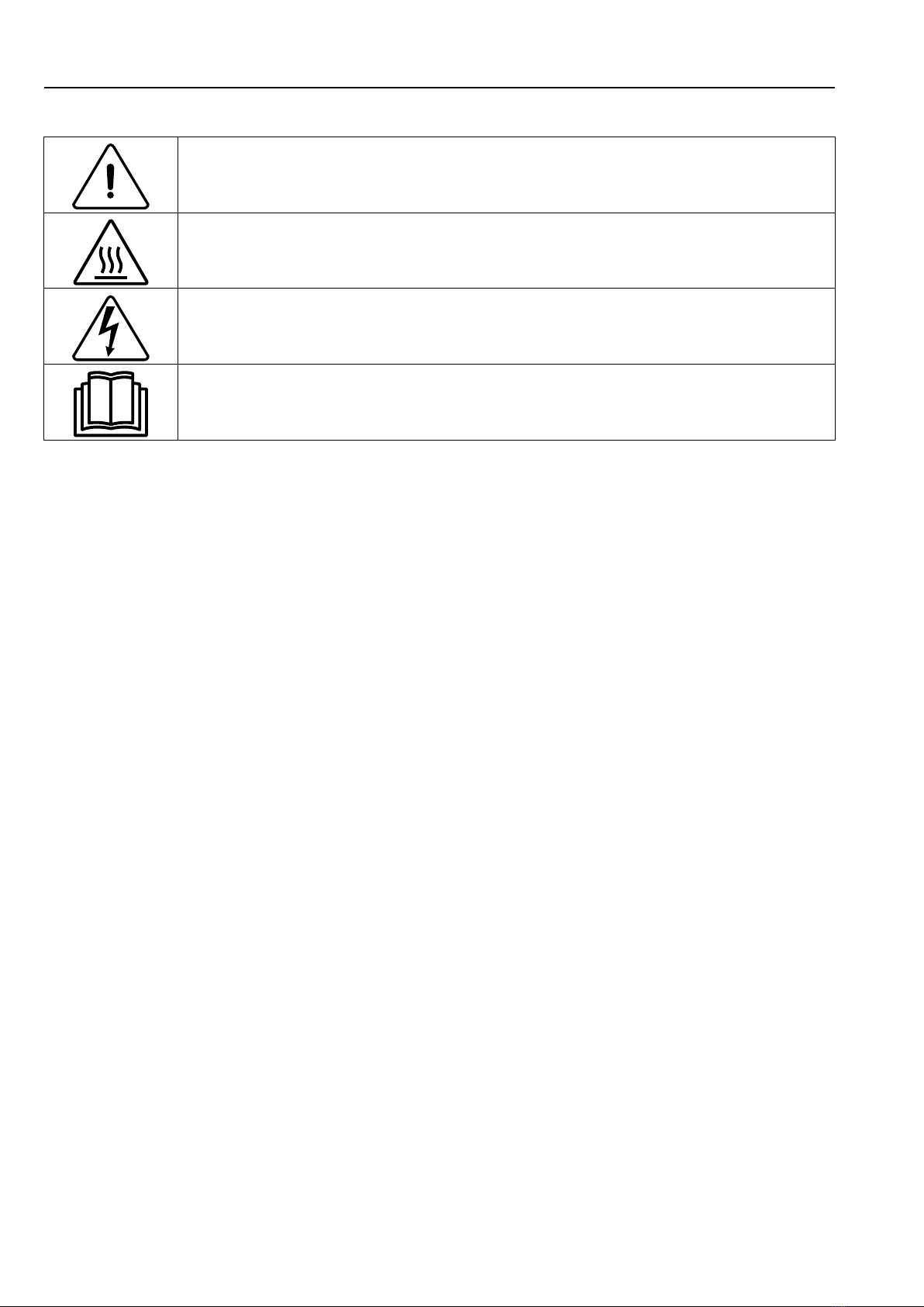
1.4 Symbols....................................................................................................................................8
2 Technical data.....................................................................................................................................9
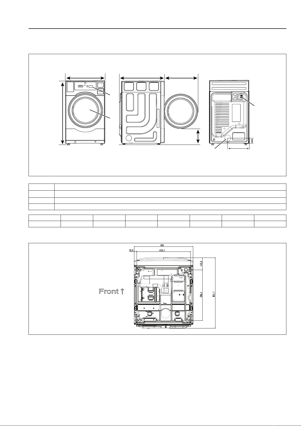
2.1 Drawing ....................................................................................................................................9
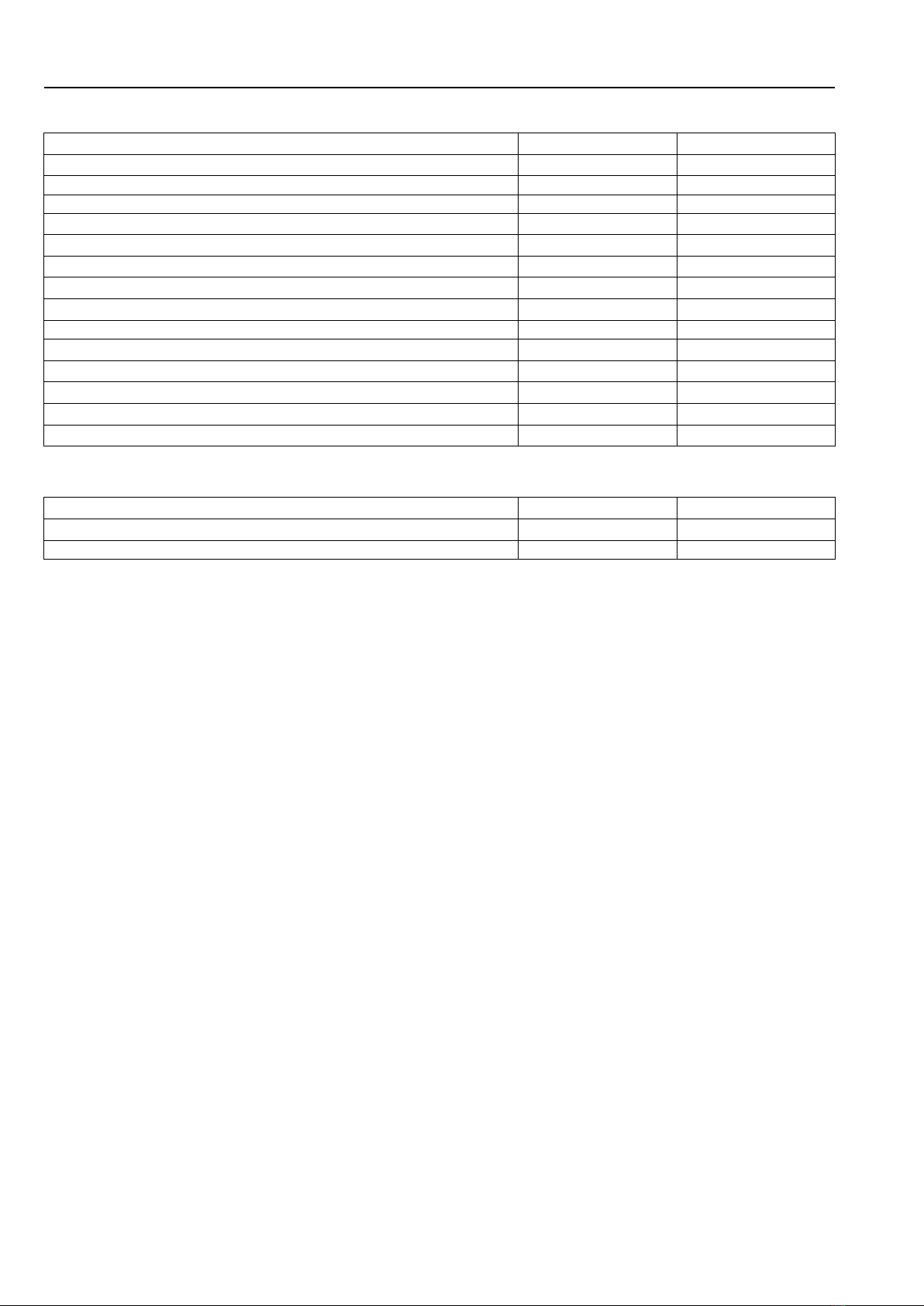
2.2 Technical data .........................................................................................................................10
2.3 Connections ............................................................................................................................10
3 Setup ............................................................................................................................................... 11
3.1 Unpacking............................................................................................................................... 11
3.2 Recycling instruction for packaging ...........................................................................................12
3.3 Siting ......................................................................................................................................13
3.4 Mechanical installation .............................................................................................................14
4 Reversing the door ............................................................................................................................15
5 Evacuation system ............................................................................................................................17
5.1 Air principle .............................................................................................................................17
5.2 Fresh air..................................................................................................................................17
5.3 Exhaust duct ...........................................................................................................................18
5.4 Shared exhaust duct ................................................................................................................18
5.5 Exhaust dimensioning ..............................................................................................................19
5.6 Outside Ductwork Protection.....................................................................................................20
6 Electrical connection..........................................................................................................................21
6.1 Electrical installation ................................................................................................................21
6.2 Single-phase connection ..........................................................................................................22
6.3 Electrical connections ..............................................................................................................22
6.4 Install the Electronic Coin Meter (Coin Operated Models)............................................................23
7 Gas connection .................................................................................................................................25
7.1 Fasten the label .......................................................................................................................25
7.2 General...................................................................................................................................25
7.3 Connect the dryer to the gas supply...........................................................................................26
7.4 Gas installation........................................................................................................................26
7.5 Table of pressure .....................................................................................................................27
7.6 Test run...................................................................................................................................27
7.7 Converting instructions.............................................................................................................27
7.8 Data label................................................................................................................................32
8 Coin meter operation .........................................................................................................................33
8.1 Price Programming & Drying Time Program Setup .....................................................................33
8.2 Free Dry / OPL Mode ...............................................................................................................34
8.3 Price and Time Registers..........................................................................................................34
8.3.1 Time for Amount to Start .................................................................................................34
8.3.2 Time Per Coin (or Push In Free Dry Mode) .......................................................................34
8.4 Promotion programming (for extra drying time)...........................................................................34
8.5 Promotion via the real time clock (RTC) .....................................................................................35
8.6 Promotion via external clock-driven relay or switch .....................................................................35
9 Function check..................................................................................................................................36
10 CPU reset.........................................................................................................................................36
11 Disposal information..........................................................................................................................37
11.1 Disposal of appliance at end of life ............................................................................................37
11.2 Disposal of packing..................................................................................................................37
The manufacturer reserves the right to make changes to design and component specifications.


Installation manual 5
1 Safety Precautions
• Servicing shall be carried out only by authorized personnel.
• Only authorized spare parts, accessories and consumables shall be used.
• The machine is not to be used if industrial chemicals have been used for cleaning.
• Do not dry unwashed items in the machine.
• Items that have been soiled with substances such as cooking oil, acetone, alcohol, pet-
rol, kerosene, spot removers, turpentine, waxes and wax removers should be washed
in hot water with an extra amount of detergent before being dried in the machine.
• Items such as foam rubber (latex foam), shower caps, waterproof textiles, rubber
backed articles and clothes or pillows fitted with foam rubber pads should not be dried
in the machine.
• Fabric softeners or similar products should be used as specified by the fabric softener
instructions.
• The final part of a drying cycle occurs without heat (cool down cycle) to ensure that the
items are left at a temperature that ensures that the items will not be damaged.
• Remove all objects from pockets such as lighters and matches.
• WARNING. Never stop the machine before the end of the drying cycle unless all items
are quickly removed and spread out so that the heat is dissipated.
• Adequate ventilation has to be provided to avoid the back flow of gases into the room
for appliances burning other fuels, including open fires.
• Exhaust air must not be discharged into a flue which is used for exhausting fumes from
appliances burning gas or other fuels.
• The machine must not be installed behind a lockable door, a sliding door or a door with
a hinge on the opposite side to that of the machine in such a way that a full opening of
the machine is restricted.
• If the machine has a lint trap this has to be cleaned frequently.
• The lint must not be accumulated around the machine.
• DO NOT MODIFY THIS APPLIANCE.
• When performing service or replacing parts, the power must be disconnected.
• When the power is disconnected, the operator must see that the machine is discon-
nected (that the plug is removed and remains removed) from any point to which he has
access. If this is not possible, due to the construction or installation of the machine, a
disconnection with a locking system in the isolated position shall be provided.
• In accordance with the wiring rules: mount a multi-pole switch prior to the machine to
facilitate installation and service operations.
• WARNING: The appliance must not be supplied through an external switching device,
such as a timer, or connected to a circuit that is regularly switched on and off by a utility.
• If different rated voltages or different rated frequencies (separated by a /) are stated at
the machine data plate, instructions for adjusting the appliance for operation at the re-
quired rated voltage or rated frequency are stated in the installation manual.
• Stationary appliances not fitted with means for disconnection from the supply mains
having a contact separation in all poles that provide full disconnection under overvolt-
age category III, the instructions state that means for disconnection must be incorpo-
rated in the fixed wiring in accordance with the wiring rules.
• The openings in the base, shall not be obstructed by a carpet.

6Installation manual
• Oil-affected items can ignite spontaneously, especially when exposed to heat sources
such as in a tumble dryer. The items become warm, causing an oxidation reaction in
the oil. Oxidation creates heat. If the heat cannot escape, the items can become hot
enough to catch fire. Piling, stacking or storing oil-affected items can prevent heat from
escaping and so create a fire hazard.
• If it is unavoidable that fabrics that contain vegetable or cooking oil or have been conta-
minated by hair care products be placed in a tumble dryer they should first be washed
in hot water with extra detergent – this will reduce, but not eliminate, the hazard.
• Maximum mass of dry cloth: 12 kg.
• A-weighted emission sound pressure level at working stations: <68 dB(A).
• If the supply cord is damaged, it must be replaced by the manufacturer, its service
agent or similarly qualified persons in order to avoid a hazard.

Installation manual 7
1.1 Gas heated tumble dryer:
• Before installation, check that the local distribution conditions, nature of gas and pres-
sure and the adjustment of the appliance are compatible.
• The machine is not to be installed in rooms containing cleaning machines with per-
chloroethylene, TRICHLOROETHYLENE or CHLOROFLUOROCONTAINING HY-
DROCARBONS as cleaning agents.
• If you can smell gas:
– Do not switch on any equipment
– Do not use electrical switches
– Do not use telephones in the building
– Evacuate the room, building or area
– Contact the person responsible for the machine
• Additional requirements for the following countries; AT, BE, BG, HR, CY, CZ, DK, EE,
FI, FR, DE, GR, HU, IS, IE, IT, LV, LT, LU, MT, NL, NO, PL, PT, RO, SK, SI, ES, SE, CH,
TR, UK:
– The appliance can be used in public areas.
– This appliance can be used by children aged from 8 years and above and persons
with reduced physical, sensory or mental capabilities or lack of experience and knowl-
edge if they have been given supervision or instruction concerning use of the appliance
in a safe way and understand the hazards involved. Children shall not play with the ap-
pliance. Cleaning and user maintenance shall not be made by children without
supervision.
• Additional requirements for other countries:
– This appliance is not intended for use by persons (including children) with reduced
physical, sensory or mental capabilities, or lack of experience and knowledge, unless
they have been given supervision or instruction concerning use of the appliance by a
person responsible for their safety. Children should be supervised to ensure that they
do not play with the appliance.
1.2 General safety information
In order to prevent damage to the electronics (and other parts) that may occur as the result of condensation, the ma-
chine should be placed in room temperature for 24 hours before being used for the first time.
1.3 Commercial use only
The machine/machines covered by this manual is/are made for commercial and industrial use only.

8Installation manual
1.4 Symbols
Caution
Caution, hot surface
Caution, high voltage
Read the instructions before using the machine

Installation manual 9
2 Technical data
2.1 Drawing
2
4
3
1
C
A
D
B E
G
F
fig.W01608
1 Operating panel
2 Door opening, ⌀570 mm
3 Electrical connection
4 Exhaust connection
A B C D E F G
mm 686 822 1098 302 555 91 368
Footprint
fig.X02473

10 Installation manual
2.2 Technical data
Net Weight(electric heating)kg 70
Net Weight(Gas heating)kg 78
Drum volume litres 218
Drum diameter mm 664
Drum depth mm 533
Drum speed, medium load rpm 45
Rated capacity, filling factor 1:18 (Max. load) kg 12
Heating: Electricity(230V)kW 4.84
Nominal Heat Input (Gas dryer)kW 5.7
Maximum air flow m3/h 256
Maximum static back pressure Pa 130
A-weighted emission sound pressure level at working stations dB(A) 68
Gas rate(Hi):G20 m3/h 0.6
Gas rate(Hi):G30 m3/h 0.17
Gas rate(Hi):G31 m3/h 0.23
2.3 Connections
Air outlet(Electric heating)⌀mm 100
Air outlet(Gas heating)⌀mm 102
Gas connection 1/2” ISO 7/1–R1/2
Note!
It is pointed out that the connection and commissioning of appliances complying with this standard are sub-
ject to observance of the installation regulations in force in the countries where these appliances are
marketed.

Installation manual 11
3 Setup
3.1 Unpacking
Note!
Two persons are recommended for the unpacking.
The machine is delivered fixed onto the transport pallet with packing strap.
Remove packing strap from the machine then remove the transport pallet.
Remove all the packing from the machine.
Note!
When moving the machine, handle it with care. The drum has no transport clamps.
Place the machine on its final position.

12 Installation manual
3.2 Recycling instruction for packaging
3
1
2
4
5
6
7
8
9
10
11
fig.X02415
Fig. Description Code Type
1 Cardboard packaging PAP 20 Paper
2 Packaging box sticker PAP 22 Paper
3 Bar code sticker PAP 22 Paper
4 Wrapping film HDPE 2 Plastics
5 Front corner protection PS 6 Plastics
6 Back corner protection PS 6 Plastics
7 Top protection PS 6 Plastics
8 Bottom protection C/* 81 Combination
9 Pallet FOR 50 Wood
10 PET tape PET 1 Plastics
11 Packaging strap PP 5 Plastics

Installation manual 13
3.3 Siting
The machine should be positioned so that there is plenty of room for working, both for the user and service personnel.
The following clearances are recommended:
• The requirement to allow the door to open completely is 36 inches (91 cm).
• A minimum overhead clearance of 6-inches (15.24 cm) is recommended.
• Dryer should be positioned a minimum of 12-inches (30.5 cm) away from the nearest obstruction, 24-inches (61
cm) is recommended for ease of installation, maintenance, and service.
A
B
C
fig.W01609
A Min. 36 inch (91 cm)
B Min. 6 inch (15.24 cm)
C Min. 12 inch (30.5 cm)

14 Installation manual
3.4 Mechanical installation
Level the machine with the feet of the machine. The maximum height adjustment of the feet is 15 mm.
It is important to lock the feet with nuts (A).
For the gas dryer, the four feet should be locked with the expansion bolts and foot press plates in the accessory bag
to prevent straining of the gas supply when the appliance is moved, at least the two diagonal feet should be fixed.
See the top right Illustration. If the installation conditions are not suitable for the use of expansion bolts, it is also pos-
sible to use a rope to straighten the machine onto the fixed pile on the wall.
A
fig.W01610

Installation manual 15
4 Reversing the door
Disconnect the power to the machine.
Demount the hinge and remove the door.
fig.W01611
Demount the screws on the door module except for (A) and (B). Rotate back door plate parts (C) and the middle
frame (D) by 180 degrees. Remount the screws on the door module.
CA
B
D
fig.W01612

16 Installation manual
Demount the two magnets (A) and the protective cover (B) and move them to the opposite side.
A
B
AB
fig.W01613
Remount the two magnets (A) and the protective cover (B).
Remount the door on the opposite side and fasten the hinges.
fig.W01614
Connect the power to the machine.
Test run the machine.

Installation manual 17
5 Evacuation system
5.1 Air principle
The fan creates low pressure in the machine, drawing air into the drum via the heating unit.
The heated air passes through the garments and the drum holes.
The air then flows out through a lint filter positioned below the drum. Then the air is evacuated through the fan and
exhaust system.
fig.W01615
Note!
It is very important that the machine gets enough fresh air in order to get the best drying result.
5.2 Fresh air
For maximum efficiency and the shortest possible drying time, it is important to ensure that fresh air is able to enter
the room from the outside in the same volume as that blown out of the room.
To avoid draught in the room it is important to place the air inlet behind the machine.
The area of the air inlet opening is recommended to be five times the size of the exhaust pipe area. The area of the
inlet opening is the area through which the air can flow without resistance from the grating/slatted cover.
fig.W01616
Note!
Gratings/slatted covers often block half of the total fresh air vent area. Remember to take this into account.

18 Installation manual
5.3 Exhaust duct
• Only rigid or flexible metal duct should be used for exhausting.
• Plastic ducting is not to be used.
• Recommended material for exhaust is galvanized steel.
• The duct is not to be assembled with screws of other fastening means that extend into the duct and catch lint.
• The exhaust air should not be vented into a wall, a ceiling, or a concealed space of building.
• The exhaust duct must lead clear of the building as condensation may cause frost damage to the building.
• The exhaust duct must lead to the outdoors.
• The exhaust duct must be placed in such a way that it is protected on the outside.
• The exhaust duct must be smooth on the inside (low air resistance).
• The exhaust duct must have gentle bends.
fig.W01617
5.4 Shared exhaust duct
It is recommended that each machine is connected to a separate exhaust duct and fully inserts into the exhaust
duct.
When several machines shall use the same exhaust duct , the exhaust duct must increase after each machine.
fig.W01618

Installation manual 19
Number of
machines
1 2 3 4 5 6 7 8 9 10
Exhaust duct ⌀mm 100 200 300 300 400 400 500 500 600 600
Recommended
area of fresh air
intake
m20.04 0.16 0.35 0.35 0.63 0.63 0.98 0.98 1.41 1.41
Minimum area of
fresh air intake
m20.03 0.117 0.223 0.31 0.351 0.468 0.585 0.702 0.846 1.17
The exhaust duct diameter must not be reduced.
The multiple dryers must have separate backdraft dampers when connected through a shared exhaust duct.
If not, the load in the dryer will be affected by other dryers and become moist.
5.5 Exhaust dimensioning
It is important that the machine has correct air volume compared to each machines power. If the air flow is smaller or
larger this will result in a longer drying period.
If the outlet pipe is long or the ventilation is not properly designed we recommend to clean the outlet pipes periodi-
cally. The exhaust pipes shall be short in order for the machine to work in the best way.
Failure to install back draft dampers in shared dryer exhaust ducts can cause hazardous conditions such backflow
of combustible gases. Single or independent dryer venting is recommended. It is suggested that the use of 90° turns
be avoided; use 30° and/or 45° bends.
It is recommended that exhaust or booster fans not be used in the exhaust ductwork system. If an exhaust booster
fan is required, care must be taken to meet all other installation requirements.
The exhaust duct must be designed the static back pressure measured from the exhaust outlet connection does not
exceed the maximum allowable back pressure specified in Technical data.
Note!
1. The flue outlet of gas dryer shall be female and shall allow connection to a flue duct whose diameter com-
plies with the standards in force in the country where the appliance is to be installed.
2. When installing the exhaust duct of the gas dryer, keep a certain angle with the vertical wall so that any
condensate formed when operating the appliance from cold can be discharged.
3. The connection where the exhaust duct connects to the dryer should be sealed with steel clamp or duct
tape to prevent escaping the combustion products from the machine.
4. For gas dryer, vertical venting is prohibited.
87°
fig.W01619

20 Installation manual
5.6 Outside Ductwork Protection
To protect the outside end of the horizontal ductwork from the weather, a 90° elbow bent downward should be in-
stalled where the exhaust exits the building. If the ductwork travels vertically up through the roof, it should be pro-
tected from the weather by using a 180° turn to point the opening downward. In either case, allow at least twice the
diameter of the duct between the duct opening and the nearest obstruction.
Important
Do not use screens, louvers, or caps on the outside opening of the exhaust ductwork.
This manual suits for next models
1
Table of contents
Other Wascomat Dryer manuals

Wascomat
Wascomat D7-675 User manual

Wascomat
Wascomat D7-290 User manual

Wascomat
Wascomat D7-190 User manual

Wascomat
Wascomat Gas & Electric Gas & Electric Dryer User manual

Wascomat
Wascomat D7-550 User manual

Wascomat
Wascomat D7-190 User manual

Wascomat
Wascomat CROSSOVER 2.0 Series User manual

Wascomat
Wascomat D7-675 User manual

Wascomat
Wascomat D7-550 User manual
Popular Dryer manuals by other brands

Asko
Asko T208CW installation instructions

Maytag
Maytag MLE27PD User instructions

LG
LG TROMM DLE59555W User's guide & installation instructions

Russell Hobbs
Russell Hobbs RH3VTD800 instruction manual

Siemens
Siemens WT47X940EU Installation and operating instructions

Whirlpool
Whirlpool SDRY60 Operation manual