Wassp WMB-X230 User manual

TRANSDUCER INSTALLATION MANUAL
V2.6

Page 2 of 34 Page 3 of 34Doc: Transducer Installation
Version: 2.6 May 2021
Doc: Transducer Installation
Version: 2.6 May 2021
wassp.com wassp.com
TRANSDUCER INSTALLATION MANUALTRANSDUCER INSTALLATION MANUAL
SUPPORT INFORMATION
For details on Registration, Support and Resources see "10 Product Registration, Support
and Resources" on page 32.
WARNINGS, CAUTIONS AND NOTES
Warnings, cautions and notes are indicated by the following icons throughout this
manual:
WARNING indicates that if the instruction is not heeded, the action may result
in loss of life or serious injury.
CAUTION indicates that if the instruction is not heeded, the action may result
in equipment damage or software corruption.
NOTE indicates a TIP or additional information that can be helpful while
performing a procedure.
WASSP TRANSDUCER
INSTALLATION MANUAL
This installation manual covers the installation recommendations for the WASSP 160kHz,
WASSP 80kHz and WASSP Wideband Fairing Transducer 90-190kHz.
This manual does not cover installation and setup of any associated WASSP system
components.
DOCUMENT REVISION HISTORY
REVISION DATE REASON FOR CHANGE VERSION
April 2016 Compilation 1.0
June 2016 Added Technical Specification and updates 1.1
June 2017 Corrected typos in Figures 3 & 4 and Section 4 1.2
July 2017 Update Section 5.2 Mounting the Cable Gland 2.0
August 2017 Addition of Ceramic Discharge Procedure 2.1
December 2017 Update Section 8 Technical Specifications 2.2
May 2019 Update Section 7 Cable Connection to DRX 2.3
February 2020 Added Section 6 Fairing Installation 2.4
May 2020 Update Wideband Fairing Transducer 90-190kHz 2.5
May 2021 Update Dimensions setion 2.1, 2.2 and 7.1 2.6
RELATED DOCUMENTS
»WMB-X230 Installation Manual
»WMB-3250 Installation Manual
»WASSP DRX Installation Manual
Further documentation and updated specifications and installation manuals can be found
at wassp.com
GENERAL NOTICES
WASSP Ltd. reserves the right to change the contents of this manual and any system
specifications without notice.
Contact WASSP Ltd. regarding copying or reproducing this manual.
SAFETY NOTICES
The installer of the equipment is solely responsible for the correct installation of the
equipment. WASSP Ltd. holds no responsibility for any damage associated with incorrect
installation.

Page 4 of 34 Page 5 of 34Doc: Transducer Installation
Version: 2.6 May 2021
Doc: Transducer Installation
Version: 2.6 May 2021
wassp.com wassp.com
TRANSDUCER INSTALLATION MANUALTRANSDUCER INSTALLATION MANUAL
CONTENTS
1 Introduction 6
2 Transducer Dimensions 7
2.1. 160kHz Transducer 7
2.2. 80kHz Transducer 8
2.3. Wideband Fairing Transducer 90-190kHz 9
3 Mounting Options 10
3.1. Through Hull Mounting 10
3.2. Pole Mounting 11
4 Hull Mounting Considerations 12
5 Mounting Assembly 14
5.1. 160kHz Transducer Mounting 14
5.2. 80kHz Transducer Mounting Assembly 16
5.3. Wideband Fairing Transducer 90-190kHz MOUNTING 19
6 WASSP Wideband Fairing Transducer 90-190kHz Installation 20
6.1. Measure and preparation 21
6.2. Mounting the fairing 22
6.3. Fairing Installation 23
6.4. TRANSDUCER Installation 24
7 Cable Installation 25
7.1. Gland Assembly 25
7.2. Mounting the Cable Gland 25
7.3. Transducer Cable 28
7.3.1. Replacing / Repairing an RJ-45 Connector29
8 Cable Connection to DRX 30
9 Technical Specification 32
10 Product Registration, Support and Resources 32
FIGURES
Figure 1. 160kHz Transducer Dimensions 7
Figure 2. 80kHz Transducer Dimensions 8
Figure 3. Wideband Fairing Transducer 90-190kHz Dimensions 9
Figure 4. Through Hull Transducer Mounting 10
Figure 5. Positioning the Transducer on the Vessel Hull 10
Figure 6. Pole Transducer Mounting 11
Figure 7. Transducer mounting locations for larger displacement hulls 13
Figure 8. Alloy / Plastic Gland Assembly Outline and Dimensions 25
Figure 9. Steel Gland Assembly Outline and Dimensions 25
Figure 10. Mounting the Gland Assembly 26
Figure 11. Gland nut travel measurement point for acetal and aluminium glands 27
Figure 12. Gland nut travel measurement point for steel glands 27
Figure 13. Gland Assembly - Cable Connectors 28
Figure 14. DRX with the Transducer Receive Discharge cover label instruction 30
Figure 15. Ceramic Discharge Module 30
Figure 16. Discharging Transducer Channels 31

Page 6 of 34 Page 7 of 34Doc: Transducer Installation
Version: 2.6 May 2021
Doc: Transducer Installation
Version: 2.6 May 2021
wassp.com wassp.com
TRANSDUCER INSTALLATION MANUALTRANSDUCER INSTALLATION MANUAL
1 INTRODUCTION
The WASSP system supports several dierent transducer types intended to be either pole,
keel, thru hull or tank mounted. Finite measurements and fabrication should be based on
the physical transducer to allow for manufacturing tolerances.
The transducer is supplied standard with a 10m cable. Dierent cable lengths such as 5m
and 20m are available. Please ask your WASSP representative for more details.
Pocket mount Transducers
The WASSP 160kHz and WASSP 80kHz transducers are rectangular-shaped transducer for
keel and tank/pocket mounting, encased in a sealed sea chest. A sea chest for housing
and sealing the transducer should be designed and constructed by a reputable shipyard
to suit the size and contours of the hull of each individual vessel.
This must be sized and constructed accurately. The sea chest provides a stable platform
for the transducer and must be mounted as horizontal to the vessel’s waterline as
possible.
A WASSP gland in alloy, plastic or steel are available for the the transducer cable through-
hull seal.
Thru-Hull Transducer
The WASSP Wideband Fairing Transducer 90-190kHz is available with a fairing that can be
cut into a suitable shape for the hull of the ship with a dead rise of up to 30 degrees.
The Fairing Transducer 90-190kHz can allow WASSP operation at up to 20kn (installation
dependant). The maximum vessel speed to be performed is 40 kn.
This transducer can also be used for a pole mount solution.
This Manual covers the following transducers:
»WASSP 160 kHz
»WASSP 80 kHz
»WASSP Wideband Fairing Transducer 90-190kHz (WSP-503-160-10)
2 TRANSDUCER DIMENSIONS
The following drawings give the overall dimensions of the WASSP Transducer. The
recommended cut-out dimensions for a mounting plate are also shown. Final cut-out
dimensions should be based on actual transducer measurement..
2.1. 160KHZ TRANSDUCER
Figure 1. 160kHz Transducer Dimensions

Page 8 of 34 Page 9 of 34Doc: Transducer Installation
Version: 2.6 May 2021
Doc: Transducer Installation
Version: 2.6 May 2021
wassp.com wassp.com
TRANSDUCER INSTALLATION MANUALTRANSDUCER INSTALLATION MANUAL
2.2. 80KHZ TRANSDUCER
Figure 2. 80kHz Transducer Dimensions
2.3. WIDEBAND FAIRING TRANSDUCER 90190KHZ
15.40
32.70
392
A A
524
176.50
110.50
166.50
85.50
52
SECTION A-A
REV.
DESCRIPTION
DATE
UPDATED BY
CHECKED BY
01
INITIAL RELEASE
30-01-2020
ALEXANDRA OETZEL
CRAIG SHANNON
GENERAL TOLERANCES UNLESS OTHERWISE SPECIFIED (MEDIUM)
≤3
>3-6
>6-30
>30-120
>120-400
>400-1000
>1000-2000
0.1 0.1 0.2 0.3 0.5 0.8 1.2 1.0
GENERAL TOLERANCES UNLESS OTHERWISE SPECIFIED (FINE)
≤3
>3-6
>6-30
>30-120
>120-400
>400-1000
>1000-2000
0.05 0.05
0.1
0.15
0.2 0.3 0.5 0.5
GENERAL TOLERANCES UNLESS OTHERWISE SPECIFIED (COARSE)
≤3
>3-6
>6-30
>30-120
>120-400
>400-1000
>1000-2000
0.2 0.3 0.5 0.8 1.2 2.0 3.0 2.0
F
E
4
2
17
5
38
6
B
C
D
A
1 OF 1
A3
CHECKED BY
DESCRIPTION
PART NUMBER
REVISION
DRAWN BY
As Parts
MATERIAL
Transducer ASM
SHEET
SIZE
DATE
200691
30-01-2020
Alexandra Oetzel
Craig Shannon
B
C
D
E
F
A
18
67
5
4
3
2
GENERAL NOTES:
PART MUST BE CLEAN WITH NO SINKS, FLASH, SHARP EDGES OR BURRS.
1.
ALL DIMENSIONS ARE IN MILLIMETRES UNLESS OTHERWISE SPECIFIED.
2.
ALL DIMENSIONS AND TOLERANCES TO APPLY AFTER FINAL TEXTURING
3.
AND SURFACE FINISHING.
REFER TO CAD DATA FILE (200691.IGES/.STEP/.X_T) FOR MISSING
4.
DIMENSIONS.
UNLESS OTHERWISE STATED, ONLY USE RoHS COMPLIANT MATERIAL.
5.
This document contains confidential and proprietary information and rights that belongs to Electronic Navigation Ltd. Using, or permitting the use of, any of the information
contained herein, copying or imaging all or part of this document by any means, or permitting any such copying or imaging, or disclosing, or permitting the disclosure of,
any of its content to third parties is strictly forbidden without express written consent of Electronic Navigation Ltd. ©2019 Copyright Electronic Navigation Ltd.
CLIENT
Electronic
Navigation
FINISH
As Parts
COLOUR
As Parts
IF YOU OVERRIDE DIMESNIONS OR LINKS PLEASE MAKE A NOTE OF THIS OFF SHEET
STANDARD DRAWING NOTES (DELETE/ADD AS NEEDED):
PLASTIC PARTS:
SHEET METAL PARTS:
NOTES UNLESS OTHERWISE SPECIFIED:
NOMINAL DRAFT ANGLE: XX°
1.
NOMINAL WALL THICKNESS: XXmm
2.
ALLOWABLE FLASH: ±X.XXmm
3.
TRIM GATE: ±X.XXmm
4.
EJECTOR MARKS: ±X.XXmm
5.
CORNERS MOUDLED SHARP: RX.X MAX
6.
PART IDENTIFICATION:
7.
a. MOLD CAVITY NUMBER: 0.15mm RAISED
b. PART NUMBER: 0.15mm RAISED
c. PLASTIC GENERIC IDENTIFIER THIS AREA:
i. “PC/ABS”, FONT: ARIAL, 3mm HEIGHT, 0.15mm RAISED
ii. SPI ‘TRIANGULAR’ RESIN IDENTIFICATION CODE: 1… 7
d. DATE WHEEL FOR MONTH / YEAR
MACHINED PARTS:
NOTES UNLESS OTHERWISE SPECIFIED:
1.
NOTES UNLESS OTHERWISE SPECIFIED:
1.
NOTES UNLESS OTHERWISE SPECIFIED:
1.
ASSEMBLIES:
Figure 3. Wideband Fairing Transducer 90-190kHz Dimensions

Page 10 of 34 Page 11 of 34Doc: Transducer Installation
Version: 2.6 May 2021
Doc: Transducer Installation
Version: 2.6 May 2021
wassp.com wassp.com
TRANSDUCER INSTALLATION MANUALTRANSDUCER INSTALLATION MANUAL
3 MOUNTING OPTIONS
3.1. THROUGH HULL MOUNTING
When mounting the transducer, ensure it is accurately running parallel to the keel. See
below.
WASSP
Transducer
WASSP
Transducer
120°
Beam
Angle
300 meters
100 meters
Depth
Avoid mounting another transducer in the vicinity
of the WASSP Transducer, especially along the line of the beam.
VIEWED FROM ABOVE
Location must be such that
beam is clear of hull.
Figure 4. Through Hull Transducer Mounting
AFT
90°
Transducer
90°
90°
FORWARD
HORIZONTAL PLANE
Keel
Looking from above (not to scale)
Mounting Brackets
Figure 5. Positioning the Transducer on the Vessel Hull
CAUTION: The above mounting example is provided as a guide. WASSP Ltd.
recommend that a reputable boat builder is used to install the transducer to
prevent damage to the vessel’s hull.
3.2. POLE MOUNTING
The transducer can be used with a temporary mounting assembly. The assembly would
typically incorporate transducer, and a position and motion sensor, and be deployed on
a rigid mount over the side or the stern of the vessel such that it can be raised / lowered
when required.
AFT
90°
90°
90°
FORWARD
HORIZONTAL PLANE
Keel
Looking from above (not to scale)
GPS
Transducer
Figure 6. Pole Transducer Mounting
CAUTION: The above mounting example is provided as a guide. WASSP
Ltd. recommend that a reputable boat builder is used to fabricate the pole
mount assembly.
Any flex in the pole mount during operation will introduce errors.

Page 12 of 34 Page 13 of 34Doc: Transducer Installation
Version: 2.6 May 2021
Doc: Transducer Installation
Version: 2.6 May 2021
wassp.com wassp.com
TRANSDUCER INSTALLATION MANUALTRANSDUCER INSTALLATION MANUAL
4 HULL MOUNTING CONSIDERATIONS
The transducer is mounted on the hull below the water line, normally using a permanent
sea chest. The transducer must be mounted so that it is aligned with the fore-aft axis of
the vessel. It must also be mounted so that the flat underside of the transducer is as close
to horizontal as possible.
If the vessel has a keel, the transducer can be mounted somewhere along the length of
it. If it is mounted on the hull, it should be far enough away from the keel so that the keel
will not be detected within the 120° WASSP beam pattern. Figure 4 on page 10 shows
a sea chest type through-hull mounting designed specifically for a fast moving, alloy hull
crayfish boat.
The performance of the system is directly related to the mounting location of the
transducer, especially for high-speed cruising. The installation should be planned in
advance, keeping in mind the fixed cable length of your transducer (5m / 10m / 20m)
and the following factors:
»Air bubbles and turbulence caused by movement of the vessel seriously degrade the
sounding capability of the transducer. The transducer should be located in a position
with the smoothest water flow.
»The transducer should not be mounted close to propellers because noise from
propellers can adversely aect the performance of the transducer.
»Mount the transducer inboard of lifting strakes as these create acoustic noise.
»The transducer must always remain submerged, even when the boat is rolling,
pitching or planing at high speed.
»A practical choice would be somewhere between a 1/3 and a 1/2 of the boat’s
length from the bow. For planing hulls, a practical location is generally towards the
rear of the vessel, to ensure that the transducer is always submerged, regardless of
the planing angle.
»Do not mount another transducer near the WASSP transducer as it will cause
interference
Planing hulls
On planing hulls the transducer needs to be mounted in or on the aft part of the hull,
which stays in the water when the vessel is on the plane.
The transducer can be mounted either in a streamlined housing or blister on the hull or
inside the hull in a specially prepared coerdam, with the transducer face flush with the
hull and faired to the hull shape.
It is important that the part of the hull in front of the transducer is smooth and has no hull
penetrations or attachments of any kind.
Displacement hulls
A practical choice is somewhere in the area between a ⁄ and a ⁄ of the vessel’s length,
from the bow. The transducer should be mounted in a housing or blister attached to the
hull.
The disturbed aerated water tends to be in a layer against the hull, it’s thickness varies by
vessel’s speed and sea conditions. Therefore the deeper the housing is, i.e. the further
the transducer is away from the hull, the better the equipment will perform. Also on
V-shaped hulls the housing should be mounted against or close to the keel, again to get
deeper and away from aeration and turbulence. The 120 WASSP beam pattern must be
kept in mind when mounting the transducer. No part of the keel or hull should protrude
into this pattern.
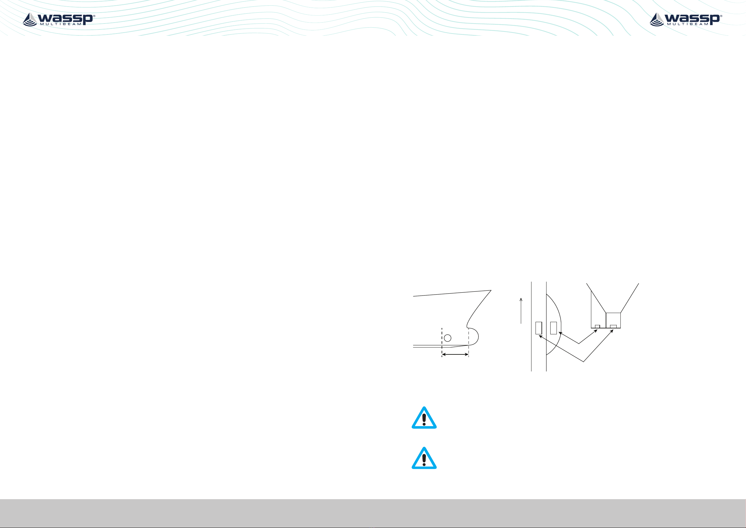
Larger displacement hulls with bow thruster
The best location on these vessels is in or against the keel, forward of a line just aft of the
thruster cavity. Locations further aft are becoming heavily aected by aeration when the
vessel pitches and air exhausts out of the thruster tunnel on the downward movement
of the bow. This air creates havoc with the performance of any transducers further aft on
the hull. "Figure 7. Transducer mounting locations for larger displacement hulls" suggest
mounting locations for these types of vessels.
In these installations, the strength of the mounting becomes very important, as the
transducer can be out of the water when the vessel pitches. Re-entry into the water
exerts large forces on the transducer face and the mounting structure.
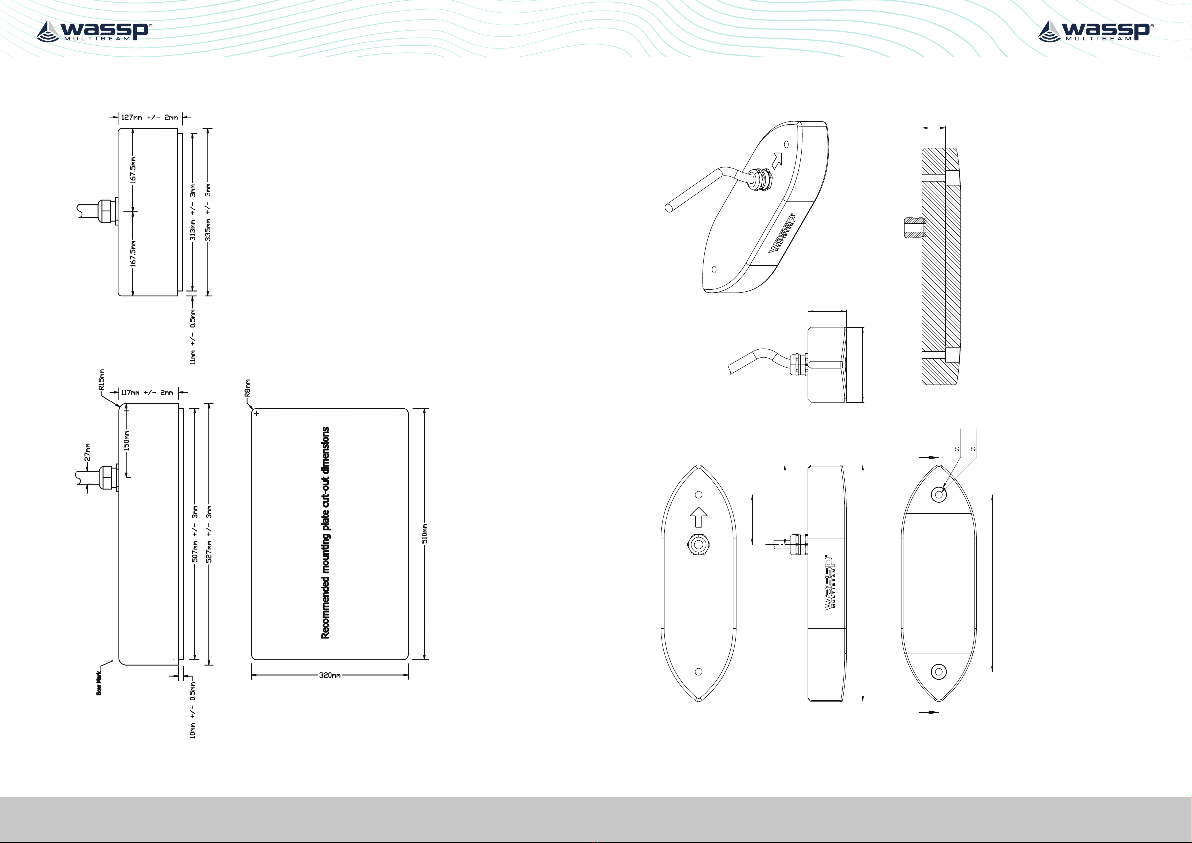
See "5.1. 160kHz Transducer Mounting" on page 14 and "5.2. 80kHz Transducer
Mounting Assembly" on page 16 for mounting diagrams and instructions. These steps
must be carried out accurately and completely.
FW D
Viewfrom above
In housing
In box keel
Mounting area for transducer
on large vessels with thruster
View from the bow
Figure 7. Transducer mounting locations for larger displacement hulls
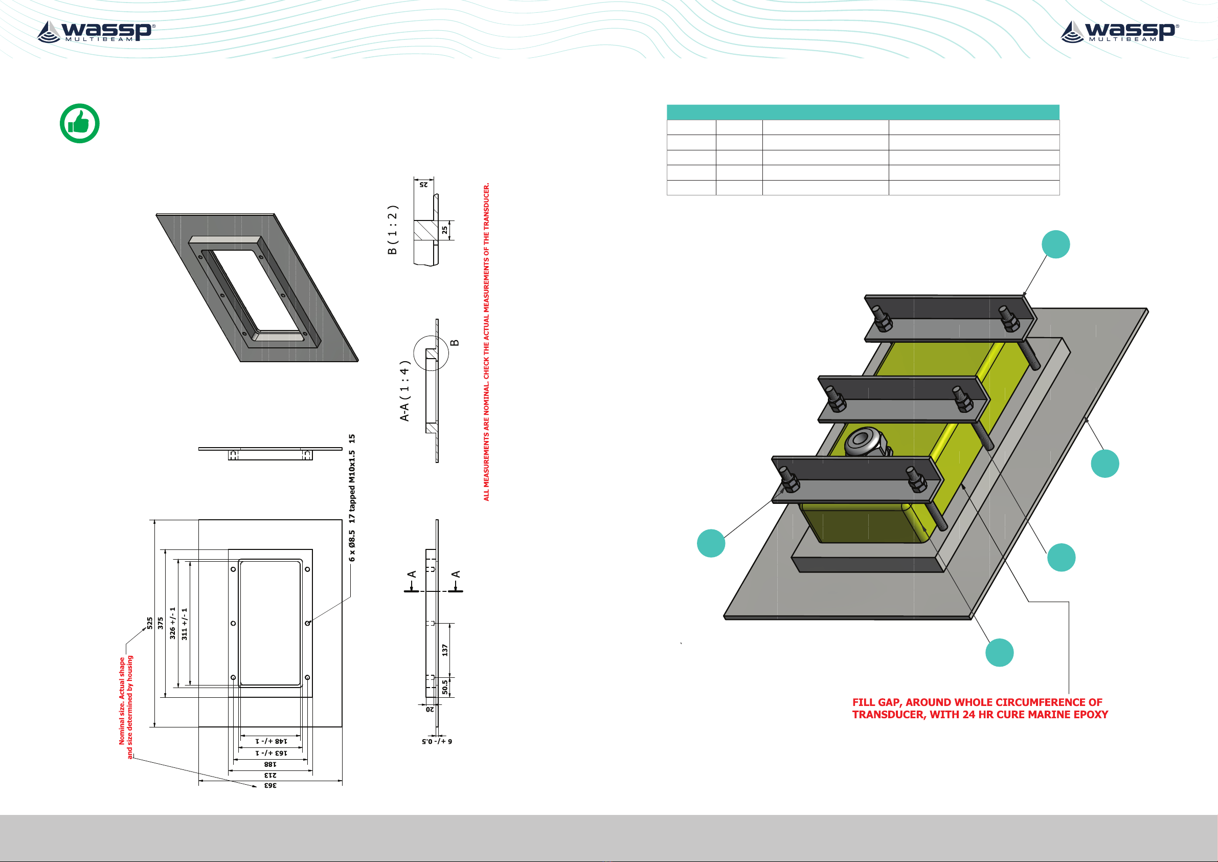
CAUTION: Please see "5 Mounting Assembly" on page 14. In particular
pay attention to the torque tension of the mounting nuts and the
requirement to fill any gaps that exist between the transducer body and the
retaining with epoxy.
A non-solvent based anti-fouling must be applied to the transducer face

Page 14 of 34 Page 15 of 34Doc: Transducer Installation
Version: 2.6 May 2021
Doc: Transducer Installation
Version: 2.6 May 2021
wassp.com wassp.com
TRANSDUCER INSTALLATION MANUALTRANSDUCER INSTALLATION MANUAL
5 MOUNTING ASSEMBLY
NOTE: For the following transducers, mounting parts are not included in
the package.
5.1. 160KHZ TRANSDUCER MOUNTING
xx
PARTS LIST
ITEM QTY PART DESCRIPTION
1 1 Transducer WSP-501-160
2 1 Mounting Plate Optional: Mild Steel
3 3 Angle Iron Clamp Optional: 40 x 40 x 5mm mild steel
4 6 Threaded end Optional: M10 x 1.5 120mm
5 12 M10 nut Optional
1
2
4
3
5

Page 16 of 34 Page 17 of 34Doc: Transducer Installation
Version: 2.6 May 2021
Doc: Transducer Installation
Version: 2.6 May 2021
wassp.com wassp.com
TRANSDUCER INSTALLATION MANUALTRANSDUCER INSTALLATION MANUAL
5.2. 80KHZ TRANSDUCER MOUNTING ASSEMBLY
All measurements are nominal. Check measurement of the actual transducer.
100
50.0
5.0
371
400
ø
12.5 THRU

Page 18 of 34 Page 19 of 34Doc: Transducer Installation
Version: 2.6 May 2021
Doc: Transducer Installation
Version: 2.6 May 2021
wassp.com wassp.com
TRANSDUCER INSTALLATION MANUALTRANSDUCER INSTALLATION MANUAL
Tighten the nuts indicated by "4" to a torque of 1.5-2Nm.
If any gaps exist between the transducer body "6" and the mounting frame "1" they
will need to be filled by a water proof 24hr cure epoxy.
All measurements are nominal. Check measurement of the actual transducer.
4
4
4
6
1
5.3. WIDEBAND FAIRING TRANSDUCER 90190KHZ MOUNTING
Part List (WSP-002-133 & WSP-002-134)
ITEM QTY PART DESCRIPTION
1 1 Fairing Block Optional
2 2 Threaded rod Optional: M12
3 2 Locking nut Optional: M12 Nyloc
4 6 Washer Optional: M12
5 6 Nut Optional: M12
Not included:
- Mounting tools
- Marine sealant
392
15.40
32.70
110
A A
524
7
166.50
207
184
202.50
281
SECTION A-A
REV.
DESCRIPTION
DATE
UPDATED BY
CHECKED BY
01
INITIAL RELEASE
29-01-2020
ALEXANDRA OETZEL
CRAIG SHANNON
GENERAL TOLERANCES UNLESS OTHERWISE SPECIFIED (MEDIUM)
≤3
>3-6
>6-30
>30-120
>120-400
>400-1000 >1000-2000
0.1 0.1 0.2 0.3 0.5 0.8 1.2 1.0
GENERAL TOLERANCES UNLESS OTHERWISE SPECIFIED (FINE)
≤3
>3-6
>6-30
>30-120
>120-400
>400-1000 >1000-2000
0.05 0.05
0.1
0.15
0.2 0.3 0.5 0.5
GENERAL TOLERANCES UNLESS OTHERWISE SPECIFIED (COARSE)
≤3
>3-6
>6-30
>30-120
>120-400
>400-1000 >1000-2000
0.2 0.3 0.5 0.8 1.2 2.0 3.0 2.0
F
E
4
2
17
5
38
6
B
C
D
A
1 OF 1
A3
CHECKED BY
DESCRIPTION
PART NUMBER
REVISION
DRAWN BY
PC
MATERIAL
Fairing
SHEET
SIZE
DATE
200600
29-01-2020
Alexandra Oetzel
Craig Shannon
B
C
D
E
F
A
18
67
5
4
3
2
GENERAL NOTES:
PART MUST BE CLEAN WITH NO SINKS, FLASH, SHARP EDGES OR BURRS.
1.
ALL DIMENSIONS ARE IN MILLIMETRES UNLESS OTHERWISE SPECIFIED.
2.
ALL DIMENSIONS AND TOLERANCES TO APPLY AFTER FINAL TEXTURING
3.
AND SURFACE FINISHING.
REFER TO CAD DATA FILE (200600.IGES/.STEP/.X_T) FOR MISSING
4.
DIMENSIONS.
UNLESS OTHERWISE STATED, ONLY USE RoHS COMPLIANT MATERIAL.
5.
This document contains confidential and proprietary information and rights that belongs to Electronic Navigation Ltd. Using, or permitting the use of, any of the information
contained herein, copying or imaging all or part of this document by any means, or permitting any such copying or imaging, or disclosing, or permitting the disclosure of,
any of its content to third parties is strictly forbidden without express written consent of Electronic Navigation Ltd. ©2019 Copyright Electronic Navigation Ltd.
CLIENT
Electronic
Navigation
FINISH
Black
COLOUR
Smooth
IF YOU OVERRIDE DIMESNIONS OR LINKS PLEASE MAKE A NOTE OF THIS OFF SHEET
STANDARD DRAWING NOTES (DELETE/ADD AS NEEDED):
PLASTIC PARTS:
SHEET METAL PARTS:
NOTES UNLESS OTHERWISE SPECIFIED:
NOMINAL DRAFT ANGLE: XX°
1.
NOMINAL WALL THICKNESS: XXmm
2.
ALLOWABLE FLASH: ±X.XXmm
3.
TRIM GATE: ±X.XXmm
4.
EJECTOR MARKS: ±X.XXmm
5.
CORNERS MOUDLED SHARP: RX.X MAX
6.
PART IDENTIFICATION:
7.
a. MOLD CAVITY NUMBER: 0.15mm RAISED
b. PART NUMBER: 0.15mm RAISED
c. PLASTIC GENERIC IDENTIFIER THIS AREA:
i. “PC/ABS”, FONT: ARIAL, 3mm HEIGHT, 0.15mm RAISED
ii. SPI ‘TRIANGULAR’ RESIN IDENTIFICATION CODE: 1… 7
d. DATE WHEEL FOR MONTH / YEAR
MACHINED PARTS:
NOTES UNLESS OTHERWISE SPECIFIED:
1.
NOTES UNLESS OTHERWISE SPECIFIED:
1.
NOTES UNLESS OTHERWISE SPECIFIED:
1.
ASSEMBLIES:

Page 20 of 34 Page 21 of 34Doc: Transducer Installation
Version: 2.6 May 2021
Doc: Transducer Installation
Version: 2.6 May 2021
wassp.com wassp.com
TRANSDUCER INSTALLATION MANUALTRANSDUCER INSTALLATION MANUAL
6 WASSP WIDEBAND FAIRING TRANSDUCER 90190KHZ
INSTALLATION
Follow the following guidelines:
»DO NOT use the WASSP Wideband Fairing Transducer 90-190kHz for boats
exceeding 40kn. Instead, use the WASSP 160kHz Transducer.
»A WASSP gland must be used to lead the WASSP transducer cable through the hull.
»Mount the front of the transducer facing forward. (the transducer can be mounted
back to front if necessary. Enable the setting swap array in the corrections page of
the WASSP web pages)
»The fairing can be cut up to a 30 degrees deadrise.
»The Locking nuts must not exceed 30N-m torque when tightening the nuts.
»Ensure the threaded rods are isolated from the hull when installing on an aluminium
hull to prevent electrolysis.
»A coer dam must be installed to ensure hull integrity is maintained in the event of
forces in excess of 40kn water pressure (such as a collision).
»Consider a coerdam to ensure the structure of the hull in case of unexpected
events like collision.
6.1. MEASURE AND PREPARATION
1. Measure the deadrise of the hull at the
transducer mounting location.
2. Cut the fairing using the measured deadrise
angle. The cutting guide on the fairing can be
used to guide the fairing over a bandsaw table.
3. Hold the fairing against the outside of the hull
to make sure there is no spacing between the
fairing and the hull. Gaps could result in bending
and cracking the fairing.
4. Hold the backing block against inside of the hull
to make sure there is no spacing between the
backing block and the hull.
30° max.
5
AFT VIEW
CUTTING GUIDE
NOTE:
AFTER THE FAIRING IS CUT, THE
SECTION WITH THE CUTTING GUIDE
BECOMES THE BACKING BLOCK
5. Mark the locations for the 2 threaded rods while holding the fairing or the backing
block.
6. Mark the cavity for cable gland area.
7. In the cavity for cable gland area mark the position for the gland. Make sure to
allow at least 4cm distance between the centre of the WASSP gland and the
outside of the gland cavity area.
Consider the space available in the cavity for cable gland area of the backing block when
using the WASSP Wideband Fairing Transducer 90-190kHz with fairing. Additional space
can be created by creating a gland relief cut-out in the backing block for additional space
to fit the gland or a relief for a suit bulk heads.
LOCATION OF CABLE GLAND
CAVITY FOR CABLE GLAND
CUTTING GUIDE
BOTTOM VIEW
BOW
C
C
AFT VIEW
TRANSDUCER
FAIRING
HULL
BACKING BLOCK
CABLE GLAND
CABLE
GLAND RELIEF
CUTTING LINE HIDDEN (BOTH, L AND K)

Page 22 of 34 Page 23 of 34Doc: Transducer Installation
Version: 2.6 May 2021
Doc: Transducer Installation
Version: 2.6 May 2021
wassp.com wassp.com
TRANSDUCER INSTALLATION MANUALTRANSDUCER INSTALLATION MANUAL
6.2. MOUNTING THE FAIRING
Drilling holes and final check before installation:
1. Hold the fairing against the hull and check the following
- The location of the threaded rod hole marks is correct (marked in step 5 of
“Measure and Preparation”)
- The location of the gland hole is at least 5cm away from the edge of the gland
cavity area.
- The distance between the two threaded rod holes is 392m.
2. Drill the holes for the threaded rods.
3. Place a nut 82mm above the transducer end of
the threaded rod and add a washer at the fairing
end. 82mm of thread is required to hold the
transducer (see 6.4)
4. Hold the fairing against the hull and push the long
end of the threaded rods up through the fairing
and hull all the way to the washer and nut.
5. Place the backing block over the gland.
6. Place a washer and two nuts on the threaded rods
inside the boat to secure the backing block.
7. Take the fairing and backing block o.
Mount the WASSP gland step 1 till 6 from chapter 7.2
6.3. FAIRING INSTALLATION
1. Apply a thick layer of marine sealant to:
a. The surface of the fairing that will be in contact with the hull.
b. The surface of the backing block that will be in contact with the hull.
c. The threaded rods
2. Again, place a washer and nut back above 82mm on the threaded rods.
3. Hold the fairing against the hull and push long end of the threaded rods through the
fairing and hull
4. Place the backing block over the gland.
5. Place a washer and two nuts on the threaded rods inside the boat to secure the
backing block not exceeding 30N-m. (make sure the length of the threaded rod under
the fairing is 82mm to the nut).
A A
A
THREADED ROD (2)
BACKING BLOCK
HULL
FAIRING
CABLE GLAND
BOW
MARINE SEALANT ON
WASHERS (2), BACKING
BLOCK, RODS (2)
MARINE SEALANT
ON FAIRING,
RECESS

Page 24 of 34 Page 25 of 34Doc: Transducer Installation
Version: 2.6 May 2021
Doc: Transducer Installation
Version: 2.6 May 2021
wassp.com wassp.com
TRANSDUCER INSTALLATION MANUALTRANSDUCER INSTALLATION MANUAL
6.4. TRANSDUCER INSTALLATION
1. Apply a thick layer of marine sealant to the TOP of the transducer that will contact the
fairing.
2. Guide the transducer cable trough the WASSP gland. Before guiding the transducer
into place, apply marine sealant between the gland pipe and the transducer cable and
push the sealant into the gap.
3. Guide the transducer in its position against the fairing. Make sure the side of the
Wideband Fairing Transducer 90-190kHz cable is forward.
4. Apply a washer and nylon locking nut to bolt threaded rods not exceeding 30N-
m. Make sure that the threaded rod protrudes at least 3mm from the nut but does
protrude the transducer face. This is so that it will not cause aeration when sealed o.
5. Fill the bolt holes on the face of the transducer ensuring that they are sealed and
flush, consider the product(s) used as it will need to be removed for the transducer to
be removed.
6. Remove any excess marine sealant when marine sealant has dried up.
7. Apply a non solvent based anti-fouling that covers the transducer face, housing and
fairing.
Finish locking the WASSP gland from step 8 onwards in chapter 7.2
7 CABLE INSTALLATION
7.1. GLAND ASSEMBLY
"Figure 8. Alloy / Plastic Gland Assembly Outline and Dimensions" shows the physical
dimensions of the WASSP Ltd. supplied alloy / plastic gland assembly. The steel gland is
dierent to below.
Figure 8. Alloy / Plastic Gland Assembly Outline and Dimensions
Figure 9. Steel Gland Assembly Outline and Dimensions
7.2. MOUNTING THE CABLE GLAND
Depending on the boat the transducer to be installed and the type of gland being used, there
are various ways of mounting the cable gland to the hull. Adapt the following procedures to
suit your installation while taking the following into consideration:

Page 26 of 34 Page 27 of 34Doc: Transducer Installation
Version: 2.6 May 2021
Doc: Transducer Installation
Version: 2.6 May 2021
wassp.com wassp.com
TRANSDUCER INSTALLATION MANUALTRANSDUCER INSTALLATION MANUAL
»Use personal protection gear such as safety goggles and dust mask during
installation. Make sure the work area is well ventilated when using sealant and
cleaning solvent.
»Always use a good quality marine sealant to seal across the areas that can leak (See
"Figure 10. Mounting the Gland Assembly" on page 26). Before applying marine
sealant to the parts, make sure they are free from oil and water. Use general cleaning
solvent to remove oil or grease if needed.
»Make sure all the gland parts are installed and are installed at the correct order.
»When installing the gland packing ring, apply soapy water to the cable to assist
installation if necessary. Clean o all the soapy water and dry all the parts before
applying sealant.
Red colour =marine sealant
Figure 10. Mounting the Gland Assembly
1Apply marine sealant to the upper side of the gland pipe flange.
2Place the bottom gasket over the gland pipe. Apply marine sealant to the
gasket.
3Push the gland pipe into the hole in the vessel hull.
4Apply marine sealant to both sides of the top gasket. Place the top gasket
over the gland pipe.
5Place the hull plate over the gland pipe and onto the top gasket.
6
Apply marine sealant around the gap between the hull plate and the gland
pipe. Screw the lock plate onto the gland pipe using a spanner. Tighten the
lock plate until a good joint is achieved. Clean excess marine sealant. Lock
the lock plate lock screw using an allen key.
7Feed the transducer cable through the gland.
8Apply marine sealant between the gland pipe and the transducer cable. Push
the sealant to the gap.
9Install the gland packing ring.
10 Install the steel washer.
11 Install the gland lock nut.
12 Install the gland nut.
13
Tighten the gland nut by hand until the components are aligned. Use a
spanner to further tighten the nut with light arm force for around 1 to 1.5 turn
until an increase in resistance is felt. After that, further tighten the nut by 2
turns or tighten to 30Nm. Tighten the lock nut against the gland nut. Double
check the tightening by measuring the length from the nut bottom edge to
the ending edge of the nut thread on the gland body (length A) for aluminium
and acetal glands (Figure 10). With steel glands, check the length from the
nut bottom edge to the flat surface on the gland base (length B in Figure 11).
Length A needs to be less than 20mm. Length B needs to be less than 14mm.
Figure 11. Gland nut travel measurement point for
acetal and aluminium glands
Figure 12. Gland nut travel measurement point for
steel glands
14
After the gland nut and lock nut are tightened and the marine sealant is
cured, place the boat in water and carefully check the gland for leaks. If leak
is observed, tighten the gland nut further by 0.25-0.5 turn. If leak continues
or leak is found at the gland base, uninstall the gland, check the conditions of
all the parts and repeat the installation procedures immediately. Recheck the
gland for leak 6 hours after the boat is in water.

Page 28 of 34 Page 29 of 34Doc: Transducer Installation
Version: 2.6 May 2021
Doc: Transducer Installation
Version: 2.6 May 2021
wassp.com wassp.com
TRANSDUCER INSTALLATION MANUALTRANSDUCER INSTALLATION MANUAL
7.3. TRANSDUCER CABLE
The transducer cable consists of seven CAT-5 cables and one
screened pair for the transmit connection.
To fit the RJ-45 connectors and cable through the gland, no
special preparation is required.
The WASSP transceiver cable end has the RJ-45 connectors
fitted with “staggered” cable lengths. This allows each RJ-45
connector and its associated cable to be fed through the gland
fitting easily.
Commencing with the black RJ-45 cable and black transmit
cable, feed each cable in turn through the gland, finishing o
with the grey RJ-45 connector and cable.
Complete fitting and tightening the gland as shown in "Figure
10. Mounting the Gland Assembly" on page 26.
NOTE: Colour code for transmit cable
conductors: White, Black and Green.
CAUTION: DO NOT STRAIN THE TRANSDUCER
CABLE!
Forcing the cable to bend, twist, or stretch
beyond its means will damage the transducer
and impair performance.
Once the transducer has been installed, ensure
that the transducer cable is not under tension.
Use cable ties (or similar) to secure the cable as
necessary.
Figure 13. Gland Assembly
- Cable Connectors
7.3.1. Replacing / Repairing an RJ-45 Connector
If one or more of the RJ-45 connectors gets damaged during the installation process,
the connector can be easily replaced. Wiring details and colour codes used are shown
below.
Screen / drain wire
Blue and Blue White
Brown and Brown / White
Green and Green / White
Orange and Orange / White
The CAT5E cables used in the transducer
cable follow standard CAT5 colour codes
but the RJ-45 plug wiring is specific to the
WASSP transceiver and does NOT conform
to T568A or B:
RJ-45 Plug Pin
Number CAT 5 conductor colour
1 Orange
2 Orange / White
3 Green
4 Green / White
5 Blue
6 Blue / White
7 Brown
8 Brown / White
Case Screen / drain wire (solder)
Pin #8 Pin #1
The screen / drain wire should be soldered onto
the side of the RJ-45 connector. Scratch the side
of the connector with something sharp before
soldering to assist with the join.

Page 30 of 34 Page 31 of 34Doc: Transducer Installation
Version: 2.6 May 2021
Doc: Transducer Installation
Version: 2.6 May 2021
wassp.com wassp.com
TRANSDUCER INSTALLATION MANUALTRANSDUCER INSTALLATION MANUAL
8 CABLE CONNECTION TO DRX
Transducer Receive Channels should be discharged prior to connection to the DRX. This
should be done every time the DRX is connected to the transducer.
To discharge the Transducer:
1. Peel o the cover label on DRX front panel, remove the black blanking plastic on
the X/TX port.
2. Plug each of the 7 Transducer Receive Cables into X/TX socket in turn.
Once discharge has been performed on every cable connect each cable to the correct
receive port on the DRX. For further information on connection to the DRX see the DRX
Installation Manual
If this label shown in Figure 12 is not present
on delivery, then discharge is not available
on this DRX. In this event you may have
been supplied with an external discharge
module.
If you plan to connect any transducer to a
DRX and your unit does not have a built-in
discharge port then we recommend you
request an external discharge module to
prevent damage to your DRX.
Figure 14. DRX with the Transducer Receive
Discharge cover label instruction
CAUTION: Failure to discharge the transducer prior to connection to the
DRX may result in irreparable damage to the DRX.
If you have an external discharge module follow the same procedure as above but use
the external discharge module rather than the X/TX socket to discharge the individual
Transducer Receive Channels each time you wish to connect the transducer to the DRX.
For the 80kHz Transducer, it is important that the receive channels are discharged prior
to connection to the DRX.
To discharge the transducer use the supplied
Ceramic Discharge Module (shipped with
WASSP 80kHz Transducers).
Figure 15. Ceramic Discharge Module
Connect each of the 7 Transducer Receive
Cables in turn to the RJ45 socket on the
Discharge Module. Connection will result in
the receive ceramics discharging through the
module.
This procedure should be carried out no more
that 10 minutes prior to connecting cables to
the DRX.
Figure 16. Discharging Transducer Channels

Page 32 of 34 Doc: Transducer Installation
Version: 2.6 May 2021
wassp.com
TRANSDUCER INSTALLATION MANUAL
9 TECHNICAL SPECIFICATION
The table below gives nominal mechanical and performance specifications for WASSP
Transducers.
160KHZ TRANSDUCER Wideband Fairing
Transducer 90-190kHz
80KHZ TRANSDUCER
Mechanical
Weight 12 (10m cable) 14.5 (10m cable) 29 (20m cable)
Height [mm] 94 85.5 130
Width [mm] 163 166.5 336
Length [mm] 326 524 527
Performance
Swath Width 120° 120° 120°
Beamwidth Fore Aft 3.2° 3.2° 3.2°
Beamwidth Port
Starboard
4.4° 4.4° 4.4°
TVR 159 dB 159 dB 159 dB
RVR -194 dB -194 dB -194 dB
Cable Gland Assembly
Static Pressure 6bar* 6bar* 6bar*
*Require installation as per instructions in manual
Table 1. Technical Specification
10 PRODUCT REGISTRATION, SUPPORT AND
RESOURCES
TECHNICAL SUPPORT
If you require maintenance and/or repair contact your local dealer. A list of WASSP
dealers and distributors is available at wassp.com.
DRX technical support is available directly through:
»Online: http://wassp.com/support/ and click on ‘Request Support’
LATEST RESOURCES
»For the latest version of manuals: http://wassp.com/manuals/
»For software updates and release notes: http://wassp.com/software-updates/
»For system drawings, mechanical drawings and declarations of conformity:
http://wassp.com/dealer-resource

This manual suits for next models
2
Table of contents
Popular Transducer manuals by other brands

MKS
MKS UniMag 971 Operation and installation manual

novotechnik
novotechnik LS1 Series manual

Camille Bauer
Camille Bauer SINEAX U 554 operating instructions

Minebea
Minebea TMHSAD-01 instruction manual

Absolute Measurement
Absolute Measurement CLT instruction manual

Thyracont
Thyracont VSR53PN operating instructions

FuehlerSysteme
FuehlerSysteme RTM1/E manual

Airmar
Airmar B66V Owner's guide & installation instructions

Airmar
Airmar R109LH Owner's guide and installation instructions

WIKA
WIKA F9204 operating instructions

S+S Regeltechnik
S+S Regeltechnik PREMASGARD 1140 Operating Instructions, Mounting & Installation

WIKA
WIKA Mensor CPT6030 operating instructions