WATANABE ELECTRIC INDUSTRY TW-3K User manual

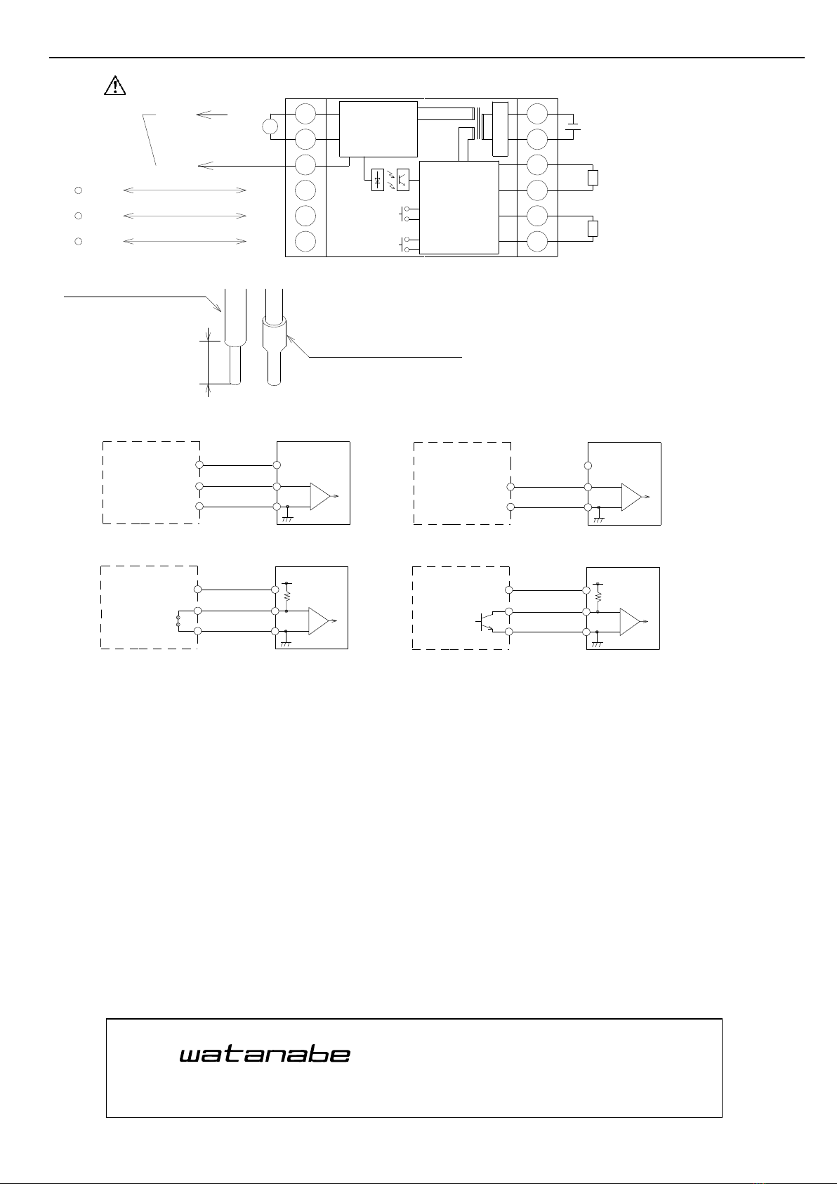
(1)If voltage or current exceeding the input allowable voltage or
current is applied to the input terminals, the transducer may be
damaged.
(2)Apply power within the applicable range of the transducer.
Otherwise fire, electric shock or transducer damage may result.
(3)The contents of this instruction manual are subject to change
without prior notice.
(4)This instruction manual is carefully prepared. However, if any
mistake or omission is found, contact your nearest Watanabe
Electric Industry sales agent or Watanabe Electric Industry
directly.
(5)Make this manual available easily anytime.
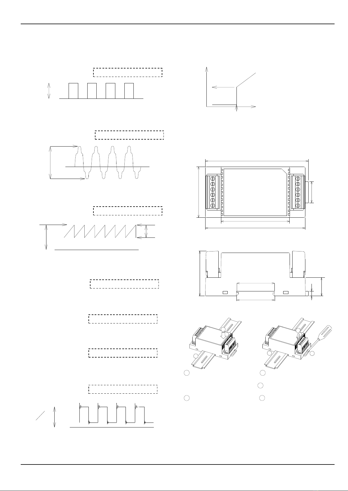
■Outline
The TW-3K electrically insulates and transducers pulse inputs
into DC voltage or current, then outputs them. The input and
output ranges can be changed by customers by way of the
communication setting. Using a microcomputer circuit, the TW-3K
transducers pulse inputs into standardized signals and outputs
them. The output level can be adjusted using a tactile switch
(within ±5 percent of full scale )on the front panel. The transducer
also incorporates a 12V/30mA power supply for sensors, which is
provided with short-circuit protection. The cut point setting
function can output 0 percent signals when the input level is lower
than a preset value.
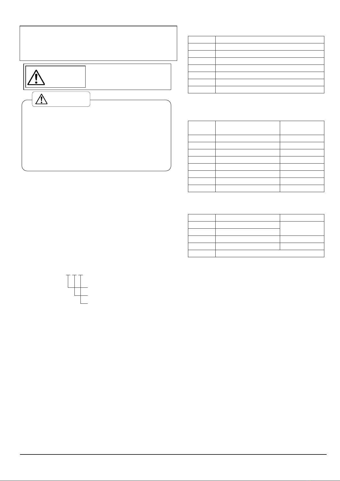
■Model and suffix codes to specify
Each code and the standard specifications are as follows.
First check whether or not your desired specifications are correct by
comparing them to the following specifications.
■General specifications
Accuracy
:Within ±0.20% F.S
Allowable fluctuation
range for power supply
load
:Within ±0.15%F.S
Temperature characteristic
:±0.02F.S/℃
Response time
:1.5secnds+one cycle of pulse input
(from 0 to 90%)
Power supply voltage
:24V DC±10%
Insulation resistance
:Between the input and output or
power supply, More than 100MΩ
Dielectric strength
:Between the input and output or
power supply, For 1 min. at 1500V
DC
Consuming current
:Within 110mA (sensor power
supply:30mA)
Operating ambient
temperature/humidity
:-5 to +50℃/Less than 90%RH
(No-condensing)
Storage
temperature/humidity
:-10 to +70℃/Less than 60%RH
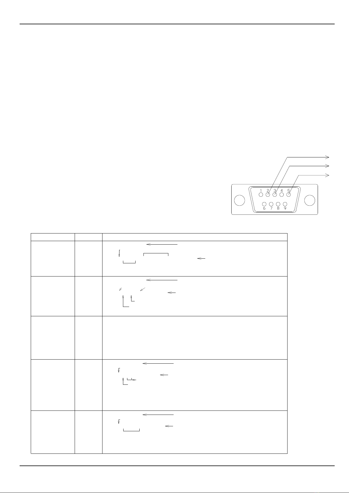
(No-condensing)
Zero adjustable range
:Within ±5%F.S
Span adjustable range
:Within ±5%F.S
Case material
:Black PBT 94-VO
Weight
:Less than 150g
■Input type codes
See page 2 for a detailed description of the inputs.
Code No.
Input type
A
TTL(5V)
B
Voltage pulse(0 crossing of the input voltage)
C
Voltage pulse (Not 0 crossing of the input voltage)
D
Open collector (detected voltage:5V DC/1mA)
E
Open collector (detected voltage:12V DC/1mA)
F
Contact switch (detected voltage:5V DC/1mA)
G
Contact switch (detected voltage:12V DC/1mA)
*When Code No.C is chosen, measuring range code are 5 to 7.
*When code No.F or G is chosen, measuring range code are 1 to 4.
And measuring range is 0 to 30Hz.
■Measuring range codes
Code No.
Measuring range
Minimum
span
1
0 to 0.1Hz
At least 0.01Hz
2
0 to 1Hz
At least 0.2Hz
3
0 to 10Hz
At least 2Hz
4
0 to 100Hz
At least 20Hz
5
0 to 1kHz
At least 100Hz
6
0 to 10kHz
At least 1kHz
7
0 to 100kHz
At least 10kHz
Y
Other than the above
See note below
Note: The minimum span for code Y is the same as that for the
code covering the desired measuring range.
■Output type codes and their specifications
Code No.
Output type
Load resistance
0
0 to 5V DC
At least 2kΩ
1
1 to 5V DC
2
0 to 10V DC
At least 4kΩ
A
4 to 20mA DC
Less than 550Ω
Y
Other than the above
*When the input frequency exceeds 100 percent of the full scale,
signals ranging from 105 to 110 percent of the full scale are
output.
For code No. Y limit of specifications
Voltage:0 to 10V in 1V increments
Current:0 to 20mA in 1mA increments
■Output calibration and button lock function
The output signals need to be calibrated using the tactile switch on
the front panel, which is normally prohibited when the button lock
function is in place. Cancel the button lock before calibrating the
output signals.
Canceling the button lock function:Press the SPAN/UP▲ and
ZERO/DOWN▼buttons and hold them for at least 3 seconds, then
release them.
Adjusting the output signals:A signal press of the tactile switch
changes the output by 0.01 percent of the full scale.
Press the switch for at least 300 msec. The output can be changed by
0.1 percent of the full scale by pressing and holding the switch for
over 3 seconds.
Note: When 30 seconds have elapsed without any buttons being
pressed after the button lock has been canceled, the buttons are
automatically locked again. Contact WATANABE to change this
time limit.
When the transducer is to be calibrated for securing prolonged
accuracy, use standard measuring instruments with 10-fold or
greater accuracy compared with the TW-3K.
PULSE/ANALOG TRANSDUCER
INSTRUCTION MANUAL
MODEL TW-3K
Precautions
Warning
This marking indicates that
the erroneous operation of
this transducer may result in de
ath or serious
injury.
T W - 3 K - □ □ □ - C
Input type
Output type
Measuring range
(1/4)
WATANABE ELECTRIC INDUSTRY CO., LTD.

■Input types and their details
The input type cannot be changed using the communication setting.
Be sure to specify it during the ordering procedures.
<Code No.:A>TTL
Measuring ranges:From 0 to 0.1Hz, to 0 to 100kHz
Detected level:5V DC(duty ratio:20 to 80%)
<Waveform example>
<Code No.:B>Voltage pulse(0 crossing of the input voltage)
Measuring ranges:From 0 to 0.1Hz, to 0 to 100kHz
Detected level:4V to 50Vp-p including DC offset components
(duty ratio:20 to 80%)
<Waveform example>
<Code No.:C>Voltage pulse(Not 0 crossing of the input voltage)
Measuring ranges:From 0 to 1000Hz, to 0 to 100kHz
Detected level:4V to 50Vp-p, including DC offset components
(duty ratio:20 to 80%)
<Waveform example>
<Code No.:D>Open collector for 5V detected voltage
Measuring ranges:From 0 to 0.01Hz, to 0 to 100kHz
Detected level:On at 700Ωmax. and off at 3kΩ min.
(duty ratio:20 to 80%)
<Code No.:E>Open collector for 12V detected voltage
Measuring ranges:From 0 to 0.01Hz, to 0 to 100kHz
Detected level:On at 700Ω max. and off at 2.4kΩ min.
(duty ratio:20 to 80%)
<Code No.:F>Contact switch for 5V detected voltage
Measuring ranges:From 0 to 0.01Hz, to 0 to 30Hz
Detected level:On at 700Ω max. and off at 3kΩ min.
(duty ratio:40 to 60%)
<Code No.:G>Contact switch for 12V detected voltage
Measuring ranges:From 0 to 0.01Hz, to 0 to 30Hz
Detected level:On at 700Ωmax. and off at 2.4kΩ min.
(duty ratio:40 to 60%)
<Waveform example>
■Cut point
The transducer outputs 0 percent signals when the input level is
lower than preset cut point. The cut point can be set to 0.0 to 99.9
percent in units of 0.1 percent.
■Sensor power supply
12V DC±1% and 30mA
Short-circuit protection provided: Outputs approximately 360mA
for short-circuits
■Dimensions
Front view
Side view
■Mounting/Dismounting
■Mounting ■Dismounting
A
Engage the left side of the
A
Push down the slider with a
screwdriver.
transducer with the rail.
B
Push up the right side of the
transducer.
B
Push the right side of the
C
Disengage the left side of the
transducer
transducer into the rail. from the rail.
*If the transducer is likely to be dislocated after its mounting, it is
recommended that a clamp be used.
(For example E/NS35N made by PHOENIX CONTACT)
0V
(50V max)
5V
Detection voltage: About 1.25V
Detection voltage: About 0.2V
50V max.
0V
Detection voltage: About 0.2V
Detection voltage: About 1.25V
0V
4Vp-p min.
50V max.
0V
12V
5V
Input signal (Hz)
Cut point value
Cut area
Output signal
9 4
4 8
6 4 . 5
3 5 . 4
3 5 . 2
4 . 5
1 7 . 4
4 2 . 5
2 0
Sl i d i ng f rom 9 6 t o 9 8
B
AA
C
B
INSTRUCTION MANUAL MODEL TW-3K (2/4)
WATANABE ELECTRIC INDUSTRY CO., LTD.

■Communication setting
The measuring range, output, adjustment range, and cut point can be changed using the communication setting as follows. Be sure to read
“Input type and their details,” “Measuring range codes,” “Output type codes and their specifications,” and “Cut point” before changing these
settings.
<Setting items><Communication specifications>
①Measuring range The TW-3K parameters can be set with communication software using an RS232C port of
②Output type and range a personal computer.
③Output type and adjustment(adjustable range)Recommended software: Hyper Terminal in Windows
Zero adjustment A communication cable must be provided by the user.
(using the tactile switch on the front panel) ①Electrical characteristics:EIA RS232C compliant ⑦Error detection:None
Span adjustment ②Communication method: Full duplex ⑧Stop bit:1 bit
(using the tactile switch on the front panel) ③Synchronization method: Asynchronous ⑨Transmission control protocol:
Adjustment of 25% level ④Transmission speed: 9600 bps Non-procedural
Adjustment of 50% level ⑤Start bit : 1 bit ⑩Character code: ASCII
Adjustment of 75% level ⑥Data length : 8 bits ⑪Required signals: TXD,RXD, and SG only
④Cut point ⑫Delimiter:CRLF
<Command conventions>
①Commands must be entered in capital letters.
②Entering a command name and the enter key returns the current data for the specified
command from the TW-3K.
③Entering a command name, the space key, then a setting value transmits the setting for
the specified command to the TW-3K.
④When the command has been successfully transmitted, the transducer returns “Yes”.
⑤When an erroneous command name is entered, the transducer replies with “No”.
⑥When the setting is not adequate including being outside the range, the transducer
returns “Error”.
<Command list and description>
Before changing the setting, connect the power supply, an input and output, and an RS232C port to the TW-3K by consulting the wiring diagram
on page 4. When the output type and range have been changed, be sure to adjust the 25%, 50%, and 75% levels as well.
Wiring arrangement for 9-pin D-sub connector
To TW-3K's TXD terminal
To TW-3K's SG terminal
To TW-3K's RXD terminal
space key
F I N □0 . 0 0 , 1 0 0 0 . 0 0 [Enter key]
F I N [Enter key]
F I N
Setting item Description
Returns the current input range.
Maximum input
Minimum input
The setting transmission formats are
Measuring range
Zero adjustment
(Span adjustment)
“minimum input, maximum input”.
*Enter the settings to two decimal
places in Hz.
Retures the current output range and type.
space key
O U T [Enter key]
O U T □1 , 5 , 0 [Enter key]
Minimum output
Maximum output
Output type
O U T
Output type and range
The setting transmission formats are
*Output type : 0:voltage (in 1V increments)
1:current (in 1mA increments)
ZSCP command : Changes zero adjustable range
SSCP command : Changes span adjustable range
Note that although the zero and span ranges can be increased and decreased, the TW-3K
does not actually output signals outside of 0 to 10V (from 0 to 20mA). The allowable
setting range is 5 to 99 percent of the full scale (enter the setting as integers).
S 2 5
space key
S 2 5 [Enter key]
S 2 5 □ + 1 0 [Enter key]
Adjustment of 25% level
Returns the current 25 percent level setting.
Sign
Setting
The setting transmission format is “sign (±) setting”.
Enter the setting as integers.
The adjustment setting is possible within ±100mV (μA) range in 1mV ( μA) increments.
Ajdust signals as necessary by inputting 25 percent signals of the full scale
(50 percent and 75 percent) and measuring the outputs.
( S 5 0 )
( S 7 5 )
(Adjustment of 50% level)
(Adjustment of 75% level)
space key
F C P [Enter key]
F C P □ 1 0 . 0 0 [Enter key]
F C P
Cut point
Returns the current cut point setting.
Setting
The setting transmission format is “setting”.
Enter the setting to two decimal places in percentage.
the full scale.
full scale.
Allow for a cutting error of ±0.05 percent of the
Command name
“minimum output, maximum output, output type”.
*Enter the settings as integers.
See “Output calibration and button lock function”on page 1. The normal adjustable
range is ±5 percent of the full scale. To change the range, use the following commands:
The allowable setting range is 0 to 99.99 percent of
INSTRUCTION MANUAL MODEL TW-3K (3/4)
WATANABE ELECTRIC INDUSTRY CO., LTD.

■Block wiring diagram
Exercise caution to ensure the correct polarity.
■Recommended treatment of wires connected to connector type terminal board
■Wiring example
■Caution
・Store the converter at a location having a storage temperature of -10 to +70℃and a humidity of less than 60% RH.
・Use the converter at a location where there are no chemicals or gases harmful to its electrical parts or there is no dust.
・Do not apply any vibration or impact to the converter.
・In order to lessen the effect of noise, etc. do not bundle the input/output wires with the power supply wires, nor put these wires in the same
duct.
■Warranty
This transducer is warranted for a period of one year from date of delivery. Any defect which occurs in this period and is undoubtedly
caused by Watanabe Electric Industry faults will be remedied free of charge.
This warranty does not apply to the transducer showing abuse or damage which has been altered or repaired by others except as authorized by
Watanabe Electric Industry.
■After-sale service
This transducer is delivered after being manufactured, tested and inspected under strict quality control.
However, if any problem does occur, contact your nearest Watanabe Electric Industry sales agent or Watanabe Electric Industry directly giving
as much information on problem as possible.
■Accessories
Terminal Cover 2pc.
Detachable 6-P connector 2pc.
7
8
9
10
11
126
5
4
3
2
1S P A N
-
+
Z E R O
-
+
-
+
-
+
G N D
G N D
R X D
T X D
S G
T X D
R X D
Input
12V DC
Communication equipment
Constant-voltage
circuit
Input circuit
Output circuit
power supply
Sensor
Power supply
circuit
DC power supply
Voltage output
Current output
signal
S i n g l e w i r e s i z e : 1 . 4 φ
Recommended bar terminal
M a d e b y p h o e n i x ( A I 1 . 5 - 8 B K )
Twisted wire size:1.5mm2
8
Stripped covering length
INSTRUCTION MANUAL MODEL TW-3K UW-33838i (4/4)
4
5
6
P WR
GND
I NPUT +
PO WER
T W-3K
4
5
6
P WR
GND
I NPUT +
T W-3K
NC
12V DC/30mA
Voltage pulse input Input pulse input
4
5
6
P WR
GND
I NPUT +
PO WE R
T W-3 K
4
5
6
P WR
GND
I NPUT +
POWER
T W-3 K
Open collector
Open
collector
12V DC/30mA
12V DC/30mA
Contact switch
Limit switc h
Lead switch
5V or 12V
R1
5V or 12V
R1
R1
R1
at 5V:4.7kΩ
at 12V:12kΩ
at 5V:4.7kΩ
at 12V:12kΩ
WATANABE ELECTRIC INDUSTRY CO., LTD.
6-16-19, Jingumae, Shibuya-ku, Tokyo 150-0001, Japan
Phone: (81)3-3400-6140
Homepage http://en.watanabe-electric.co.jp/
ASAHI KEIKI DIVISION
WATANABE ELECTRIC INDUSTRY CO., LTD.
6-16-19, Jingumae, Shibuya-ku, Tokyo 150-0001, Japan
Phone: (81)3-3400-6141
Homepage http://www.watanabe-electric.co.jp/en/
Other WATANABE ELECTRIC INDUSTRY Transducer manuals