Waterbird ITSC1000 User manual

Copyright © 2017 Waterbird Systems GmbH
www.waterbird.at
Control Unit
User Manual
Version 1.0

Copyright © 2017 Waterbird Systems GmbH
www.waterbird.at
Table of Contents
1. Control Unit ITSC1000 ................................................................................................................. - 1 -
1.1 Technical Data ..................................................................................................................... - 1 -
1.2 Interface Definition ............................................................................................................. - 2 -
1.3 Mounting and Dismounting on Slider ................................................................................. - 4 -
Mounting Bracket........................................................................................................................ - 4 -
Mounting of Control Unit ............................................................................................................ - 4 -
Dismounting of Control Unit ....................................................................................................... - 4 -
1.4 Handling and Safety Instructions ........................................................................................ - 5 -
1.5 Troubleshooting .................................................................................................................. - 6 -
1.6 Regulatory Hints .................................................................................................................. - 7 -
2. Mobile App .................................................................................................................................. - 9 -
2.1 Operating Systems............................................................................................................... - 9 -
Android........................................................................................................................................ - 9 -
iOS................................................................................................................................................ - 9 -
2.2 Connecting to Control Unit.................................................................................................. - 9 -
2.3 System Initialization .......................................................................................................... - 10 -
2-Point-Initialization .................................................................................................................. - 10 -
1-Point-Initialization .................................................................................................................. - 10 -
2.4 System Control .................................................................................................................. - 11 -
Speed and Acceleration Control................................................................................................ - 11 -
Positioning................................................................................................................................. - 11 -
Emergency Stop......................................................................................................................... - 11 -
2.5 Camera Settings................................................................................................................. - 12 -
Shutter....................................................................................................................................... - 12 -
Focus.......................................................................................................................................... - 12 -
External Light............................................................................................................................. - 12 -
2.6 Timelapse .......................................................................................................................... - 13 -
Record Time............................................................................................................................... - 13 -
Movie Length............................................................................................................................. - 13 -
Interval ...................................................................................................................................... - 13 -
Pictures...................................................................................................................................... - 13 -
2.7 Features............................................................................................................................. - 14 -

Copyright © 2017 Waterbird Systems GmbH
www.waterbird.at
Ping-Pong Mode ........................................................................................................................ - 14 -
Step-By-Step Mode.................................................................................................................... - 14 -
2.8 Settings.............................................................................................................................. - 15 -
Initialization............................................................................................................................... - 15 -
Timelapse .................................................................................................................................. - 15 -
Controller Settings..................................................................................................................... - 15 -
2.9 Control Unit Firmware Update.......................................................................................... - 16 -

Multi Slider –User Manual
Copyright © 2017 Waterbird Systems GmbH
www.waterbird.at - 1 -
1. Control Unit ITSC1000
The ITSC1000 Control Unit is a controller for timelapse and digital motion control for video
and photo equipment. It allows to control up to 3 industrial class stepper motors and the
triggering of shutter and focus of a connected camera. Most models of popular cameras are
supported. Auxiliary input and output port for light control and motor control via an analog
voltage is also available.
For controlling the outputs the Control Unit has a built in Bluetooth® Smart 4.2 BLE compliant
module that allows the connection to a BT LE (Low Energy or 4.0 or higher) capable
Smartphone or Tablet. Applications for controlling the Unit are available for Android™ and iOS
powered devices on App Stores.
1.1 Technical Data
Operating Parameters
Temperature Range
20°C to +50°C (-4°F to 122°F)
Maximum Relative Humidity
90%, noncondensing
Ports & Connection
Supply Connector
5.5/2.1mm or 5.5/2.5mm (Outer/Inner diameter)
DC barrel - center positive
Supply Voltage
9 –16 Vdc stabilized voltage
Supply Current
Source shall be capable of providing minimum 2A
Motor Output
3 x Molex 22-05-3041
(fitting to Motor Connector Molex 22-01-3047)
Motor Type
Bipolar 4-wire stepper Motor
maximum 12V and 1,4A rated recommended
with a minimum isolation voltage of 24V
Camera Trigger Port
2,5mm (3/32”) Stereo Klinke / TRS
Sleeve: GND, Ring: Focus, Tip: Shutter
Internal pull-up 3,3V , Maximal Voltage: 5Vdc
Auxiliary Port
3,5mm (1/8”) Stereo Klinke / TRS
Sleeve: GND, Ring: Aux 2 In/Out, Tip: Aux 1 In/Out
Internal pull-up 3,3V , Maximal Voltage: 5Vdc
USB Port
USB Micro B
Used for Firmware Updates and future use
Max Voltage 5Vdc, no supply of motors via USB

Multi Slider –User Manual
Copyright © 2017 Waterbird Systems GmbH
www.waterbird.at - 2 -
1.2 Interface Definition
A, B, C) Motor Connectors
These are the connectors for connecting the bipolar stepping motors.
The Motor of the Slider carriage needs to be connected at Port A.
Motor Connector
Connected Motor
A
Motor of the Slider carriage
B
Not activated, for future use (e.g. Pan/Tilt, Up/Down or rotating)
C
Not activated, for future use (e.g. Pan/Tilt, Up/Down or rotating)
1) Supply DC Connector
The Supply DC Connector is the power source for Motor and Logic part. A stabilized DC voltage
between 9 –16 Vdc must be used. Typically 12V or 14V Battery packs are recommended.
2) Camera Trigger Connector
Control Unit can control a camera through the wired remote shutter port with 2.5mm Klinke
(3/32” Male TRS) connector. Standard Cables are available for most camera models on the
market.
Control Unit can control a camera through the wired remote shutter port with 2.5mm Klinke
(3/32” Male TRS) connector. Standard Cables are available for most camera models on the
market.
The Camera Trigger Connector provides control over the focus and shutter trigger only, it is
not possible to control ISO, aperture, or other settings of the camera over this port. If you set
your camera to bulb mode the control unit can control the shutter speed (if your camera
supports this mode).
3) LED Indicator
The blue LED Indicator shows the current status of the Control Unit. If no light is visible the
Control Unit is unpowered or in Bootloader Mode.

Multi Slider –User Manual
Copyright © 2017 Waterbird Systems GmbH
www.waterbird.at - 3 -
If the blue LED Indicator is flashing the Control Unit is waiting for a connection to a Control
device (e.g. Smartphone or Tablet).
If the blue LED Indicator is constantly on, the Control Unit is connected and ready to be used.
4) USB Connector
The USB connector can be used to control the Control Unit via a PC (Software planned to be
released in the future) and for firmware updates. Powering the Control Unit via USB is only
possible for firmware updates, no Motor control is possible if no power is available on the
Supply DC Connector.
5) Auxiliary Connector
This Port can be used to connect accessories like a manual knob or external controls e.g. to
control a light that is switching on and off before and after the picture taken for long duration
time-lapse.
6) Reset + Motor Off Button
This button can be pressed to reset the internal processor of the Control Unit. This causes also
a sudden stop of all connected Motors. You can use it if the System does not react as desired
to prevent from damaging equipment. Please take care that the Motors will not be powered
after pressing. And in case of vertical usage and high load the carriage could be pulled down
by gravity. After pressing the button the initialization of the slider needs to be repeated via
the App.

Multi Slider –User Manual
Copyright © 2017 Waterbird Systems GmbH
www.waterbird.at - 4 -
1.3 Mounting and Dismounting on Slider
Mounting Bracket
Together with the Control Unit comes a specialy designed mounting bracket to be mounted
on the carriage of the Slider System.
If you have bought the Control Unit as standalone device you first need to fix the mounting
bracket on your slider system with two countersunk screws.
If you have bought the set with Multi Slider the mounting plate is already fixed on the slider
carriage.
Mounting of Control Unit
To mount the Control Unit on the Mounting Bracket, first push the Control Unit on the
mounting bracket so it is aligned with the hooks, then push the Control Unit to the right side
as shown in picture till the snap-fit is in place.
Dismounting of Control Unit
To dismount the Control Unit from the Mounting Bracket, first push down the snap-fit with a
finger and move the Control Unit to the left while still holding down the snap-fit.

Multi Slider –User Manual
Copyright © 2017 Waterbird Systems GmbH
www.waterbird.at - 5 -
1.4 Handling and Safety Instructions
The Control Unit is designed to be mounted with the included mounting bracket. Do not use
another method of fixing the Control Unit to the Slider.
Do not use the Control Unit in wet or humid environment like rain, snow, spray or waterfalls
without extra protection against humidity intrusion in the electronic.
Do not install this Unit near a heater, inflammable material or oily or dusty location or in a
location continuously exposed to direct sunlight or in a location where gas may leak.
Do not cover the Control Unit with Metal Objects to ensure proper operation of the wireless
communication.
Do not attempt to repair, disassemble, or modify the Unit by yourself. There are no serviceable
parts inside and opening the Unit will void the warranty.
Remove all foreign substances such as dust or water from the power plug terminals using a
dry cloth on a regular basis. - Unplug all connectors and clean it with a dry cloth without
alcohol or other solvents.
Do not pull or excessively bend the cables. Do not twist or tie the cables. Do not hook the
cables over a metal object or place a heavy object on the cables. Do not pull the cables, when
unplugging unplug the connector by holding the plug. Do not put force on the cables in any
direction when connected to the Control Unit, this can damage the Control Unit and
connectors.
Before switching on the power to the Control Unit ensure that the Motors can spin feely and
no harm to humans, animals or objects is possible in case the connected motors start moving.
Do not use the Control Unit if it is damaged, the isolation on the cables is damaged or it shows
any abnormality like excessive heat dissipation that damaged the plastic housing.
It is normal that the Control Unit gets warm during operation. To avoid overheating do not
cover the Control Unit with thermally insulating material and allow free airflow.

Multi Slider –User Manual
Copyright © 2017 Waterbird Systems GmbH
www.waterbird.at - 6 -
1.5 Troubleshooting
Camera does not trigger/focus when function in app is used.
Please check the trigger cable if properly plugged into the control unit’s CAM socket
and to the camera.
Check if the Camera is switch on.
If focusing is not working check if the camera/lens is set to manual focus.
Some cameras require settings in the menu to allow external trigger cable to be used,
please check with the manual of your camera.
Motor does not start when function in app is used.
Please check if the motor cable is properly plugged into the control unit’s Motor socket
and the right socket is used (Socket A for Slider).
Check if the power supply is connected. If only USB is connected the Control Unit may
connect to the App, but the Motors will not work.
Check if supply voltage is in range 9-16 Vdc (The battery may be empty.)
Check if any error information is shown in the App.

Multi Slider –User Manual
Copyright © 2017 Waterbird Systems GmbH
www.waterbird.at - 7 -
1.6 Regulatory Hints
INSTRUCTION ABOUT THE WEEE MARK
Correct Disposal of This Product (Waste Electrical & Electronic Equipment)
(Applicable in countries with separate collection systems) This marking on the
product, accessories or literature indicates that the product and its electronic
accessories (cables, adapters,..) should not be disposed of with other household
waste at the end of their working life. To prevent possible harm to the environment or human
health from uncontrolled waste disposal, please separate these items from other types of
waste and recycle them responsibly to promote the sustainable reuse of material resources.
Household users should contact either the retailer where they purchased this product, or their
local government office, for details of where and how they can take these items for
environmentally safe recycling. Business users should contact their supplier and check the
terms and conditions of the purchase contract. This product and its electronic accessories
should not be mixed with other commercial wastes for disposal.
USA:

Multi Slider –User Manual
Copyright © 2017 Waterbird Systems GmbH
www.waterbird.at - 8 -
Canada:
China:
Multi Slider –User Manual
Copyright © 2017 Waterbird Systems GmbH
www.waterbird.at - 9 -
2. Mobile App
The mobile app Multi Slider is used as wireless remote control for the Multi
Slider Control Unit.
2.1 Operating Systems
The Mobile App for controlling the motorized Multi Slider is available for Android and iOS
Operating Systems.
Android
Min. Android Version: 5.0
Google Play Store: https://play.google.com/store/apps/details?id=at.waterbird.multislider
iOS
Min. iOS Version: 10.3
Apple App Store: https://itunes.apple.com/app/multi-slider/id1273882924
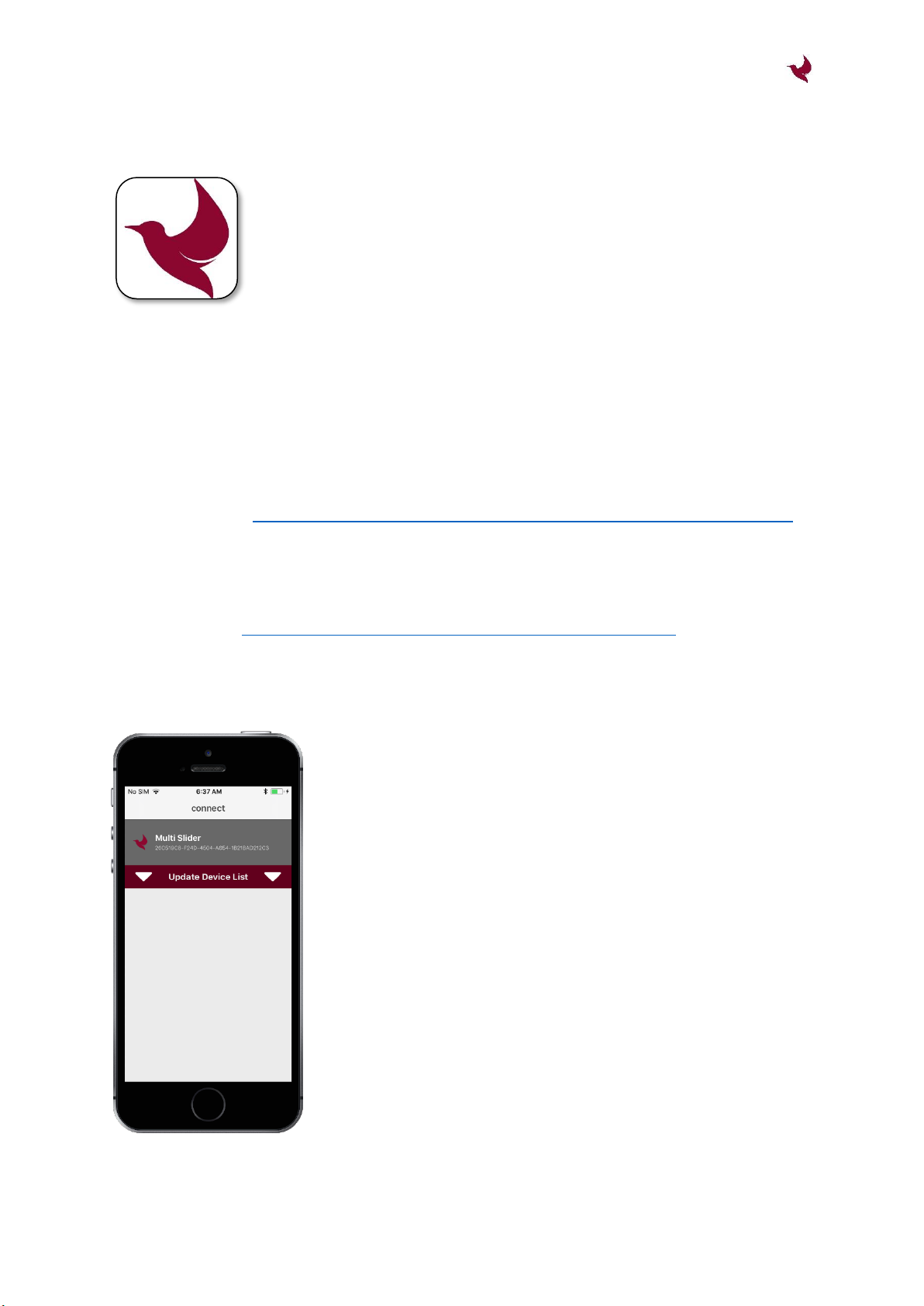
2.2 Connecting to Control Unit
The wireless connection to the Control Unit is established via
Bluetooth Low Energy (4.0).
Make sure the Control Unit is powered with 12V on the supply
connector before you start the Multi Slider App. At initial App
start you could be prompted to give necessary permission (e.g. to
enable Bluetooth).
During startup, the App scans for the Control Unit. If successful,
the Multi Slider is presented on the screen. Connection is
performed by touching the Multi Slider entry.
If the Multi Slider Control Unit was not found immediately, assure
the Control Unit is powered and its Blue LED flashes. Then restart
the scan by pulling down the “Update Device List” bar.
Additionally you can try to restart the mobile phone and/or reset
the Control Unit.

Multi Slider –User Manual
Copyright © 2017 Waterbird Systems GmbH
www.waterbird.at - 10 -
2.3 System Initialization
After powering or resetting the Control Unit the system is not
initialized. That means the software does not know the position
of the slider.
Therefore the endpoints (HOME and END position) needs to be
initialized in order to gain full functionality.
Initialization can be performed by 2-Point (default) or 1-Point
initialization. (cf. 2.8 –Initialization Mode)
With the initialization of the Multi Slider, the possible movement
area of the slide is bordered by the endpoints. This position area
is used for all automated features like Timelapse and Ping-Pong.
Furthermore, once initialization succeeded, it is not possible to
move the slide outside those defined endpoints.
Initialization can be cleared by hitting the blue “RESET” button.
2-Point-Initialization
For 2-Point-Initialization the END Position needs to be initialized first. Therefore, use the
buttons “<<<” and “>>>” to move the slide to your intended END position and hit the blue
“END” button.
The label of the blue button changes from “END” to “HOME”. So move the slide to your
intended HOME position. After hitting the blue “HOME” button the system is initialized.
1-Point-Initialization
If Initialization mode is set to 1-Piont-Initialization (cf. 2.8), then only the HOME position needs
to be initialized.
The END position is defined be the position area length stored on the Control Unit. Position
and length can be changed by performing a 2-Point-Initialization and saving the controller
settings afterwards. (cf. 2.8 –Controller Settings)

Multi Slider –User Manual
Copyright © 2017 Waterbird Systems GmbH
www.waterbird.at - 11 -
2.4 System Control
Once the system is initialized, speed and acceleration can be configured as needed and the
slider can be accurately positioned within the initialized endpoints.
Speed and Acceleration Control
For speed and acceleration adjustment there is a slider for rough
configuration, and for high accurate adjustment “+/-” - buttons
can be used.
The acceleration value is also used for deceleration when moving
to a target position.
Speed and acceleration values can also be changed during motor
movement and those settings are even valid for features like Ping-
Pong and Step-By-Step mode.
Positioning
The “RESET” button clears the position initialization and new
endpoints have to be configured.
The “STOP” button immediately stops the motor with a fast deceleration ramp.
With “HOME” and “END”-buttons the slider can be sent to the initialized endpoints.
The position slider offers a live view of the current slider position. Additionally it can be used
to send the motor to a dedicated position within the initialized endpoints.
With the touch-and-hold buttons “<<<” and “>>>” the motor moves into the dedicated
direction as long as the button is pressed.
Emergency Stop
For emergency stop use the white reset button on the Control Unit (cf. 1.2-6). This can also be
used when mobile App is not connected to the Control Unit.
Keep in mind that emergency stop releases power from the motor, therefore in vertical mode
motor is not actively held in position. This means that high loads can move downwards, forced
by gravity.

Multi Slider –User Manual
Copyright © 2017 Waterbird Systems GmbH
www.waterbird.at - 12 -
2.5 Camera Settings
Shutter
In the Shutter settings the exposure time (in seconds) of the
camera has to be defined.
Exposure time is used for timelapse calculations. If this time is set
to a value less than the camera needs to take the picture, then
the slider might move during camera exposure.
By pressing the “SHUT”-Button the settings can be verified with
the connected camera.
Focus
In the Focus settings the camera
focus mode has to be defined
(Manual Focus or Auto Focus).
If Focus is set to AF, check how long your camera needs to focus
the object and set the value (in seconds).
Focus time is used for timelapse calculations. If this time amount
is not big enough, the shutter might be triggered before auto
focusing is finished.
External Light
For long time timelapse records, it
might be helpful to switch on an
external light some time before the
picture is taken.
Therefore it is possible to connect external controls (e.g. to
control a light) to the Auxiliary Connector of the Control Unit.
The time amount in seconds defines the lead time for switching
on the light before taking the picture.
By pressing the “ON” and “OFF” buttons correct functionality can
be tested.

Multi Slider –User Manual
Copyright © 2017 Waterbird Systems GmbH
www.waterbird.at - 13 -
2.6 Timelapse
Timelapse setup is as easy as possible. Just set up Record Time, Movie Length (Duration) or
Interval. Picture Amount and Motor Step Length are calculated automatically. Timelapse start
and stop positions are the initialized endpoints HOME and END.
Record Time
This time defines the amount of time for full timelapse record.
Setting Record Time to 0, means endless record time and also a
motor step length of 0. This can be used for very long timelapse
records without any motorized slider connected (stand-alone
Control Unit).
Movie Length
This time is the final length of the time lapse movie, calculated
with respect to the defined frames per second (FPS) setup (cf. 2.8
–Timelapse Settings).
In Duration mode an exact Movie Length can be defined and
Interval time is calculated based on Record Time and Movie
Length Setup.
In Interval mode the Movie Length is calculated based on Record Time and Interval Setup.
Interval
The Interval time involves camera exposure and motor movement, and - if configured - also
focus time and lead time for external light.
In Interval mode an exact time amount for the interval can be configured. If the interval is set
to a value that is physically not possible, the font color becomes red and timelapse cannot be
started.
In Duration mode the Interval time is calculated based on Record Time and Movie Length
Setup.
Pictures
This is the amount of exposures, calculation being based on timelapse configuration.

Multi Slider –User Manual
Copyright © 2017 Waterbird Systems GmbH
www.waterbird.at - 14 -
2.7 Features
Ping-Pong Mode
This mode features infinite ping-pongs between the initialized
endpoints HOME and END. It could be used for interviews.
Delay Time defines the time for resting at an endpoint before
starting again towards the other endpoint.
Motor speed and acceleration can be changed in Main section of
the app, even while Ping-Pong mode is active.
This Mode is started using the “∞”-button and it is stopped by
pressing the “STOP”-button.
Step-By-Step Mode
This feature is used for “stop-motion”records or basically for moving a defined amount of
steps.
By pressing “←” and “→”-buttons the motor moves the configured step length into the
dedicated direction.

Multi Slider –User Manual
Copyright © 2017 Waterbird Systems GmbH
www.waterbird.at - 15 -
2.8 Settings
Initialization
Initialization mode can be configured as 1-point or 2-point. Details
are described in chapter 2.3.
Timelapse
For calculating of the final movie length of timelapse records, the
FPS setting is used.
Controller Settings
Hit “SAVE”-button to permanently store the current parameters
of the Control Unit like slider length or camera settings.
To restore factory settings of the Control Unit use the “RESTORE”
button.

Multi Slider –User Manual
Copyright © 2017 Waterbird Systems GmbH
www.waterbird.at - 16 -
2.9 Control Unit Firmware Update
From time to time the firmware of the Control Unit will
be updated with new innovative features.
Before starting the update, make sure you connect
your mobile device to power supply. It is also
recommended to switch off mobile data and WIFI
connections, as the update process must not be
interrupted.
With iOS devices the update will take around 3
minutes. Depending on the Android device it might
take up to 6 minutes.
Do not close the update screen or lock the device while
the update process is ongoing.
If the update fails or if it is interrupted (e.g. by external
calls), it needs to be restarted.
With some Android devices the update process fails
permanently. Please use an Apple IPhone or try
another Android device for updating the Control Unit.
Table of contents


