Waterco Hydroxzone Ozone Generator User manual

www.waterco.com
Australian Approval number: 13041001/00
HYDROXZONE
OZONE GENERATOR
Owner’s Manual

GENERAL SAFETY RULES
1. The equipment mentioned in this manual is specially designed for the sanitizing of water in
swimming pools.
2. It is designed to work with clean water at a temperature not exceeding 60°C (140°F).
3. The installation should be carried out in accordance to the safety instructions of swimming
pools especially Standard HD 384.7.702 and the specic instructions for each facility.
4. The rules enforced on accident prevention should be carefully followed.
5. Any modication of the system requires the prior consent of the manufacturer.
6. Original replacement parts and accessories authorized by the manufacturer ensure a high
level of safety.
7. The manufacturer accepts no liability for the damage and injuries caused by unauthorized
replacement parts and accessories.
8. During operation, some parts of the components are subject to dangerous electric voltage.
Work may only be performed on the components or on the equipment connected to it after
disconnecting them and the starting device from the mains power.
9. The user should make sure that assembly and maintenance tasks are carried out by
qualied authorized persons and that these persons have rst carefully read the Service
and Installation Instructions.
10. The operating safety of the components of the system is only guaranteed if the Installation
and Service instructions are correctly followed.
11. The limit values stated in the Technical Specications should not be exceeded under any
circumstance.
12. In the event of defective operation or fault, contact the manufacturer’s Technical Support
Department or its nearest Authorized Agent.
13. If any of the supply cord is damaged, it must be replaced by the manufacturer or its service
agent or a similarly qualied person.
14. This appliance is not intended for use by persons (including children) with reduced
physical, sensory or mental capabilities, or lack of experience and knowledge, unless they
have been given supervision or instruction concerning use of the appliance by a person
responsible for their safety
IMPORTANT SAFETY INSTRUCTIONS
Read and Follow All Safety Instructions
Read and be familiar with this manual before installing or operating your new Hydroxzone
ozone generator.
• Voltage must be determined before unit is installed.
• Do not bury cord.
• Connect only to a properly grounded, grounding type receptacle.
• If the supply cord is damaged, it must be replaced by the manufacturer, its service agent or
similarly qualied persons in order to avoid a hazard.
• This appliance is to be supplied through a residual current device (RCD) having a rated
residual operating current not exceeding 30 mA.
• The equipment must be installed outdoor, but must be undercover to avoid exposure to rain
• The mounting position - The unit must be mounted in a horizontal position. See installation
guide for photo of position (Figure 2.1)
• Install at least 1.5m from the inside wall of the pool using non-metallic plumbing. The ozone
generator is to be located 600mm above the maximum water level to prevent water from
contacting electrical equipment. Install to provide drainage of compartment for electrical
components.
• Wear safety glasses when drilling and tapping holes for installation of unit.
SAVE THESE INSTRUCTIONS
• Short term inhalation of high concentrations of ozone and long term inhalation
of low concentrations of ozone can cause serious harmful physiological
effects.
• Do not inhale ozone gas produced by this device.
• Disconnect all power to pool equipment prior to installation, maintenance, or
removal of the Hydroxzone ozone Generator.
• To avoid risk of electric shock, re, or injury, service should only be performed
by a qualied pool service professional.
• Installation must be performed in accordance with the National Electric Code
and any applicable local or state installation codes.
NOTE: The instructions in this document provide general installation guides.
Consult your dealer for specic installation instructions. Check system for any
visible shipping damage. If damage has occurred, contact the delivery company
and your dealer immediately. Before beginning installation, please verify that all
listed parts are on hand.
i
WHAT IN THE BOX
• 1 Hydroxzone ozone generator • 1 Venturi Injector
• 1 Installation kit

Table of
1. HYDROXZONE OZONE GENERATOR ---------------------------- 01
2. INSTALLATION ----------------------------------------------------- 03
3. HYDROXZONE MAINTENANCE/HOURS ------------------------ 09
4. TROUBLESHOOTING GUIDE ------------------------------------- 09
5. TECHNICAL SPECIFICATIONS ----------------------------------- 10
6. SPARE PARTS LIST ------------------------------------------------ 10
7. WARRANTY -------------------------------------------------------- 10

1. HYDROXZONE OZONE GENERATOR
1.1 INTRODUCTION TO OZONE
The Hydroxzone ozone generator system produces ozone when air is drawn across a special
high-energy vacuum ultraviolet (VUV) lamp, converting some air to ozone and hydroxyl radicals.
A Dynamic Venturi is inserted on the return line, by-passing through a venturi, which creates
suction that draws the ozone/hydroxyl radicals into the water ow, mixing the bubbles as the
water returns to the pool.
It is operated automatically by connecting the Hydroxzone ozone generator system directly
to the circulation pump or plugging into a timer. A check valve is employed to prevent water
owing up to the ozone generator, in the event of system failure.
Although ozone is mainly thought of as a sanitiser, it acts primarily as an oxidiser in the pool
environment. In a typical chlorinated pool, up to 90 percent of the pool’s chlorine may be used
up in reactions unrelated to disinfection. The by-products of these reactions are combined
chlorines. Combined chlorine is the cause of eye irritation, odour and the other unpleasant side
effects of chlorination. When the ozone/hydroxyl radical is used, they oxidize a large portion of
the contaminants, which results in the formation of combined chlorine. The result is that more
chlorine is available for disinfection and less chlorine is required to maintain the pool. Ozone
provides some disinfection, but ozone residual cannot be established, so the use of bromine
primary sanitiser [chlorine, bromine, hydrogen peroxide] is always recommended.
I pg 01
Hydroxzone Ozone Generator
NOTE: Hydroxzone must be used in combination with an approved/registered
sanitiser.
i
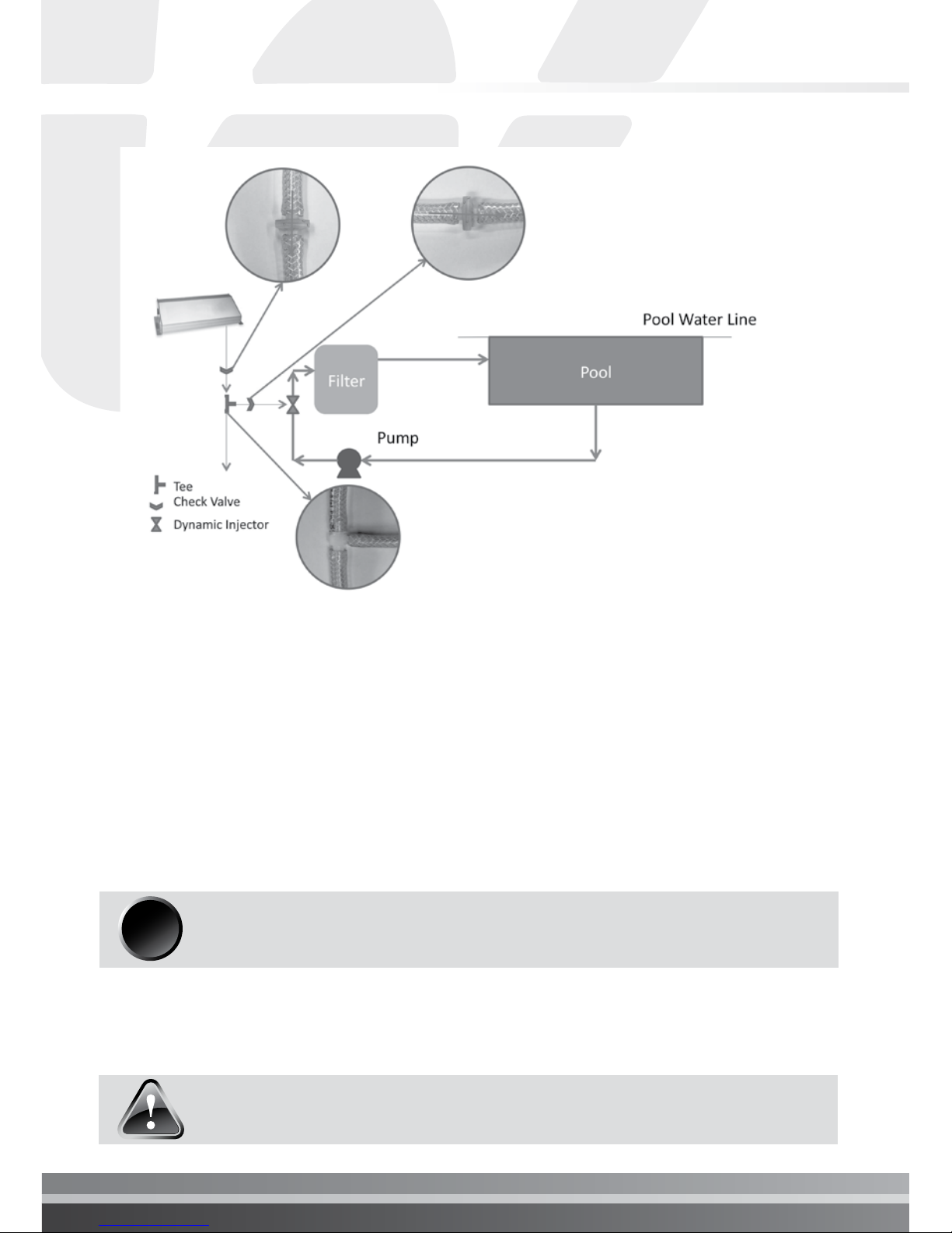
1.1 Typical Installation of Hydroxzone
¾”
Hose
¼”
Hose
¾”
Ball Valve
(If using a DE lter)
¼”
Hose
Hydroxzone
Pump
HeaterFilter
Bypass
Exit Pool
Check Valve
Bypass
Entrance
Venturi Injector
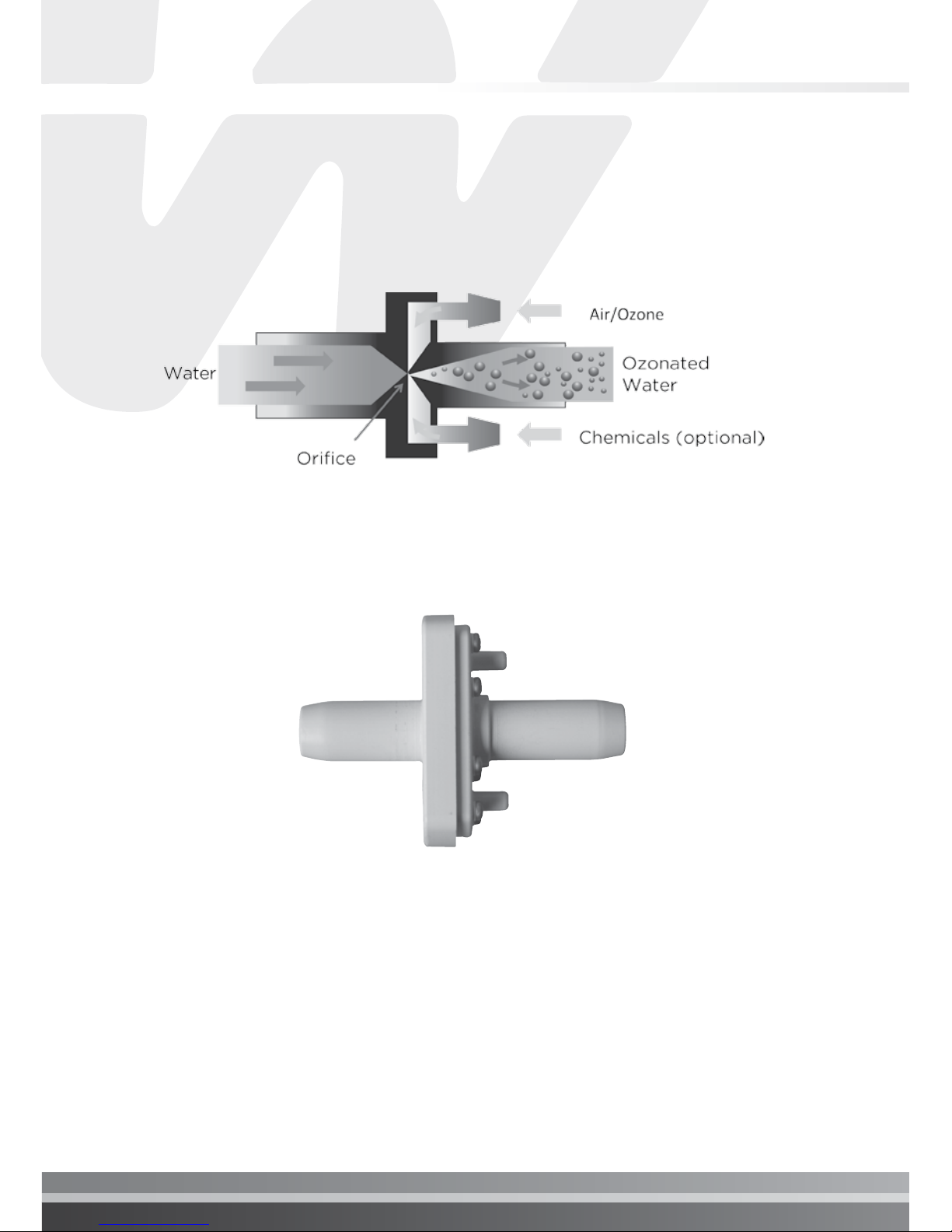
1.2 THE DYNAMIC VENTURI INJECTOR (DVI) ASSEMBLY
Hydroxzone ozone generator uses a Dynamic Venturi Injector that enhances the transfer of
ozone to the water. The injector is specially designed to minimise the pressure drop across the
system.
Figure 1.2 How the injector works
Figure 1.3 Venturi Injector

I pg 03
Hydroxzone Ozone Generator
2. INSTALLATION
2.1 PREPARING FOR INSTALLATION
I. Check for and correct all leaks in plumbing.
II. Balance the pool Water
III. Backwash the lter on retrot installation.
IV. Shock the pool. Hydroxzone must be used in combination with and approved/registered
sanitiser
V. Turn pump OFF.
VI. Locate section of plumbing where the Venturi Injector needs to be located.
VII. Venturi Injector must be installed after the lter and any other additional equipment installed
in line (e.g. heater or solar)
VIII. The unit must be mounted out of direct contact with the weather.
IX. Hydroxzone must be mounted on a wall in a horizontal orientation as shown below.
Figure 2.1 Hydroxzone Mounting Position
NOTE: The minimum recommended vacuum at the inlet of the Venturi injector is 2 L/min.
The vacuum can be measure by using a vacuum meter (Waterco’s P/N 72522813). It may
be necessary to install a Ball Valve (not included) in the main line between the Entrance and
Exit of the bypass. The Ball Valve will need to be adjusted to ensure adequate ow through
the bypass.
Multispeed pumps can alter the water ow rate through the pool system. Adjusting the
speed of a Multispeed pump will affect the water ow and the vacuum through the Venturi
Injector.
When making any adjustments to the speed of the Multispeed pump, make sure there is a
minimum vacuum of 2L/min through the venturi injector.
All pools are different. Depending on the hydraulic resistance in the pool system, running a
Multispeed pump on low speed may not create enough vacuum. If this is the case, the pump
speed will need to be increased until the minimum required vacuum is reached.

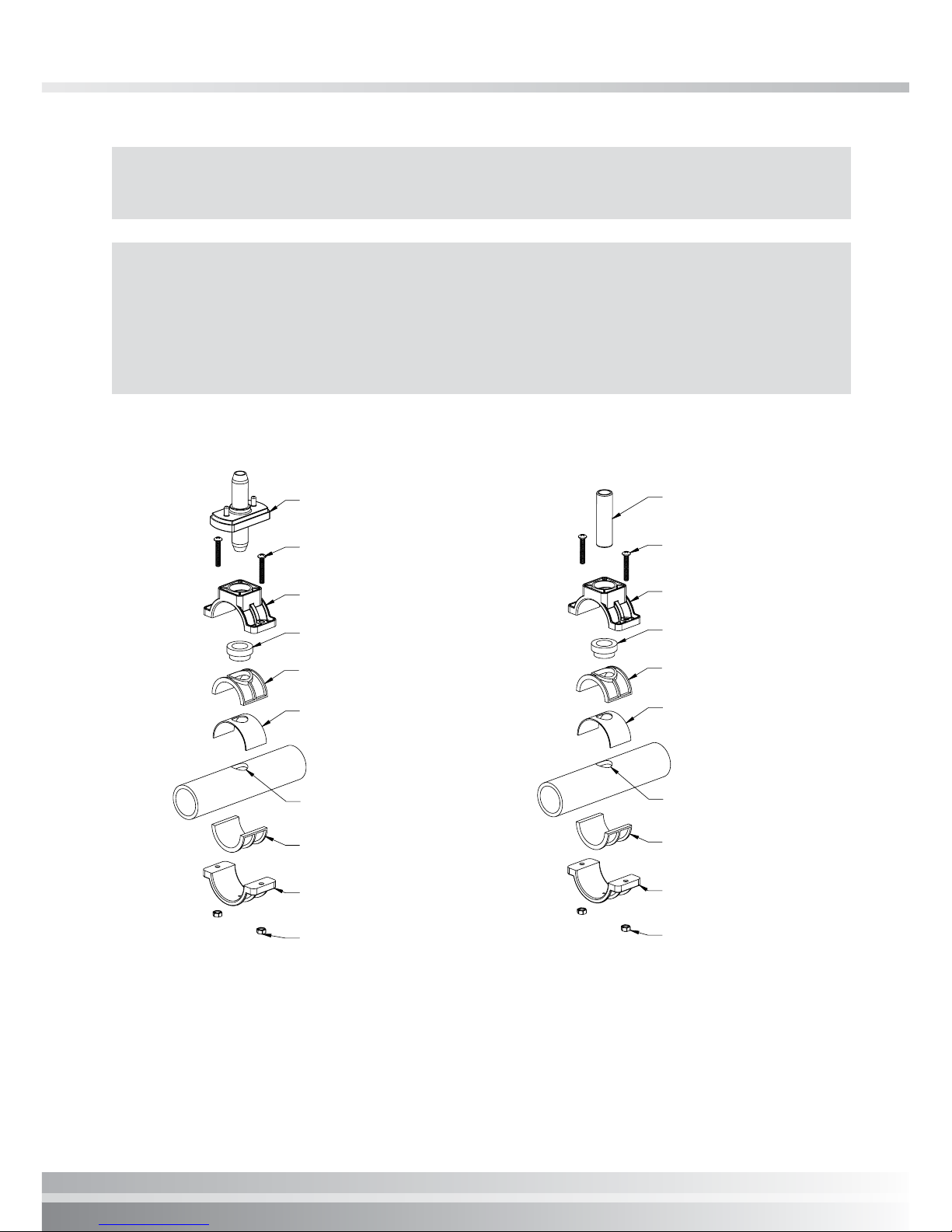
2.3 INSTALL THE SADDLE CLAMPS (BYPASS)
1. Turn pump OFF.
2. Locate section of existing plumbing in which you choose to install the ENTRANCE leg of
the bypass. Location should be in any accessible area after the pump, but before the lter
(Please refer to Figure 1.1).
3. Install Saddle Clamp Top & Bottom, (and adapters if needed), without bushing, (this will be
used as a guide for your installation hole).
4. Drill a 7/8”/22mm hole through one wall of the pipe, using power drill, being careful not to
drill too deep to avoid penetrating the opposite side of the plumbing.
5. Locate section of existing plumbing in which you choose to install the EXIT leg of the
bypass (Please refer to Figure 1.1). Location should be in any accessible area after the lter,
and heater (if equipped).
6. Repeat steps 3 & 4.
7. Remove both Saddle Clamp Assemblies.
8. Using components listed, mount one Saddle Clamp Assembly on Entrance bypass location
with the INLET side of the Venturi Injector mounted in the Saddle Clamp Bushing, (ozone
ports should be facing upward). Tighten both screws. (refer to Figure 2.2)
9. Using components listed, mount the other Saddle Clamp Assembly on Exit bypass location
with the 15mm x 75mm length (½” x 3”) PVC pipe mounted in the Saddle Clamp Bushing.
Tighten both screws. (refer to Figure 2.3)
10. Attach one end of 20mm (¾”) clear hose to Venturi Injector and secure with a metal clamp.
Attach other end of 20mm( ¾”) clear hose to 15mm x 75mm Length (½” x 3”) PVC pipe and
secure with a metal clamp.
11. Mount the Hydroxzone Ozone Generator on a wall or surface at least above maximum
water level to prevent water from contacting the electrical equipment. Unit orientation will
not affect performance.
2.2 RECOMMENDED WATER CHEMISTRY
(WATER BALANCE)
Consult the local pool professional for the correct water balance according to the swimming
pool type.
PARAMETER SUGESTED VALUE
pH 7.2-7.6
Total Alkalinity 60-200 ppm
Calcium Hardness 100 -500 ppm
Stabiliser (Sunscreen) 60-60 ppm
Phosphates <0.2 ppm
I pg 05
Hydroxzone Ozone Generator
NOTE: For 50mm pipe, do not use 40 mm adapters and gasket and turn bushings so small
end points toward Injector (for Entrance) or PVC Pipe (for Exit).
Figure 2.2
Saddle Clamp Assembly
at Bypass Entrance
Figure 2.3
Saddle Clamp Assembly
at Bypass Exit
Venturi Injector
Screw (2)
Saddle Clamp Top
Bushina
Top Adapter
Gasket
22mm (7/8”) Dia. Hole
Bottom Adapter
Saddle Clamp Bottom
1/4-20 Nut (2)
PVC Pipe
Screw (2)
Saddle Clamp Top
Bushing
Top Adapter
Gasket
22mm (7/8”) Dia. Hole
Bottom Adapter
Saddle Clamp Bottom
1/4-20 Nut (2)
NOTE: If your ltration system uses a Diatemateous Earth (DE) or cartridge lter, install a
20mm (¾”) Ball Valve (not included) in the 20mm (¾”) Hose on the output side of the Venturi
Injector as shown in Figure 1.1. This allows the bypass to be closed when back ushing or
adding DE. It may be necessary to install a Ball Valve (not included) in the main line between
the Entrance and Exit of the bypass. The Ball Valve will need to be adjusted to ensure
adequate ow through the bypass.
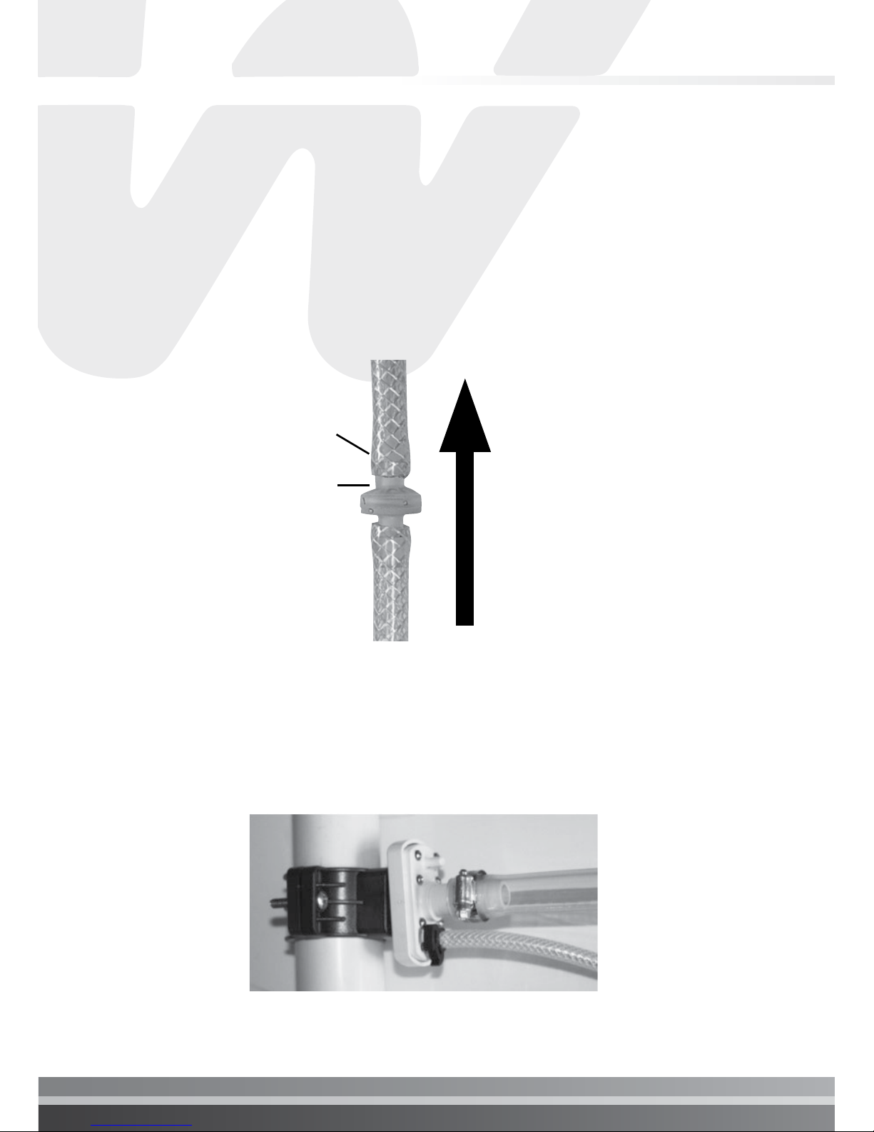
2.5 INSTALL HYDROXZONE SUPPLY TUBE
2.5.1. The Hydroxzone unit is supplied with sufcient braided supply tube which may be
cut to length. Ensure sufcient slack in the supply tube. Do not extend the length of
the braided supply tube.
2.5.2. For installations where the Hydroxzone unit is installed 400mm above the highest
point of the lter system, cut the polybraided line to a minimum of 600mm from
the Hydroxzone unit and install the check valve with the concave shape facing the
direction of the Venturi Injector, (Make sure you can blow air through the Check
Valve towards the Injector port). See Figures 2.4.
2.5.3. Cut a 150mm length of ¼” polybraided hose and connect one end to the open
ozone suction point (As shown in illustration 2.5) on the Venturi Injector and the
other end to the OUTLET side of the Check Valve.
2.4 Check Valve Orientation
Ozone
Flow
Direction
Concave
Shape
2.5 Ozone Inlet point at venturi injector
Outlet

I pg 07
Hydroxzone Ozone Generator
2.5.4. Connect the polybraided hose to the barb on the side of the Hydroxzone Ozone
Generator. (see Figure 2.6).
2.5.5. For ooded installations or where the Hydroxzone is installed below 400mm above
the highest point of the lter system, two (2) check valves and a drain must be
installed as follows: (see Figure 2.7)
I. Cut the braided supply tube a minimum of 600mm from the Hydroxzone unit.
II. Install the supplied ¼” barb Tee between the 2 sections of supplied polybraided
hose, with one end of the Tee vacant and pointing to the ground
III. Cut the polybraided hose supply line approximately 200mm further on the
Venturi Injector side of the ¼” barb Tee piece, and install a check valve with the
concave shape facing the direction of the Dynamic Venturi Injector, ensuring the
ow of air from the Hydroxzone unit to the Dynamic Venturi Injector.
IV. Cut the polybraided hose to length, ensuring a length of 200-300mm of braided
supply hose is available to make a drain off the ¼” barb Tee piece
V. Take the 200-300mm piece of polybraided hose supply and cut it in half
VI. Install the second check valve between the 2 pieces of cut supply hose
VII. Connect the 200-300mm piece of hose with check valve installed, and connect
to the base of the Tee – ensuring that the concave shape is facing toward the
vacant end of tube (Figure 2.7). Ensure this drain tube is pointing to the ground.
This will ensure water is able to drain from the supply tube.
VIII. Connect the other end of the braided supply tube to the Dynamic Venturi
Injector’s open nipple. Secure with a black plastic clip.
2.6 Connecting polybraid hose to Hydroxzone
2.6 ELECTRICAL INSTALLATION
Hydroxzone ozone generator is designed to operate on either 120 or 240 VAC, 50/60 HZ.
Connect theHydroxzone ozone generator either to the circulation pump switch or timer.
Hydroxzone ozone generator unit and circulation pump should be started simultaneously. Refer
to national electrical codes or local code grounding and installation procedures for swimming
pool equipment.
Avoid running the ozone unit on short cycles. The useful life of the UV lamp will be reduced if
stop/start operation is performed. Continuous operation of 4 to 8 hour periods per day is highly
recommended.
2-7 Installation on flooded condition
IMPORTANT: Hydroxzone must run when the pump is operational. Damage to
unit may occur if air does not pass through the unit for prolonged periods of
time.
i
CAUTION: Make sure the voltage is the same as prescribed on the side of the
HYDROXZONE ozone generator. Over voltage will void customer warranty.
I pg 09
Hydroxzone Ozone Generator
3. HYDROXZONE MAINTENANCE
The Hydroxzone ozone generator is rated to last 20,000 hours of continuous operation. Start
up and shut down cycles should be kept to a minimum to extend the life of the lamp. The U/V
lamp within the Hydroxzone will provide up to 80% of the maximum output for the system right
up until the lamp stop working.
It is good practice to check the vacuum level on the Dynamic Venturi Injector at regular intervals
to ensure there is sufcient air ow through the Hydroxzone ozone generator.
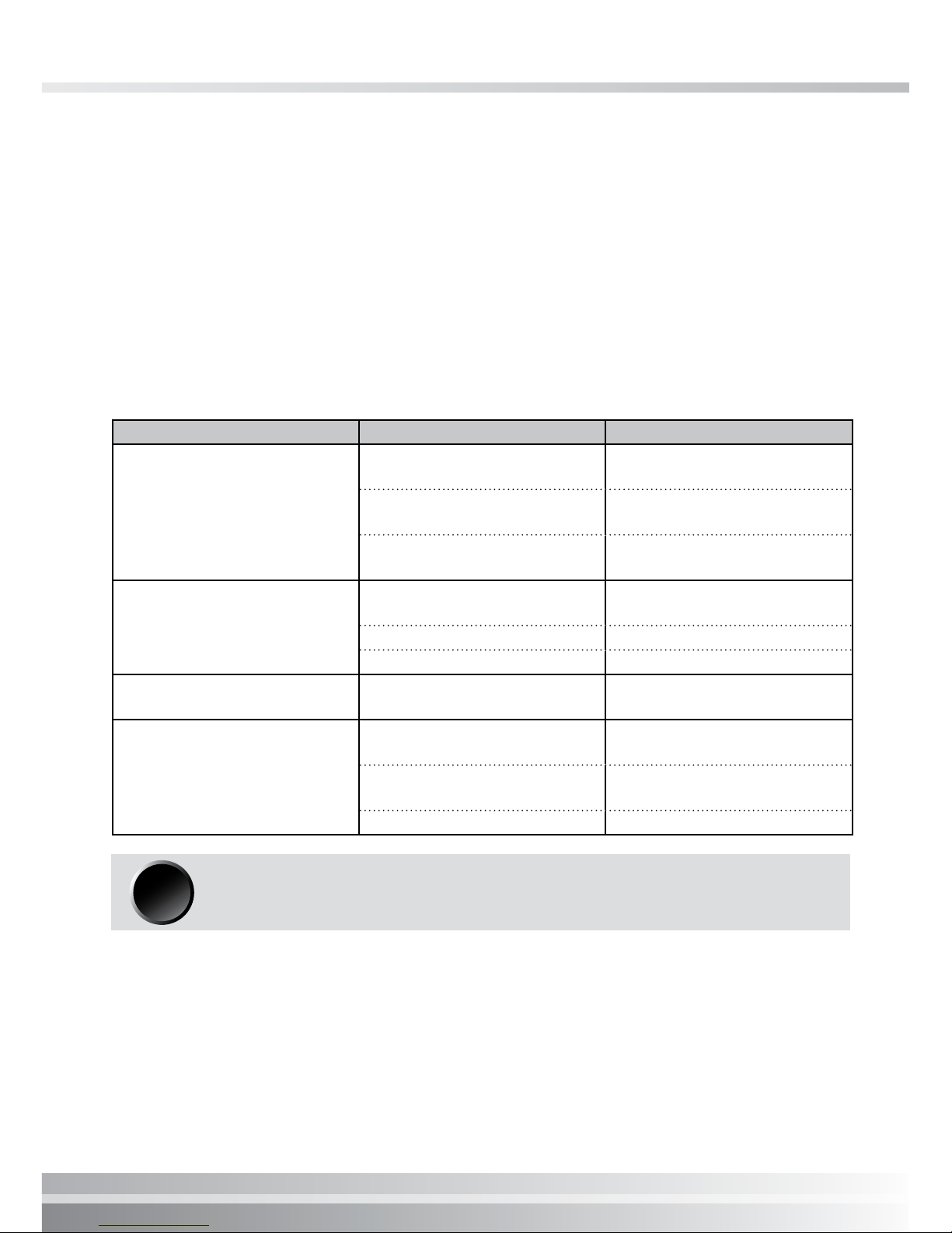
4. TROUBLESHOOTING GUIDE
NOTE: Cloudy water may occur when the Hydroxzone ozone generator is
started. Filter and backwash as necessary.
i
PROBLEM PROBLEM CAUSE REMEDY
No light from Hydroxzone
Loose wiring Check all wiring
connections
No power to unit Check voltage compatibility
Check power source
Defective ; amp or other
internal component Return unit to dealer
No bubbles from injector
or no evidence of ozone in
pool
Excessive back pressure Check for kinks or clogs in
hose or pluming
Leak in tting Replace tting
Filter not working Check lter
Water in Hydroxzone Check valve failure Verify check valve in Venturi
is operating properly
Cloudy water; foamy water;
scum
Water chemistry out of
balance
Check readings and
balance accordingly
Total dissolved solids (TDS)
level is too high
Refer to dealer for proper
water testing
Filter not working Clean or replace lter
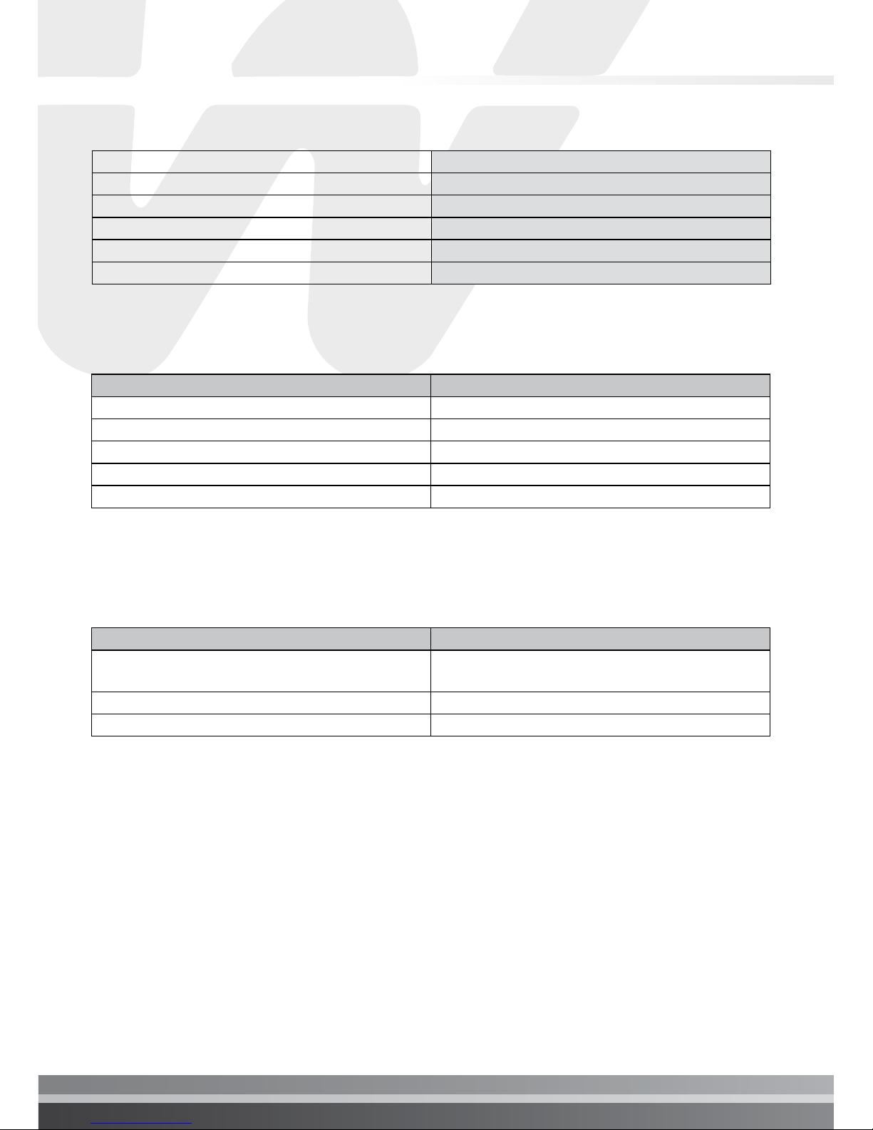
5. TECHNICAL SPECIFICATIONS
6. SPARE PARTS LIST
7. WARRANTY
Power Input (volts) 120 - 277
Frequency (Hz) 50/60
Degree of Protection IPX4
Max. Current (A) 8
Temperature Operating Range (°C) -32 to 60
Dimension (mm) 425 x 160 x 90
PART NUMBER DESCRIPTION
60137201 CHECK VALVE 1/4”
60137203 1/4” HOSE BARB TEE
60137204 PLASTIC CLIP
60137205 ¼” POLYBRAIDED HOSE
132308 DYNAMIC VENTURI INJECTOR
Component Warranty
Hydroxzone 24 months
(commercial application 12 month)
Venturi Injector 12 months
Labour 12 months
Please refer to Waterco’s Warranty terms and conditions.

I pg 11
Hydroxzone Ozone Generator

Waterco Limited ABN 62 002 070 733
(ZZB1460) 11/2014
Offices - AustrAliA
NSW - SYDNEY
(HEAD OFFICE)
Tel: +61 2 9898 8600
QLD - BRISBANE
Tel: +61 7 3299 9900
VIC/TAS - MELBOURNE
Tel: +61 3 9764 1211
WA - PERTH
Tel: +61 8 9273 1900
SA/NT - ADELAIDE
Tel: +61 8 8244 6000
ACT DISTRIBUTION
Tel: +61 2 6280 6476
Offices - OVerseAs
WATERCO (EUROPE) LIMITED
Sittingbourne, Kent, UK
Tel: +44 (0) 1795 521 733
WATERCO FRANCE
Saint Priest, France
Tel: +33 4 72 79 33 30
WATERCO (USA) INC
Augusta, Georgia, USA
Tel: +1 706 793 7291
WATERCO CANADA
Longueuil, Quebec, Canada
Tel: +1 450 748 1421
WATERCO (NZ) LIMITED
Auckland, New Zealand
Tel: +64 9 525 7570
WATERCO © LIMITED
Guangzhou, China
Tel: +86 20 3222 2180
WATERCO (FAR EAST) SDN BHD
Selangor, Malaysia
Tel: +60 3 6145 6000
PT WATERCO INDONESIA
Jakarta, Indonesia
Tel: +62 21 4585 1481
WATERCO SINGAPORE INTL PTE LTD
Nehsons Building, Singapore
Tel: +65 6344 2378
Table of contents
Other Waterco Lighting Equipment manuals

Popular Lighting Equipment manuals by other brands


Laserworld
Laserworld ES-400 RGY manual

Shadow-Caster
Shadow-Caster SCM-ZC-KIT Installation & operation manual

Philips
Philips Selecon user manual

Xoop Lighting
Xoop Lighting EL100 USER MANUAL & DATASHEET

MOB
MOB MO8940 user manual

Regent Lighting Solutions
Regent Lighting Solutions Acer installation instructions

SPARKELEC
SPARKELEC SP-3001FE/DA-D40-WH Installation and operating instructions

Equinox Systems
Equinox Systems MaxiPar Tri user manual

LumX
LumX LM 209 instruction manual

EuroLite
EuroLite LED ML-56 QCL RGBW/RGBA 18x8W user manual

thomann
thomann Ignition LED Mini Studio PAR One 40 user manual

superbrightleds
superbrightleds STN-2-COB user manual