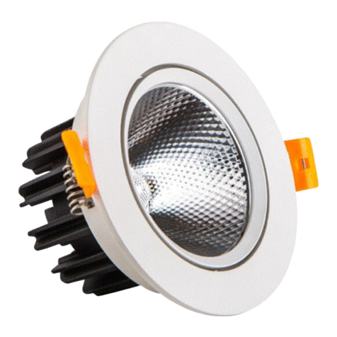
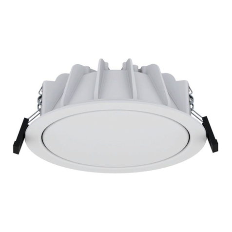
SPARKELEC SP-3001FE/DA-D40-WH User manual

INSTALLATION AND OPERATING INSTRUCTIONS
Recessed L E D Emergency Light(SP3001F E/DA-D40/D63-W H/B K)
Series product appearance unified. The functions of each MODEL is similar.
Please refer to the following table.
Battery type:
:6.4V 1500/3000mAhLiFePO4
Max Ambient temperature:60℃
Installed date:
Manufactured date:
Used date:
APPLI C AT I O N
TECHN I C AL DATA
TECHN I C AL INFORM ATI O N
PLU G IN BATTERY BEF ORE CONN ECTIN G 240V POWE R SU PPLY
During Normal operating conditions, this LED Emergency light should be connected to a Permanent Active
Circuit (not a switched active circuit). When mains power supply is available, AC provides power and charges
the built-in rechargeable batteries. The LE D Chip is always “unlit.” The LED Chip will only “light up” when
there is a cut to the mains power supply.
220-240V, 50Hz
2.5/5w
16/24 Hours
2/3 Hours
NON-maintained operation
Manual Test Switch & LED Indicator
0℃ to 40℃
LiFePO4 Battery
Recessed
IP20
Plastic
C0:D40/63 C90:D40/63
1. Input voltage:
2. DC power consumption:
3. Charge time:
4. Emergency time:
5. Operation:
6. Function:
7. Working temperature:
8. Battery:
9. Mounting:
10. I P rating:
11. Material:
12.Classification:
85
20
SP3001FE/DA-xx-yy series
Charging mode: Max.4 W 220-240 V 50/60 Hz
Emergency lighting mode: 6.4 V battery,2.5/5W
Battery supply: 1500/3000 mAh, 6.4 V d.c. .LiFePO4
Cl. II, IP20, ta 0 - +40℃, Non-maintained, 2 hours duration
The ”xx” in the type designation can be D40 or D63,
indicating different emergency luminaire:
xx=D40
xx=D63
The “yy” can be “WH” or “BK”, indicating the color of housing.
yy = WH: white; yy = BK: black
-1-
Output lumen
Model No.
200lm
SP-3001 FE/ D A-D 40 -WH
200lm
Input Voltage Charge
Time
Discharge
Time Operation Emergency Mode
Battery DC Power
Charging mode
Classfication
16/24 Hours 2/3 Hours NON-Maintaine d 2.5W
220-240V 50/60Hz
4W
D40
16/24 Hours 2/3 Hours LiFe PO4, 6.4V 1.5 Ah
NON-Maintaine d 2.5W
220-240V 50/60Hz
4W
D40
LiFe PO4, 6.4V 1.5 Ah
SP-3001 FE/ D A-D 40 -BK
400lm
SP-3001 FE/ D A-D 63 -WH
400lm
16/24 Hours 2/3 Hours NON-Maintained 5W
220-240V 50/60Hz
4W
D63
16/24 Hours 2/3 Hours LiFe PO4, 6.4V 3Ah
NON-Maintaine d 5W
220-240V 50/60Hz
4W
D63
LiFe PO4, 6.4V 3Ah
SP-3001 FE/ D A-D 63 -BK
13.SP3001-FE/DA FE: Standard ; DA: with DALI function

PREC AUTION S
This product must be only installed by a Licensed Electrician. Please make sure the mains supply is isolated
before commencing installation. Check the unit labels for correct supply voltage and frequency.
INSTAL L AT ION INS T RUCTIO N S
2. B dia-cut
solution:
Step 1. Remove the product from the box and inspect it for any damage. If you believe the product
to be damaged or otherwise unsound, DO NOT install the fitting.
Please pack it back into its box and return it to the place of purchase for replacement.
Step 2. Choose the LED panel size that is suitable for your application.
65-70mm cut out for the 85mm panel or 75-125mm for the 140mm panel.
Note that this product can be installed into an existing cut out in the ceiling ranging from
65mm to 125mm.
For the smaller 65-75mm panel, remove outer ring by twisting the outer ring out of its
locking position and sliding the outer ring down the loom.
Step 3. Put the inverter and battery into the ceiling, fix it onto the ceiling by self-tapping screws.
Step 4. Connect the LED panel connector.
Step 5. Connect the battery connector.
Step 6. Once the L E D Emergency Light is Installed/Plugged Into Mains Power, ensure the loom
goes through the cutout into the ceiling. Pull back the two spring clips so they can fit through the
ceiling cutout. Release the spring clips, ensure the dish is secure and flush up against the ceiling.
Step 7. Turn on the mains power, check if the LED Indicator on the LED Emergency Light is “ON”,
if not check if the connectors between the inverter and the LED Emergency and/or battery is
securely connected and the mains power is turned on. Press the “TEST” Button, if the LED Chip
“light up” then the installation is successful and complete.
Step 8. Finally, THE INSTALLER MUST Charge the fitting for a minimum of 24 Hours without
disconnecting Power.
AC 220V-240V
65 - 75 mm opening
75 - 125 mm opening
AC 220V-240V
LED panel dia.: 140 mm
LED panel dia.: 85 mm
BATTERY
BATTERY
1. A dia-cut
solution:
-2-
This is a mains powered product. Before Installation or maintenance, please make sure power supply is
isolated. If the external flexible cable of this luminaire is damaged, it should only be replaced by a licensed
electrician or equivalent qualified person to avoid any safety hazards.
This luminaire is intended only for mounting in locations where the plug and sockets are protected from
unauthorised disconnections.
SAFE T Y

REPLACING THE BATTERY
1, Using only the battery recommended on the label found on the surface of the inverter. NO other
battery will work in this fitting, other than the type listed.
2, Make sure the main supply is isolated before commencing the replacement.
3, Take out the LED panel from the ceiling.
4, Unplug the AU plug, disconnect the battery terminal.
4, Then connect the new battery with the same specification.
4, Reconnect with the main supply, check the indicator and the LED statue.
BATTERY LIFE
The designed lifespan of the battery installed in this product is 2 Years, the battery should be replaced
after this time. To maintain the economical life of this product it is required that the battery be
discharged and replaced at least once every 6 Months. The battery life can be reduced if the battery is
not discharged in accordance with requirements of AS 2293.
Regularly discharging/cutting mains power i.e. During Construction Stage, will SIGNIFICANTLY
shorten the battery’s lifespan and damage the battery. Product failure as a result from this practice is
strictly NOT COVERED U N D ER WARRANTY AND WILL AUTOMATICALLY V O I D PRODUCT
WARRANTY.
WARNING: Care should be taken when replacing the battery, because this lamp is powered by a battery
and an operated inverter when disconnected from the mains supply.
Regular discharge duration to be checked in accordance with emergency lighting regulations.
MAI NTE N A NC E
When this fitting is permanently connected to the mains supply you will need to charge the battery for
24 Hours. Once the battery is fully-charged,you will need to conduct a manual discharge test as per the
requirement of AS/N ZS 2293. At the time of printing, the standard requires that new fittings operate in
emergency mode for at least 2 Hours for their first discharge test.
Further tests are to be carried out at intervals of not more than 6 Months. It is important that you keep
records of the initial test and ongoing tests in the building’s emergency service log book. If the fitting is not
to be permanently connected to the mains supply at the time of installation, you must give it the mandatory
2 Hours test when you connect it permanently to the mains supply.
TES TIN G P REC AU TIO NS
Test Switch
A Test Switch is provided to simulate a supply circuit failure. Press and Hold the test switch, the LED Chip
will “Light up” in Emergency Mode, After Releasing the Test Switch, the LED Chip will become “unlit” (back
to normal)
The lamp does not on when the
test switch is pressed.
Lamp lights, but only temporarily, when test switch is
pressed or when main power supply is turned off.
▪ Lamp is damaged
▪ Lamp is not inserted properly
▪ Battery pack is damaged
▪ Battery pack not fully charged
▪ Battery pack is damaged
-3-
If you have installed and connected the fitting as per the instruction contained within this manual and the light
fails to work properly, please use the following table as a guide to fixing the problem.
FAU LT
POS S IBL E C AU S ES
Indicator is not lit
▪ AC Supply is not connected
▪ AC Supply turned off
▪ Battery plug not connected to battery pack
BATTERY LIFE
The designed lifespan of the battery installed in this product is 2 Years, the battery should be replaced
after this time. To maintain the economical life of this product it is required that the battery be
discharged and replaced at least once every 6 Months. The battery life can be reduced if the battery is
not discharged in accordance with requirements of AS 2293.
DALI (Digital Addressable Lighting Interface)
DALI is widely acknowledged as being an open protocol as defined under IEC 62386 and is designed only
for communication in lighting systems.
SP3001DA -D40/D63-WH/BK with DALI functionality comply with DALI standard IEC 62386.
The DALI wiring consists of additional 2 terminals in the ceiling bracket marked as “DA” and “DA” for DALI
control wires apart from the mains terminals, ie: L, N and E.
Note: Mains or mains carrying cables should not to be connected to DALI terminals or DALI control wires.

Australian & New Zealand Classifications
Luminaires shall be classified as at least one of the following:
a) Non-IC
b) Do-not-cover
c) C A90
d) C A 135
e) I C
f) I C-4
a) Non-IC luminaire
a recessed luminaire that cannot be abutted against or covered by normally flammable materials or used in
installations where building insulation or debris is, or maybe, present in normal use.
NOTE: This classification is not suitable for residential installations.
b) Do-not-cover luminaire
a recessed luminaire that can be used where normally flammable materials, including insulation, are or may be
present, but can not abutted against any material and cannot be covered in normal use,
c) C A 90 luminaire
a recessed luminaire that can be abutted against normally flammable materials, including building insulation, but
cannot in normal use. Building elements, building insulation or debris have limited access to the heated parts of
of the luminaire.
d) CA 135 luminaire
a recessed luminaire that can be abutted against normally flammable materials, including building insulation, but
cannot in normal use. Building elements, building insulation or debris have some access to the heated parts of the
luminaire.
e) I C luminaire
a recessed luminaire that can be abutted against normally flammable materials, including building insulation, and
can be covered in normal use. Building elements, building insulation or debris have limited access to the heated
parts of the luminaire.
f) I C-4 luminaire
a recessed luminaire that can be abutted against normally flammable materials, including building insulation, and
can be covered in normal use. Building elements, building insulation or debris have restricted access to the heated
parts of the luminaire. This classification of recessed luminiaire is effectively a sealed unit that has a restricted flow
of air between the habitable room the luminaire emits light into and the void/space where the main body of the
luminaire is located.
RISK O F F I R E -REQU I R E D C LEAR A N C E F ROM STRUCTURAL MEMB E R S
AND BU I L D I NG ELE M E N T S
HCB=20mm M IC=20mm SCI-20mm S CB=20mm
-WARNING-
RI SK O F OVERHEATING O R F I R E I F THE CLE AR AN CE D IS TA NC ES A RE COMPROMISED.
LA MP I S NOT-RE PL AC EA BL E
-4-
N5667
Tested By
FTa 0℃-40℃
IC
AB UT TED &
CO VE RE D
This manual suits for next models
3
Popular Lighting Equipment manuals by other brands
IKEA
IKEA tradfri manual
Laserworld
Laserworld Club Series manual
Vision & Control
Vision & Control TZB38-IR850-P-SL Instructions for use
Hella
Hella Luminator 4000 Compact LED Installation instruction
Vision & Control
Vision & Control LDLF60x540-R633/24V Instructions for use
Regent
Regent WZT1500 instruction manual


