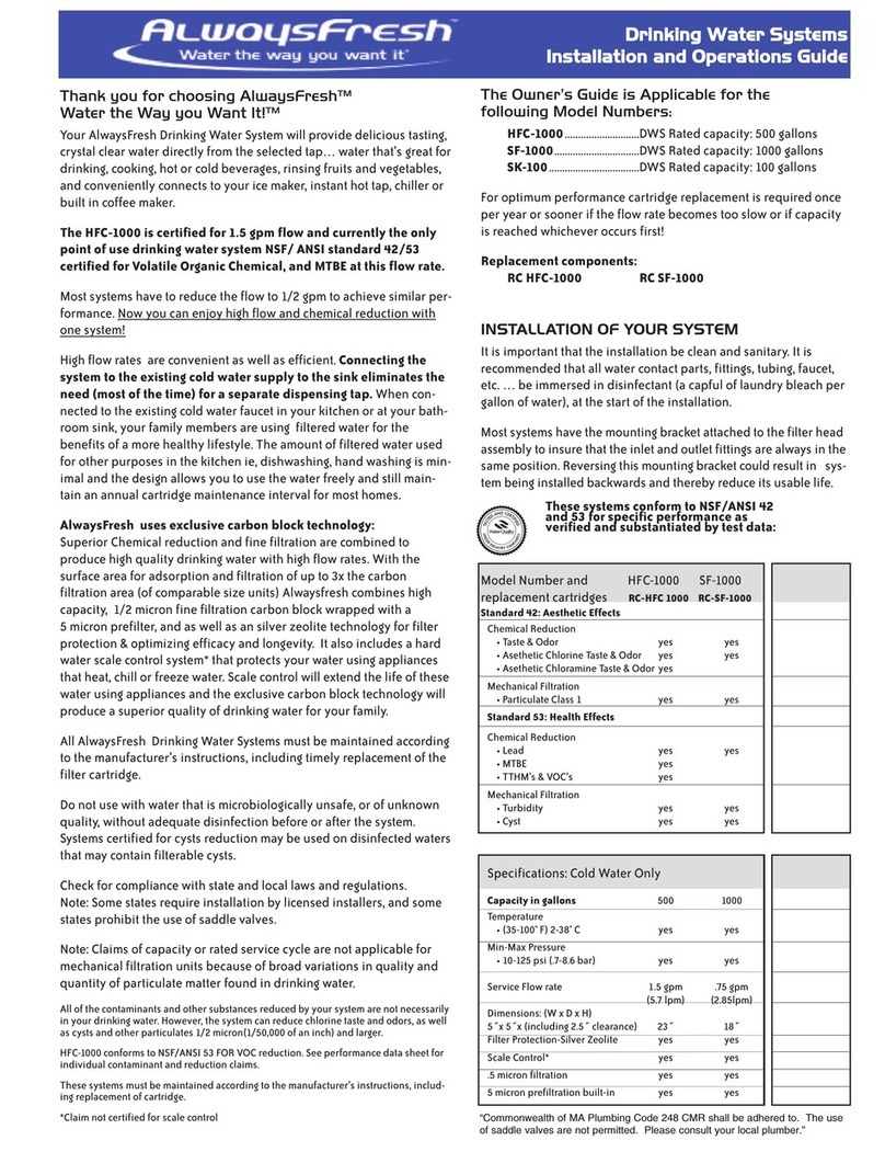
Waterline Technology AlwaysFresh LF-1250 User manual

Thank you for choosing AlwaysFresh Water the Way you Want It!
Your AlwaysFresh Drinking Water System will provide delicious tasting, crystal clear
water directly from the selected tap… water that’s great for drinking, cooking, hot or
cold beverages and, rinsing fruits and vegetables. It conveniently connects to your ice
maker, instant hot tap, chiller or built in coffee maker.
The HFC-1000 is certified for 1.5 gpm flow and currently the only point of use drinking
water system NSF/ANSI standard 42/53 and NSF P473 certified for Volatile Organic
Chemical, MTBE, Cysts, ead & PFOA/PFOS reduction at this flow rate.
Most systems have to reduce the flow to 1/2 gpm to achieve similar performance.
Now you can enjoy high flow and chemical reduction with one system!
High flow rates are convenient as well as efficient. Connecting the system to the exist-
ing cold water supply to the sink eliminates the need (most of the time) for a separate
dispensing tap. When connected to the existing cold water faucet in your kitchen or at
your bathroom sink, your family members are using filtered water for the benefits of a
more healthy lifestyle. The amount of filtered water used for other purposes in the
kitchen ie, dishwashing, hand washing is minimal and the design allows you to use the
water freely and still maintain an annual cartridge maintenance interval for most homes.
AlwaysFresh uses exclusive carbon block technology: Superior Chemical reduction and
fine filtration are combined to produce high quality drinking water with high flow rates.
With the surface area for adsorption and filtration of up to 3x the carbon filtration area
(of comparable size units) Alwaysfresh combines high capacity, 1/2 micron fine filtration
carbon block wrapped with a 5 micron prefilter, as well as silver zeolite technology for
filter protection & optimizing efficacy and longevity. It also includes a hard water scale
control system* that protects your water using appliances that heat, chill or freeze
water. Scale control will extend the life of these water using appliances and the exclu-
sive carbon block technology will produce a superior quality of drinking water for your
family.
All AlwaysFresh Drinking Water Systems must be maintained according to the
manufacturer’s instructions, including timely replacement of the filter cartridge.
Do not use with water that is microbiologically unsafe, or of unknown quality, without
adequate disinfection before or after the system. Systems certified for cyst reduction
may be used on disinfected waters that may contain filterable cysts.
Check for compliance with state and local laws and regulations.
Note: Some states require installation by licensed installers, and prohibit the use of
saddle valves.
Note: Claims of capacity or rated service cycle are not applicable for mechanical filtra-
tion units because of broad variations in quality and quantity of particulate matter found
in drinking water.
All of the contaminants and other substances reduced by your system are not neces-
sarily in your drinking water. However, the system can reduce chlorine taste and odors,
as well as cysts and other particulates 1/2 micron(1/50,000 of an inch) and larger.
HFC-1000 is certified to NSF/ANSI 53 MTBE,VOC & Turbidity reduction. See perform-
ance data sheet for individual contaminant and reduction claims.
These systems must be maintained according to the manufacturer’s instructions, includ-
ing replacement of cartridge. *Claim not certified for scale control
The Owner’s Guide is Applicable for the following Model Numbers:
HFC-1000...........................................DWS Rated capacity: 500 gallons
SF-1000..............................................DWS Rated capacity: 1000 gallons
F-1250..............................................DWS Rated capacity: 1250 gallons
HF-6000 ...........................................DWS Rated capacity: 3000 gallons
HF-20000 & HF-20000-S...................DWS Rated capacity: 20000 gallons
For optimum performance cartridge replacement is required once per year or sooner if the
flow rate becomes too slow or if capacity is reached.
Replacement Cartridges:
RC HFC-1000.....RC SF-1000.....RC- F-1250 ..... RC-HF-6000 ....RC-HF-20000
RC-HF-20000-S
INSTA ATION OF YOUR SYSTEM
It is important that the installation be clean and sanitary. It is recommended that all water
contact parts, fittings, tubing, faucet,etc. … be immersed in disinfectant (a capful of
laundry bleach per gallon of water), at the start of the installation.
Most systems have the mounting bracket attached to the filter head assembly to insure that
the inlet and outlet fittings are always in the same position. Reversing this mounting bracket
could result in system being installed backwards and thereby reduce its usable life.
CERTIFICATION OF PERFORMANCE
These Systems certified by WQA to CSA B483.1, NSF/ANSI 42/ 53,and by
IAPMO R&T to CSA B483.1, NSF/ANSI 42/53, NSF protocol P473 for specific
performance claims as verified and substantiated by test data, as enumerated
below and on individual performance data sheets.
Refer to www.wqa.org or www.iapmort.org data bases for details of certification.
Certified by the Water Quality Association to WQA/ASPE/ NSF/ANSI S-803 for
Sustainability(2)
Model Number HFC-1000 SF-1000 LF-1250 HF-6000L HF-20000-SHF-20000
Replacement Cartridges RC-HFC-1000 RC-SF-1000 RC-LF-1250 RC-HF-6000L RC-HF-20000-SRC-HF-20000
Standard 42: Aesthetic Effects
Chemical Reduction
*Taste & Odors yes yes yes yes yes yes
* Aesthetic Chlorine yes yes yes yes yes yes
Mechanical Filtration
*Particulate Class 1 yes yes yes yes(1) yes(1) yes(1)
Standard 53: Health Effects
Chemical Reduction
*Leadyesyesyesyes
*MTBE yes
*TTHM's yes
*VOC's yes
yes
Mechanical Filtration
*Turbidity yes yes yes(1) yes(1) yes(1)
*Cysts yes yes yes yes yes yes
Specifications Cold Water Only
Rated Capacity in Gallons 500 1000 1250 3000 20000 20000
Temperature
*35-100◦ F (2-38◦ Cyes yes yes yes yes yes
Min-Max Pressure
*30-125 psi (2.1-8.6 bar)yes yes yes yes yes yes
Service flow Rate gpm / (lpm) 1.5/5.7 0.75/2.80.5/1.9 1.67/6.31.67/6.31.67/6.3Dimensions (W x D X H)
5" x 5" x (including 2.5" clearnance) 23" 18" 12" 18"23" 23"
Filter Protection - Silver Zeolite yes yes yes no yes yes
0.5-1 Micron filtrationyesyesyesyesyesyes
5 micron prefiltration built-in yesyesyesyes
Scale Control (1) yes yes yes yes
(1)not certified by WQA
*PerFluorooctanoic acid (PFOA) &
PerFuorooctane sulfonate (PFOS

INSTALLATION INSTRUCTIONS
AlwaysFresh System mounting/location details: The systems are designed
for under the sink installation. Optional basement or utility area is OK,
however additional 3/8˝ tubing and fittings will be required.
1) Install filter cartridge into the head assembly using cartridge installation
instructions.
a. Using a water proof marker write the date installed on the cartridge
label.
b. Install filter inlet/outlet Swivel fittings on head assembly
c. Apply 3-4 wraps of Teflon tape onto 3/8˝ NPT Male threads
2) Screw fittings into female 3/8˝ NPT fittings (inlet & outlet) on head
assembly until finger tight (approximately one-two turns).Caution: Models
HFC-1000, SF-1000 use white swivel
3) To insure seal continue one to two more turns past finger tight.
4) Total number of turns from start to finish need not exceed five turns. Do
not over tighten.
5) Position system with cartridge, head assembly (with fittings) and mount-
ing bracket to desired location. It is recommended to mount top of bracket
23˝ off floor to accept our longest replacement cartridge (HFC-1000)
a. Allow a clearance of 2-1/2˝ minimum below cartridge for removing and
replacement.
b. Allow sufficient clearance on each side for inlet/outlet fittings to swivel
freely 180 degrees.
c. Use a dark colored marker to mark positions of screw
eyelets (mounting bracket) on mounting wall.
d. Insert screws into wall at marks, which will hold the filter leaving
enough screw head to insert mounting bracket into eyelets. (note wood
screws provided)
NOTE: Unit can weigh up to 10 lbs. with water so be sure the wall is strong
enough to hold the weight.
e. Secure complete system by tightening the mounting bracket
screws.
Select the installation choice below for using: Existing cold water sink faucet
or Separate dispensing tap !
INSTA ATION USING EXISTING CO D WATER SINK FAUCET
A: Installing the water supply fittings: Turn off cold water supply line. If cold
water line does not have a shut-off valve under the sink, you should install
one.
1) Open the cold water faucet and allow all the water to drain from line.
2) For cold water lines that use tubing (plastic or soft copper)follow these
instructions. For flexible hose installation that uses 3/8˝ NPS compression
connection, go to step 8. Do not complete steps 3-7.
3) Cut tubing a minimum of 2˝ above the existing cold water stop valve and
remove any burrs.
4) Mark this length of tubing 3/4˝ from top as a guide for inserting into the
new supply valve elbow’s quick connect fitting.
5) Insert tubing into bottom of the new supply valve elbow to insertion line.
6) Mark the supply line previously connecting the cold water to the faucet
3/4˝ from the bottom as a guide for inserting into the union fitting.
7) Insert this tube into one end of union connecter fitting to the insertion
line.
8) For Flexible hose installation from step 2.
9) Disconnect cold water line from existing 3/8˝ NPS stop valve
10) Apply 3-4 wraps of Teflon tape onto Male threads of the existing 3/8˝
NPS Stop valve male fitting.
11) Connect Faucet adapter female fitting to existing stop valve. Do not over
tighten.
12) Push tube end of Faucet Adapter female fitting into bottom of new sup-
ply valve
13) Apply 3-4 wraps of Teflon tape onto male threads of the flexible hose fit-
ting currently connected to the cold sink faucet.
14) Connect this hose to the 3/8˝ Faucet male adapter. Do not over tighten.
15) Push tube end of Faucet adapter into union connector.
B: Connecting the water supply and existing sink faucet to Filter.
INLET Fitting:
1) Determine the length of plastic tubing (3/8˝ tubing 5´ supplied with sys-
tem) needed to connect the inlet (left side) of the filter with the supply valve.
a.Be sure to allow enough tubing to prevent kinking and cut the tubing
squarely and remove all burrs. Place a mark 3/4˝ from end of tubing.
b.Wet tubing with water and insert into outlet of supply valve (3/4˝) until
mark is flush with fitting.
c. Place a mark on the other end 3/4˝ from end of tubing.
d.Insert tubing into inlet of system fitting to insertion mark.
OUTLET Fitting:
2) Determine the length of tubing (3/8˝ tubing supplied) with system to
make the connection from the outlet fitting of filter to 3/8˝x 3/8˝ union fitting.
A 3´ minimum length is suggested to connect accessories into this line.
a. Place a mark 3/4˝ from end of tubing.
b. Wet tubing with water and insert into union until mark (3/4˝) is flush
with union fitting connected to tube/hose.
3) Double check that the water supply is directed to the filter inlet and the
outlet is directed to the sink cold faucet line.
Go to Placing Filter in Operation section
INSTALLATIONS USING SEPARATE DISPENSING TAP
A: Installing the Water supply fittings: Turn off cold water supply line. If cold
water line does not have a shut-off valve under the sink, you should install
one.
1) Turn on the cold water faucet and allow all the water to drain from line.
2) For cold water lines that use tubing (plastic or soft copper follow these
instructions. For flexible hose installation that use 3/8˝ NPS compression
connection go to step 6. Do not complete steps 3-5.
2

3) Cut 1-3/8˝ section out of tubing a minimum of 2˝ above the existing
cold water stop valve and removes any burrs.
4) Mark both sections 3/4˝ from the ends as a guide for inserting into the
new supply valve quick connect fittings.
5) Insert tubing into bottom & top of this valve to insertion line.
6) For Flexible hose installation from step 2.
7) Disconnect cold water line from existing 3/8˝ NPS stop valve
8) Apply 3-4 wraps of Teflon tape onto Male threads of the existing 3/8˝
NPS stop valve.
9) Connect the faucet female adapter to existing stop valve. Do not over
tighten.
10) Push tube end of Faucet female adapter into bottom of the new sup-
ply valve to insertion line.
11) Apply 3-4 wraps of Teflon tape onto male threads of Faucet male
adapter.
12) Using the supply line flexible hose previously connecting the cold
water line connect the Faucet male adapter. Do not over tighten.
13) Push tube end of faucet male adapter into top of the new supply valve
to insertion line.
B: Location details for New Separate Dispensing Tap
1) This tap should be positioned with function, convenience, and appear-
ance in mind. An adequate flat area is required to allow faucet base to rest
securely. Most sinks have pre-drilled 1-3/8˝ or 1-1/2˝ diameter holes that
may be used for this tap installation. If these holes cannot be used or are
in an inconvenient location, it will be necessary to drill a new hole. A 1-1/4˝
hole is recommended.
a. Waterline has hole saws available for porcelain over cast iron and
for stainless or fiberglass type sinks.
b. The stainless hole saw has also worked effectively for hard
surface counter tops which use a carbide tip for drilling.
c. Do not use either of these saws for marble, granite or other sur-
faces without consulting the manufacturer or dealer where purchased.
d. Drilling may result in damage to your sink or countertop and
Waterline is not responsible for any such damage. Consult a plumber,
countertop manufacturer or sink manufacturer for instructions.
NOTE: You may wish to use the existing cold water sink faucet installation
section in lieu of a separate dispensing tap if this become a problem.
C: Mounting the Dispensing Tap
Consult the dispensing tap instructions. NOTE: A 3/8˝ tube x 7/16˝ faucet
adapter fitting is supplied with this system to make a quick connection to
this faucet and outlet of filter using the union fitting connected to filter out-
let 3/8˝ tubing. NOTE: Install the filter to thread shank on faucet.
D: Connecting the water supply to Filter
INLET Fitting:
1) Determine the length of plastic tubing (3/8˝ tubing 5´ supplied with sys-
tem) needed to connect the inlet (left side) of the filter with the supply
stop valve.
a. Be sure to allow enough tubing to prevent kinking and cut the tub-
ing squarely and remove all burrs. Place a mark 3/4˝ from end of tubing.
b. Wet tubing with water and insert into outlet (side fitting) of
supply valve until 3/4” mark is flush with fitting.
c. Place a mark 3/4˝ from other end of tubing.
d. Insert tubing into fitting inlet of system to insertion mark.
OUTLET Fitting:
1) Insert union connector into faucet adapter fitting 3/4˝.
2) Determine the length of tubing (3/8˝ tubing supplied) with system to
make the connection from the outlet fitting of filter to 3/8˝ union connec-
tion which is also connected to the faucet adapter fitting on bottom of dis-
pensing tap.A 3´ minimum length is suggested to connect accessories to
this line.
a. Place a mark 3/4˝ from end of tubing.
b. Wet tubing with water and insert into union connecter until mark
(3/4˝) is flush with this fitting.
3) Double check that the water supply is directed to the filter inlet and
the outlet is directed to the sink cold faucet line.
P ACING FI TER IN OPERATION
Turn on water supply valve and check for leaks.
1) eave the cold water faucet at the sink turned off to allow system to
come up to pressure. Recheck for leaks after 3 minutes.
2) Turn on filter water dispensing faucet and allow water to run until
clear. Normally 2-3 minutes is adequate.
CONNECTING ADDITIONAL ATER USING APPLIANCES TO THIS
FILTERING SYSTEM AND OPTIONAL SURGE TANK
You can readily connect your refrigerator ice / water dispensing system to
this filter. Connect a 3/8˝ reducing tee in the line between the filter and
faucet (see instruction example)
1) If your refrigerator is equipped with a built-in filter already consult
your instruction manual for by-pass instructions.
There will be no need to use both and one does not want to leave in the
refrigerator filter without replacing it periodically so you will want to bypass
it at this time.
2) Multiple tees can be inserted to service other appliances and loca-
tions. Consult the appliance instructions for inlet tube size!
a. Built-in coffee makers
b. Instant Hot taps/under counter chillers
c. Prep sink, other sink locations that you can conveniently run a 3/8˝
line to service the existing sink faucet
3) Optional Surge Tank AP-8002
a. Install 3/8” tee between filter and dispensing faucet
b. Install 3/8” x 1/4” NPT shut off valve to storage tank
c. Position tank in convenience location near filter system
d. Field cut 3/8” tubing to lenght and install in 3/8” tee and storage
tank shut off valve. Check for leaks!!! This will provide filtered water
from storage tank and filter system to increase flow rate out of dispensing
faucet.
Replacement Cartridge Programs: Waterline offers several programs
that are designed to insure your system is properly maintained.
RCRS: Replacement Cartridge Reminder Service, You can enroll to be
notified every 11 months that it is time to change your cartridge. Go to
www.waterlinetechnology.com click on Cartridge Replacement icon and
then click “Register your product” to enroll.
ACDP: Automatic Cartridge Delivery Program, Waterline will send you a
new replacement cartridge of your choice every 12 months.Save 15% on
your cartridge under this program
ii. ock in the current list price for up to 3 years
iii. Automatically enrolled in our extended lifetime warranty (E W)
iv. Go to www.waterlinetechnology.com click on Cartridge
Replacement program and then select to enroll on line or download
the enrollment form.
You may also call our office at 1-800-522-3949 to enroll in either
program.
3

F
3/8˝ Plastic tubing
with a minimum
rating of 120 psi
B
Outlet
Filter
hea
A
Inlet
Ice maker tee (or er separate)
or other water using appliances inclu ing
AP-8002 surge tank
E
G
D
Recommen e
Installation:
Top of bracket shoul
be 23˝ above cabinet floor
to accept our longest
cartri ge
Incoming col water
line*
Stop
valves
Plug (not
inclu e )
Supply
T-a apter
Sprayer hole or
specially cut fil-
ter faucet hole
Sprayer hose
connection
3/8˝ Plastic tubing
with a minimum
rating of 120 psi
Filter
hea
Recommen e
Installation:Top of bracket
shoul be 23˝ above cabinet
floor to accept our longest car-
tri ge
Incoming col
water line*
Use a connection that complies with state & local plumbing co es. * Installation kits inclu e a shut-off valve.
Ice maker tee (or er separate)
or other water using appliances
inclu ing Surge tank *
I
E
F
B
A
Inlet
Outlet
Stop
valves
H
G
D
Connection to Separate
Dispensing Tap
C
C
4
Connection to Existing
Cold Sink Faucet
Parts List Order AP-IK-SDT-38
Key PN# Description Qty.
APH-65096018WP2 Inlet Fitting (1) 3/8˝x3/8˝ Male NPTF
swivel elbow, white
B Q0620616-B Outlet Fitting (1) 3/8˝x3/8˝ Male NPTF
swivel elbow, black with 1.5
gpm flow restricter for
HFC-1000 an SK-100
BPH-65096018WP2*Outlet Fitting (1) 3/8˝x3/8˝ Male NPTF
swivel elbow, white for
SF-1000
C Misc AlwaysFresh™ System (1)
D** PP6VTU6-MG Water Supply Valve (1) 3/8˝ tube or com
pression w/ball valve
E** AW6TFA9-MG Tube Faucet A apter female (1) 3/8˝ tube or compression
F** AW6TAF9-MG Tube Faucet A apter male (1) 3/8˝ tube or compression
G PH-63066000WP2 Union Connecter (1) 3/8˝x 3/8˝
H** AW6TFA7-MG Tube Faucet A apter female (1) 7/16˝x 24 threa s x 3/8˝
Fitting supplie for ispensing faucet
I MISC Dispensing Faucet – Or er separately
* Outlet Fitting for SF-1000 only
**AP-IK-SDT-38 installation kit require in a ition to stan ar parts with system
Parts List: These parts included with
installation kit for system
Key PN# Description Qty.
APH-65096018WP2 Inlet Fitting (1) 3/8˝x3/8˝ Male NPTF
swivel elbow, white
B Q0620616-B Outlet Fitting (1) 3/8˝x3/8˝ Male NPTF
swivel elbow, black with 1.5
gpm flow restricter for
HFC-1000 an SK-100
BPH-65096018WP2*Outlet Fitting (1) 3/8˝x3/8˝ Male NPTF
swivel elbow,White for SF-1000
C Misc AlwaysFresh™ System (1)
D AW6TFA9-MG Tube Faucet A apter female (1) 3/8˝ tube x 3/8˝
compression
EPH-6306600WP2 Union Connecter (1) 3/8˝ tube x 3/8˝ tube
F AW6TAF9-MG Tube Faucet A apter male (1) 3/8˝ tube x 3/8˝
compression
G PP6VEU6-MG Valve union elbow (1) 3/8˝ tube x 3/8˝ tube
elbow ball valve
MISC Tubing (5´) 3/8˝, .04˝ wall thickness
* Outlet Fitting for SF-1000 only
Note:
Filter hea mo el # HFH-38QC & HFHV-38QC o not require inlet or outlet
fittings as the filter hea s have built in quick connect fittings to insert 3/8” tubing. Follow
instructions on page 5 “Inserting plastic or copper tubing into connection fittings”
AP-8002
2 gallon Surge Tank Kit
Includes:
(5 ft) 3/8” tubing blue
(1) 3/8 quick connect Tee
(2) 3/8 x 1/4” NPT female valve
(1) RO-2 Pressure tank
Tank dimensions:
8” Diameter x 12 5/8” high,
w/p\o mounting base

A
Recommen e
Installation:
Top of bracket shoul
be 23˝ above cabinet floor
to accept our longest
cartri ge
Suggeste tools:
Screw Driver(phillips), Crescent Wrench, Ruler,Tube Cutter,Teflon®Tape
Tubing etails:
We recommen Parker fittings an tubing
for installation. Soft plastic tubing requires
plastic inserts which we o not provi e. We
suggest that if using other than Parker Tubing
that it be a minimum of .04 “ wall thickness
an be esigne to seal on an O-Ring type fitting. Plastic Tube Cutter
PN# PTC 001
Push tube
into fitting
Miscellaneous
Inserting plastic or copper tubing into quick connection fittings:
Seat tube Push in collet
to release tubing
an pull out tube
Close incoming
col water line
valve
C
5
B
Parts List : order AP-IK-ACSF-38
Key PN# Description
A** V0620626 Tee Union 3/8˝x 3/8˝ x 3/8˝ (tube union)
B** PP6VTV6MG Water Supply Valve w/shut off*
C Tubing 3/8˝ Plastic Tube or (.04 wall thickness) or 3/8˝ Copper
Tubing. Fiel Measurement
Connecting to Additional
Cold Sink Faucet
NOTE: Follow instruction for connecting the water supply to filter on page 3 for WSVV6-
KIT.
* Inclu es: (1) PP6VTU6-MG water supply valve with shut off
(1) AW6TFA9-MG Tube faucet a apter female
(1) AW6TAF9-MG Tube faucet a apater male
**AP-IK-ACSF-38 installation kit require in a ition to stan ar parts with
system
A
B
C
Connecting to Additional Water Using
Appliances such as:
Refrigerator Ice Dispenser Instant Hot Tap
Un ersink Chiller Built-in Coffee
NOTE: Review/use installation manual of other water using appliances
to insure proper installation is use . Waterline is not responsible in
any way for the proper operation of a itional water using appliances.
Additional Parts Re uired
For 3/8˝ line require to service appliance: or er AP-IK-CP-38
Key PN# Description
A V0620626 Tee Union 3/8˝x 3/8˝ x 3/8˝ (tube union)
B MISC 3/8˝ Plastic Tube or (.04 wall thickness) or 3/8˝ Copper Tubing.
Fiel Measurement
C PP6VUC6-MG In-line ball valve to provi e shut off valve for lines lea ing to
other water using appliances. (3/8˝x 3/8˝)
For 1/4˝ line require to service appliance: or er AP-IK-CP-14
Key PN# Description
A 6304-60-56WP2 Tee Union Re ucing, 3/8˝x 3/8˝ x 1/4˝ (tube)
B MISC 1/4˝ Plastic Tube or (.04 wall thickness) or 1/4˝ Copper Tubing.
C PP4VUC4-MG In-line ball valve to provi e shut off valve for lines lea ing to other
water using appliances. (1/4˝x 1/4˝)
“Commonwealth of MA Plumbing Code 248 CMR shall be adhered to. The use of saddle valves are not
permitted. Please consult your local plumber.”

Drinking Water Systems
Waterline Technology warrants this pro uct to be free of efects
in workmanship or materials for 12 months from ate of purchase
or 24 months from ate of manufacture. This warranty exten s
only to the original consumer an oes not cover pro ucts which
malfunction ue to neglect or unauthorize mo ification.
Warranty oes not cover in-house labor or other labor charges.
The unit must be use in operating con itions that conform to
Waterline’s recommen e esign gui elines. This warranty will
not apply if the unit has been mo ifie , repaire or altere by
someone not authorize by Waterline. We are not responsible for
amage cause by acci ent, fire, floo , freezing, Act of Go , mis-
use, misapplication, neglect, oxi izing agents or operation con-
trary to printe instructions, or by the use of accessories or com-
ponents not recommen e in our installation gui e.
System is not warrante to perform on non-potable water source,
or a water source which oes not meet the con itions for use
escribe in the installation gui e or performance ata sheet for
these pro ucts. Water characteristics can vary seasonally or over a
perio of time. Waterline recommen s having your water teste
from time to time for any health relate type contaminant that you
are concerne with or that may be in your water supply before or
after this unit.
OUR OBLIGATIONS UNDER THIS WARRANTY ARE LIMITED TO THE
REPAIR OR REPLACEMENT(AT WATERLINE’S DISCRETION) OF THE
FAILED PARTS OF THE SYSTEM, AND WE ASSUME NO LIABILITY
WHATSOEVER FOR DIRECT, INDIRECT, INCIDENTAL, CONSEQUEN-
TIAL, SPECIAL, GENERAL OR OTHER DAMAGES.
DISCLAIMER: No warranty is implie or expresse for water
amage cause by this evice! Since this evice is connecte to a
water supply an water is filtere by the evice the possibility of
water amage is high if pro uct is not installe properly, freezes,
water hammer, excee ing max water operating pressures, or fail-
ure occurs for any or other reasons.
RECOMMENDATION: The use of a leak etector evice that shuts
off the incoming water supply to this evice is recommen e to
re uce the amages that may be cause by these events. The
installation an maintenance of such evice is the responsibility
of the en user alone. Therefore, No claims for water amages
resulting from the use of these pro ucts will be honore by
Waterline Technology.
To obtain warranty performance:
A) Call Technical Service at the number liste below to obtain a
RGA (Return Goo s Authorization Number). No returns accepte
without RGA number an Waterline reserves the right to ispose
of any items returne without RGA after 30 ays.
B) Return this pro uct with the RGA number clearly marke on
the carton to Waterline Technology, transportation or mail pre-
pai , with an attache statement giving the ate an place of pur-
chase, the nature of the efect an your return a ress, an if
possible your telephone number.
C) Upon receipt, Waterline Technology will examine your claim. If
this warranty applies, Waterline Technology, at its option will
either replace or repair this pro uct.
D) Please sen all returns or warranty questions to:
Waterline Technology 961 N. Main St., STE 102, Mansfiel , OH
44903 via UPS, or PO Box 396 , Mansfiel , OH 44901 via US Mail.
This Warranty is given in lieu of all other warranties expresse or
implie , written or oral. No, agent, ealer, or other person is
authorize to give any warranties on behalf of Waterline
Technology. NOTE: Some states o not allow limitation on how
long an implie warranty lasts so the above limitation may not
apply to you. Similarly some states o not allow the exclusion or
limitation of consequential or inci ental amages so the above
limitation or exclusions may not apply to you. This warranty gives
you special legal rights. You may also have other rights which may
vary from state to state. Proof of purchase must accompany all
merchan ise returns if more than 24 months from ate of
Manufacture.
Exten e Lifetime Warranty
Your AlwaysFresh system limite warranty can be exten e one
year if system is maintaine per instruction manual. Simply
change your AlwaysFresh system cartri ge at least annually as
recommen e by Waterline Technology an the balance of your
system warranty will be exten e for 12 months with each car-
tri ge change. Waterline suggests that you replace your cartri ge
at en of life or one year whichever occurs first.
Proof of purchase un er this exten e warranty is your responsi-
bility.
If the pro uct has been registere
(www.waterlinetechnology.com), Waterline will mail you a letter
every 11 months to remin you it’s time to change your cartri ge,
an if you purchase irectly from Waterline they will up ate your
recor s accor ingly. ACDP Customers proof of purchase is up ate
automatically with each cartri ge elivery. This exten e warran-
ty covers the permanent hea assembly, fittings an ispensing
faucet (if purchase from Waterline) Faucet warranty may not
qualify an parts covere are limite to replacement or repair
an not the faucet or finish. In the event any of these parts fail
within the exten e warranty perio Waterline will repair or
replace the parts at no charge.
NOTE: Parts only no labor warranty is inclu e .
Waterline Technology®
961 N. Main St., Ste 102 • P.O. Box 396
Mansfiel , OH 44903
www.waterlinetechnology.com • email: info@waterlinetechnology.com
Phone: 1-800-522-3949 • Fax: 419-529-8484 Form # 2019 POU DWS Manual
6
This manual suits for next models
3
Table of contents
Other Waterline Technology Water System manuals
Popular Water System manuals by other brands
Hoshizaki
Hoshizaki ROX-20TB2-U instruction manual
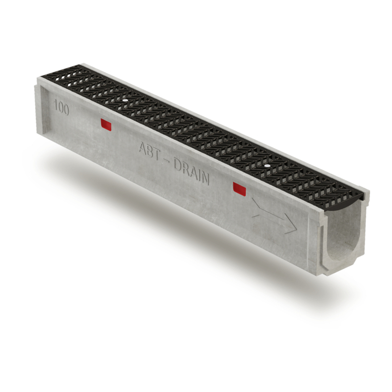
Abt
Abt POLYDRAIN PDX-Pin Lock installation guide
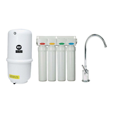
Watts
Watts WQC4 RO SERIES Installation, operation and maintenance manual

Spectra Watermakers
Spectra Watermakers Ventura 150T MPC Installation and operating manual

Rototec
Rototec DEPURO ONE Maintenance manual

Zip
Zip HydroTap G4 BCS160/175 Installation and operating instructions
