Albinus
Water Pressure System WPS 4.0 12V / 24V,
WPS 5.3 12V / 24V
Albinus 500-series 5-chamber diaphragm Water Pressure System pumps for providing
pressurized water on demand! Our WPS pumps supply continuous, pulsation-free,
pressurized ow of both hot and cold water to faucets, shower heads and more.
• Easy to install
• Integrated extra heavy duty sealed pressure switch
• Smooth & Pulsation-free ow
• Quiet operation
• Serves up to 5 outlets (WPS 4.0) or 6 outlets (WPS 5.3)
• Self-priming up to 2.5 m (8.2 ft)
• Quick disconnect ports
• Connection with ½" and ¾" hose
• Click-on 40 µm mesh strainer included
• Manufactured according to CE standard; EN55014-1, ISO 88461 & ISO10133.
Under approval
part no. 02-02-006 Water Pressure Pump WPS 4.0 15 L/min (4.0 GPM) 12V 10A ½" and ¾" hose
part no. 02-02-007 Water Pressure Pump WPS 4.0 15 L/min (4.0 GPM) 24V 5A ½" and ¾" hose
part no. 02-02-008 Water Pressure Pump WPS 5.3 20 L/min (5.3 GPM) 12V 15A ½" and ¾" hose
part no. 02-02-009 Water Pressure Pump WPS 5.3 20 L/min (5.3 GPM) 24V 8A ½" and ¾" hose
Operation:
When water is tapped from the system, for example from a faucet or a shower head,
the pressure in the water supply system will drop. At the factory-set cut-in pressure of
1.7bar (25psi) the WPS pump's integrated pressure switch will automatically turn on
the pump to boost the water system pressure, providing continuous, pulsation free
ow. The WPS pump automatically turns o when the pre-set cut-o pressure of 2.8 bar
(40psi) is reached.
A check valve on the outlet maintains the pressure in the water system between uses
so that pressurized water is always available. For the optimum Water Pressure System:
install the WPS pump together with Albinus Accumulator Tank 02-66-022.
Technical Specications:
Body: Nylon/Polypropylene
Valve housing: Polypropylene/Polyamide
Valves: Santoprene/EPDM
Diaphragm: Santoprene
Connection: ½" and ¾" hose
Inlet strainer: 40µm mesh, included
Max. liquid temperature: Max +50°C/+120°F
Fasteners: Stainless steel
Max. suction lift: WPS 4.0 – 2m/6.5ft
WPS 5.3 – 2.5m/8.2ft
Cut in pressure: 1.7bar (25psi)
Cut-o pressure: 2.8bar (40psi)
Duty cycle: Intermittent, max 20 min
Motor: WPS 4.0 – 100W
WPS 5.3 – 150W
12/24V DC with built in thermal protection
Manufactured according to CE standard;
EN55014-1, ISO 88461 & ISO10133. Under approval
Installation:
The pump must be mounted in a dry, ventilated location and must not be submerged.
Selection of a cool ventilated location will generally extend pump motor life. Mount the
pump horizontally with space for maintenance. If you choose to mount the pump
vertically, mount with the motor pointing upwards.
Mark screw positions and drill pilot holes (see drilling template). Mount the pump
using stainless steel screws and with the accompanying washers; do not over tighten
the screws so that the vibration dampening of the composite base is not compromised.
For connecting to the water piping, it is recommended to use reinforced, high pressure
exible tubing. If rigid piping is used for the connection, a length of exible tubing
(225mm/9 inches minimum) should be installed between the pump and the rigid
pipe. This will stop noise and/or damage caused by any vibrations transmitted to rigid
pipe. Use stainless steel hose clamps to secure tubing to the quick disconnect ttings
and any other hose barbs present in the system.
NOTE:
The included strainer must be installed at the pump intake, to prevent debris from
entering pump, causing damage and interfering with the proper functioning of valves.
Electrical connections:
The pump must be installed according to SS-EN ISO 10133 (Small craft – Electrical
system – Extra low voltage DC installation for continuous current). Note: The fuse
must be ignition protected. The motor is equipped with built-in thermal protection to
prevent the motor from overheating. The protection is automatically reset when the
motor has cooled. If the pump is connected with a separate earth lead, connect it to
metallic part of the motor. See the wiring diagram for correct installation. In keeping
with standard electrical nomenclature, the Negative wire must be black and the Earth
lead (if used) should be yellow/green. Choose wire size in accordance with total wire
length.
Red +
Fuse
Earth
Inlet
Battery
12 V / 24 V
Discharge
Flexible
hose
Accumulator
Tank
Flexible
hose
Connect black wire to negative (–) terminal of battery. The red wire should run to the
positive (+) terminal of battery, with a properly sized fuse must be placed between the
battery's positive terminal (+) and the pump. Other electrical devices, such as switches
or circuit breaker, must be installed between the pump and the positive (+) lead on
the battery (on the red wire). Use proper wire size as determined by wire table below.
Wiring must comply with applicable electrical standards.
All wire connections must be sealed with a marine sealant. Note!: Before the
installation of electrical control systems, check that the capacity of the equipment to
be used is of sucient rating to accept the amperage draw of the motor. Low voltage
will cause the motor to overheat.
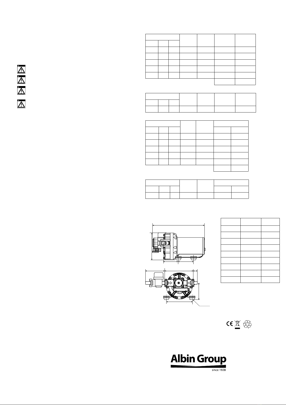
WPS 4.0
Wire size
(based on 3%
voltage drop)
Max wire length (total
distance from the battery to
the pump and back to the
battery)
12V 24V
2.5mm² (14ga) 7 m (23') 30 m (98.4')
4 mm² (12ga) 11 m (36') 49 m (161')
6mm² (10ga) 16 m (52.5') 73 m (240')
10mm² (6ga) 27 m (88.6') 122 m (400')
WPS 5.3
Wire size
(based on 3%
voltage drop)
Max wire length (total
distance from the battery to
the pump and back to the
battery)
12V 24V
2.5mm² (14ga) 5 m (16') 22 m (72.2')
4 mm² (12ga) 8 m (26') 34 m (111')
6mm² (10ga) 12 m (39.4') 52 m (170')
10mm² (6ga) 20 m (65.6') 86 m (282.2')
16mm² (4ga) 31 m (102') 138 m (452.8')
Start-up procedure
After installing the pump, initiate the water system as follows:
1. Fill the water tank
2. Open one tap fully
3. Turn on the pump
4. Close the tap once the water begins owing
5. Open each additional tap until all air has been purged from system
6. The pump will shut o after taps are closed and pressure builds to the pre-set cut-
o pressure of the integrated pressure switch
Maintenance:
Periodically sanitize the system as follows:
1. Fill the water tank with a solution of household bleach and potable water – 1 ml
(.03oz.) bleach/1 L (33 oz.) water.
2. Open all faucets and let run until owing water smells of bleach
3. Close all faucets.
4. Drain the bleach/solution from the tank.
5. Rell the water tank with potable water.
6. Open all of the faucets and let the water run until bleach has been emptied from
the system.
Winterizing
If water is not drained from the system at freezing ambient temperatures, damage will
occur to the water pipes and in the pump. To prevent this follow these instructions:
1. Drain the water storage tank.
2. Open all taps.
3. Run the pump until the remaining water is expelled from the system.
4. Disconnect the inlet and outlet tubing.
5. Run the pump briey to conrm that all water has been expelled.
6. Switch o the electrical power to the pump.
7. Keep the taps open and the pump ttings disconnected until temperatures are
above freezing again.
8. To re-instate the pump, follow the directions under "Start up procedure"
Never start a frozen pump. Even when drained it might contain a small amount of ice
that will lock the pump.
wiring diagram