Watt Drive V2500 Series User manual

FREQUENCY INVERTER
Series V2500
MANUAL

WATT DRIVE worldwide
WATT DRIVE ANTRIEBSTECHNIK GMBH
A-2753 Markt Piesting
Wöllersdorferstraße 68
Austria, EUROPE
Tel.: +43 / 2633 / 404-0
Fax: +43 / 2633 / 404-220
Web: www.wattdrive.com
BA.FBE.UR.024.001.07.03
V2500 Kurzanleitung dt/engl.
Watt Drive operates a policy of continuous development. Therefore, we reserve the right to make
changes and improvements to any of our products described in this manual without prior notice. Any
changes, improvements and typing errors justify no claims for compensation.
WATT DRIVE NORD GmbH
Eickelstraße 4
D-59759 Arnsberg
Germany, EUROPE
Tel.: +49 / 2932 / 96 81-0
Fax: +49 / 2932 / 96 81-81
Web: www.wattdrive.de
WATT DRIVE SÜD GmbH
Walkenmühleweg 49
D-72379 Hechingen
Germany, EUROPE
Tel.: +49 / 7471 / 9865-0
Fax: +49 / 7471 / 9865-29
Web: www.wattdrive-sued.de
WATT EURO-DRIVE (Far East) Pte Ltd
67B, Joo Koon Circle
Singapore 629082
Tel.: +65 / 686 22 220
Fax: +65 / 686 23 330
Web: www.wattdrive.com
WATT EURO-DRIVE (Malaysia) Sdn Bhd
No. 17 Jalan Bulan U5/8
Bandar Pinggiran Subang 2
40150 Shah Alam
Selangor Darul Ehsan
Malaysia
Tel.: +603 / 785 91626, 785 91613
Fax: +603 / 785 91623
Web: www.wattdrive.com

0
0-1
PREFACE
Thank you for choosing WATT DRIVE Antriebstechnik GmbH performance V2500 Series.
V2500 Series are manufactured by adopting high-quality components, material and
incorporating the latest microprocessor technology available.
! Getting Started
This manual will be helpful in the installation, parameter setting, troubleshooting, and
daily maintenance of the AC motor drives. To guarantee safe operation of the
equipment, read the following safety guidelines before connecting power to the AC
drives. Keep this operating manual handy and distribute to all users for reference.
!DANGER!
This message indicates a situation which may lead to serious injury or
even death if the instruction is not observed.
!CAUTION!
This message indicates a situation which may lead to minor or moderate
injury, or damage of product.
!HAZARDOUS HIGH VOLTAGE!
Motor control equipment or electronic controllers are connected to hazardous
line voltages.
When servicing drives and electronic controllers there might exist exposed
components with cases or protrusions at or above line potential.
Extreme care should be taken to protect against shock.
For these reasons, the following safety guidelines should be observed:
Stand on an insulating pad and make it a habit to use only one hand when
checking components. Disconnect power before checking controllers or
performing maintenance. Be sure that equipment is grounded properly. Wear
safety glasses whenever working on an electronic controller or rotating
electrical equipment.
!DANGER!
This equipment should be installed, adjusted and serviced only by qualified
electrical maintenace personel familiar with the construction and operation of the
equipment and the hazards involved. Failure to observe this precaution could result
in bodily injury.
!CAUTION!
These instructions should be read and clearly understood before working on V2500
series equipment.
!DANGER!
The user is responsible that all driven machinery, drive train mechanism not
supplied by WATT Drive Antriebstechnik and process line material are capable of safe
operation at an applied frequency of 150% of the maximum selected frequency range
to the AC motor. Failure to do so can result in destruction of equipment and injury to
personnel should a single point failure occur.
!DANGER!
HAZARD OF ELECTRICAL SHOCK. DISCONNECT INCOMING POWER BEFORE
WORKING ON THIS CONTROL.
Do not connect or disconnect wires and connectors while power is applied to
the circuit. Maintenance must be performed by qualified technicians.

CHAPTER 0: PREFACE
0-2
!DANGER!
A charge may still remain in the DC-link capacitor with hazardous voltages even if
the power has been turned off. To avoid personal injury, please ensure that power
has turned off before operating AC drive and wait ten minutes for capacitors to
discharge to safe voltage levels.
!CAUTION!
Proper grounds, disconnecting devices (e.g. fuses) and other safety devices and
their location are the responsibility of the user and are not provided by WATT
DRIVE Antriebstechnik GmbH.
!CAUTION!
Rotating shafts and electrical potentials above ground level can be hazardous.
Therefore it is strongly recommended that all electrical work conform to the national
electrical codes and local regulations. Installation, maintenance and alignment
should be performed by qualified personnel only.
Factory recommended test procedures included in this instruction manual should be
followed. Always disconnect electrical power before working on the unit.
!DANGER!
a) Any motor used must be of suitable rating.
b) Motors may have hazardous moving parts so that suitable protection must be
provided in order to avoid injury.
!CAUTION!
Alarm connections may have hazardous live voltages even when the inverter is
disconnected. In case of removing the front cover for maintenance or inspection,
confirm that incoming power for alarm connections is surely disconnected.
!CAUTION!
There are highly sensitive MOS components on the printed circuit boards. These
components are especially sensitive to static electricity. To avoid damage to these
components, do not touch these components or the circuit boards with metal
objects or your bare hands.
!CAUTION!
Ground the V2500 using the ground terminal. The grounding method must comply
with the laws of the country where the AC drive is to be installed. Refer to Basic
Wiring Diagram (Chapter 3).
!CAUTION!
The final enclosures of the AC drive must comply with EN50178. (Live parts shall be
arranged in enclosures or located behind barriers that meet at least the
requirements of the Protective Type IP20 Main terminals or other hazardous
terminals for any interconnection (terminals for connecting the motor, contact
breaker, filter etc.) must be inaccessible after installation.. The top surface of the
enclosures or barrier that is easily accessible shall meet at least the requirements of
the Protective Type IP40). (V2500 series corresponds with this regulation.)
!CAUTION!
The rated voltage of power system that is installed on AC drive must be equal to or
less than 240 Volts (400 / 460V model is 480 Volts) and the current must be equal
to or less than 5000A RMS.
0
0-3
!DANGER!
The AC drive may be destroyed beyond repair if incorrect cables are connected to
the input/output terminals. Never connect the AC drive output terminals U/T1,
V/T2, and W/T3 directly to the AC main circuit power supply.
!CAUTION!
Turn power on only when the DC-link capacitors are fully discharged.
CAUTION!
Heat sink may heat up over 70°C, during the operation. Do not touch the heat sink.
All of the above instructions, together with any other requirements,
recommendations, and safety messages highlighted in this manual must be strictly
complied with.


TABLE OF CONTENTS
• Chapter 1 – receiving and inspection
• Chapter 2 – storage and installation
• Chapter 3 – wiring
• Chapter 4 – digital keypad operation
• Chapter 5 – parameters
• Chapter 6 – maintenance and inspections
• Chapter 7 – troubleshooting and fault information
• Chapter 8 – summary of parameter settings
• Appendix A – specifications
• Appendix B – accessories
• Appendix C – dimensions

CHAPTER 1: RECEIVING AND INSPECTION
1-1
CHAPTER 1 RECEIVING AND INSPECTION
This V2500 AC drive has gone through rigorous quality control tests at the factory before
shipment. After receiving the AC drive, please check for the following:
Receiving
! Check to make sure that the package includes an AC drive, the User Manual, dust
covers and rubber bushings.
! Inspect the unit to insure it was not damaged during shipment.
! Make sure that the part number indicated on the nameplate corresponds with the
part number of your order.
1.1 Nameplate Information: Example for 0.75 kW/1HP 1/3-phase 230V AC drive
1.2 Model Explanation:
1.3 Series Number Explanation:
If there is any nameplate information not
corresponding to your purchase order or any
problem, please contact your distributor.
Inverter Model
Input Specification: phases, voltage, frequency,
current
Output Specification: phases, voltage range,
rated current andpower
Output Frequency Range
Serial Number and Bar Code

2
2-1
CHAPTER 2 STORAGE AND INSTALLATION
2.1 Storage
The AC drive should be kept in the shipping carton before installation. In order to retain the
warranty coverage, the AC drive should be stored properly when it is not to be used for an
extended period of time.
Ambient Conditions:
Operation Air Temperature: -10oC to +40oC
+50oC without dust cover.
Atmosphere pressure: 86 to 106 kPa (0,86 to 1,06 bar)
Installation Site Altitude: below 1.000m
Power de-rating at high Site Altitude:
above 1.000m -1% per 100m (max. 3.000m)
Vibration: Maximum 9.80 m/s2(1G) at less than 20Hz
Maximum 5.88 m/s2(0.6G) at 20Hz to 50Hz
Storage Temperature: -20oC to +60oC
Relative Humidity: Less than 90%, no condensation allowed
Atmosphere pressure: 86 to 106 kPa (0,86 to 1,06 bar)
Transportation Temperature: -20oC to +60oC
Relative Humidity: Less than 90%, no condensation allowed
Atmosphere pressure: 86 to 106 kPa (0,86 to 1,06 bar)
Vibration: Maximum 9.80 m/s2(1G) at less than 20Hz, Maximum
5.88 m/s2(0.6G) at 20Hz to 50Hz
Pollution Degree 2: good for a factory type environment.
CHAPTER 2: STORAGE AND INSTALLATION
2-2
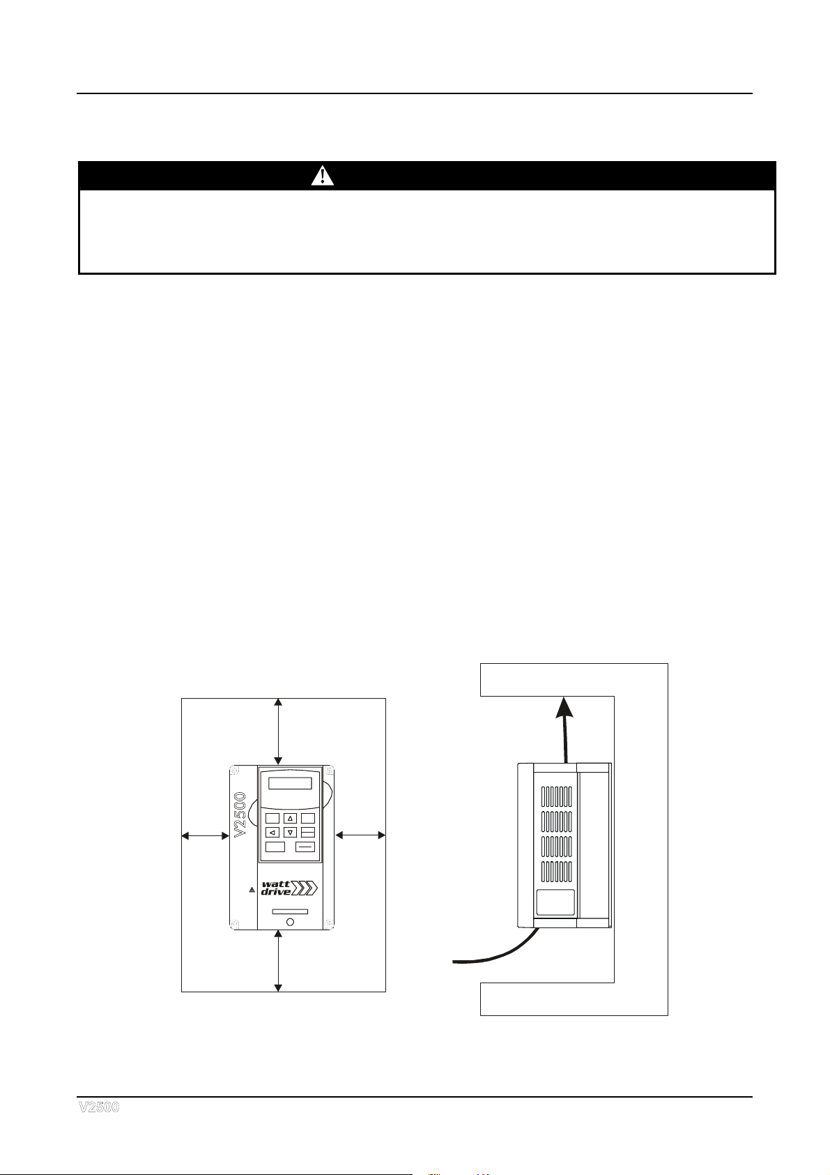
2.2 Installation:
CAUTION
The control, power supply and motor leads must be laid separately. They must not be
fed through the same cable conduit / trunking.
High voltage insulation test equipment must not be used on cables connected to the
drive.
Improper installation of the AC drive will greatly reduce its life. Be sure to observe the
following precautions when selecting a mounting location.
Failure to observe these precautions may void the warranty!
! Do not mount the AC drive near heat-radiating elements or in direct sunlight.
! Do not install the AC drive in a place subjected to high temperature, high humidity,
excessive vibration, corrosive gases or liquids, or airborne dust or metallic particles.
! Mount the AC drive vertically and do not restrict the air flow to the heat sink fins.
! The AC drive generates heat. Allow sufficient space around the unit for heat
dissipation.
ACHTU NG
HOCHSPANNUNG:VOR
DEM ÖFF NE N DES
UM RI C HTE RS MIN DE STE N S
5 MINUTENWARTEN.
BETRIEBSANLEITUNG
BEACHTEN
WARNING- HIGH VOLTAGE:
WAI T AT LEAS T 5 MIN UTES
BEFOREOPENING.
FOL LO W US ER M ANU A L
ECO -li ne
OPTI-line
JOG MODE
PROG
DATA
STOP
RESET
RUN
V2500-0220TDA1
F
H
U
RUN STOP JOG FWD REV
120mm
4.72inch
50mm
1.97inch
A
ir Flow
50mm
1.97inch
120mm
4.72inch

3
3-1
CHAPTER 3 WIRING
DANGER
Hazardous Voltage
Before accessing the AC drive:
Disconnect all power to the AC drive.
Wait five minutes for DC bus capacitors discharge.
Any electrical or mechanical modification to this equipment without prior written
consent of WATT Drive Antriebstechnik GmbH will void all warranties and may
result in a safety hazard in addition to voiding the UL listing or CE conformity.
Short Circuit Withstand:
The rated voltage must be equal to or less than 240V (400/460V model is 480Volts) and
the current must be equal to or less than 5000A RMS. (the model of 30 kW or above is
10000A RMS)
General Wiring Information
For installation in compliance with CE standards you must follow the instructions provided
in the section “Notes on EMC” in this chapter.
All V2500 AC drives except Underwriters Laboratories, Inc. (UL) and Canadian
Underwriters Laboratories (CUL) listed, and therefore comply with the requirements of
the National Electrical Code (NEC) and the Canadian Electrical Code (CEC) and CE
conformity.
Installation intended to meet the UL and cUL requirements must follow the instructions
provided in “Wiring Notes” as a minimum standard. Follow all local codes that exceed UL
and cUL requirements. Refer to the technical data label affixed to the AC drive and the
motor nameplate for electrical data.
The "Line Fuse Specification" in Appendix B, lists the recommended fuse part number for
each V2500 part number. These fuses (or equivalent) must be used on all installations
where compliance with U.L. standards is a required.

CHAPTER 3: WIRING
3-2
NOTES ON EMC (ELECTRO MAGNETICAL COMPATIBILITY)
WARNING
This equipment should be installed, adjusted and serviced by qualified
personnel familiar with construction and operation of the equipment and the
hazards involved. Failure to observe this precaution could result in bodily
injury.
When using V2500 series inverters in EU countries, the EMC directive 89/336/EEC
must be observed. To satisfy the EMC directive and to comply with the standard, the
following provisions should be obeyed:
A)Environmental conditions for the inverter:
• Ambient temperature: -10°C to 40°C.
• Relative Humidity: 20% to 90% (no dew condensation)
• Vibrations: max. 5,9m/s2(0.6 g) at 10–55Hz.
• Location: 1000 meter or less altitude, indoors (no corrosive gas or dust).
B) The power supply to the V2500 inverter must conform to the conditions stated
below. If one of the conditions mentioned is not satisfied then an appropriate
V2500 AC reactor will have to be installed.
• Voltage fluctuation +/-10% or less
• Voltage unbalance +/-3% or less
• Frequency variation +/-4% or less
C) Wiring
• Shielded wiring (screened cable) is required for motor wiring, and total
length has to be kept to less than 50m. When using motor cables longer
than 50m, V2500 motor filters should be installed. Directions for installing
filters can be found in the V2500 installation manual.
• Seperate the mains circuit wiring from the wiring used for signals or process
circuit. Please refer to the V2500 installation manual.
D) Installation
• For V2500 series inverters, the filters described hereafter have to be used
and the installation notes have to be observed.
If installed according to the following directions, the frequency inverters comply
with the following standards:
Emmissions: EN 61800-3 (EN 55011 group 1, class B)
Immunity: EN 61800-3, (industrial environments)
For the best possible damping of interference, special line filters have been
developed which guarantee you easy assembly and installation along with the
necessary electrical reliability. However, effective EMC is only ensured if the
suitable filter is selected for the particular drive and installed in accordance with
these EMC recommendations.
The amount of line-conducted interference also increases as motor cable length
increases. Adherence to the interference limits for line-conducted interference is
guaranteed on following way:
• If maximum motor cable length is 35 m (200/240V-inverters) and 15 or 20 m
(400/460V inverters) – details see Appendix A: Class „B“
• If maximum motor cable length is between 25 and 80 m (depending on
inverter size) – details see Appendix A: Class „A“

3
3-3
Observe the following provisions for an electromagnetically compatible setup of
your drive system:
1.As user you must ensure that the HF impedance between frequency inverter,
filter and ground is as small as possible.
• Take care it that the connections are metallic and have the largest possible
areas (zink-plated mounting plates)
2.Conductor loops act like antennas, especially when they encompass large
areas. Consequently:
• Avoid unnecessary conductor loops
• Avoid parallel arrangement of „clean“ and interference-prone conductors
3.Lay the motor cable and all analog and digital control lines shielded.
• You should allow the effective shield area of these lines to remain as large as
possible; i.e., do not move the shield further away than absolutely
necessary.
• With compact systems, if for example the frequency inverter is
communicating with the steering unit, in the same control cabinet connected
at the same PE-potential, the screen of control lines should be put on, on
both sides with PE. With branch systems, if for example the communicating
steering unit is not in the same control cabinet and there is a distance
between the systems, we recommend to put on the screen of control lines
only on the side of the frequency inverter. If it is possible, direct in the cable
entry section of the steering unit. The screen of Motor cabels always must be
put on, on both sides with PE.
• The large area contact between shield and PE-potential you can realise with
a metal PG screw connection or a metallic mounting clip.
• Use only copper mesh cable (CY) with 85% coverage
• The shielding should not be interrupted at any point in the cable. If the use of
reactors, contactors, terminals or safety switches in the motor output is
necessary, the unshielded section should be kept as small as possible.
• Some motors have a rubber gasket between terminal box and motor housing.
Very often, the terminal boxes, and particularly the threads for the metal PG
screw connections, are painted. Make sure there is always a good metallic
connection between the shielding of the motor cable, the metal PG screw
connection, the terminal box and the motor housing, and carefully remove
this paint if necessary.
4.Very frequently, interference is coupled in through installation cables. This
influence you can minimize:
• Lay interfering cables separately, a minimum of 0.25 m from cables
susceptible to interference.
• A particularly critical point is laying cables parallel over larger distances. If
two cables intersect, the interference is smallest if they intersect at an angle
of 90°. Cables susceptible to interference should therefore only intersect
motor cables, intermediate circuit cables, or the wiring of a rheostat at right
angles and never be laid parallel to them over larger distances.
5.The distance between an interference source and an interference sink
(interference-threatened device) essentially determines the effects of the
emitted interference on the interference sink.
• You should use only interference-free devices and maintain a minimum
distance of 0.25 m from the drive.
CHAPTER 3: WIRING
3-4
6.Safety measures
• Ensure that the protective conductor terminal (PE) of the filter is properly
connected with the protective conductor terminal of the frequency inverter.
An HF ground connection via metal contact between the housings of the
filter and the frequency inverter, or solely via cable shield, is not permitted as
protective conductor connection. The filter must be solidly and permanently
connected with the ground potential so as to preclude the danger of electric
shock upon touching the filter if a fault occurs. You can achieve this by
connecting it with a grounding conductor of at least 10 mm² or connecting a
second grounding conductor, connected with a separate grounding terminal,
parallel to the protective conductor (the cross section of each single
protective conductor terminal must be designed for the required nominal
load).
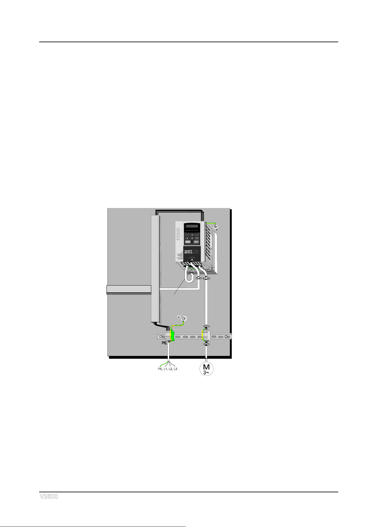
Cabinet installation of V2500 foot print filter:
PE-connection
3
3-5
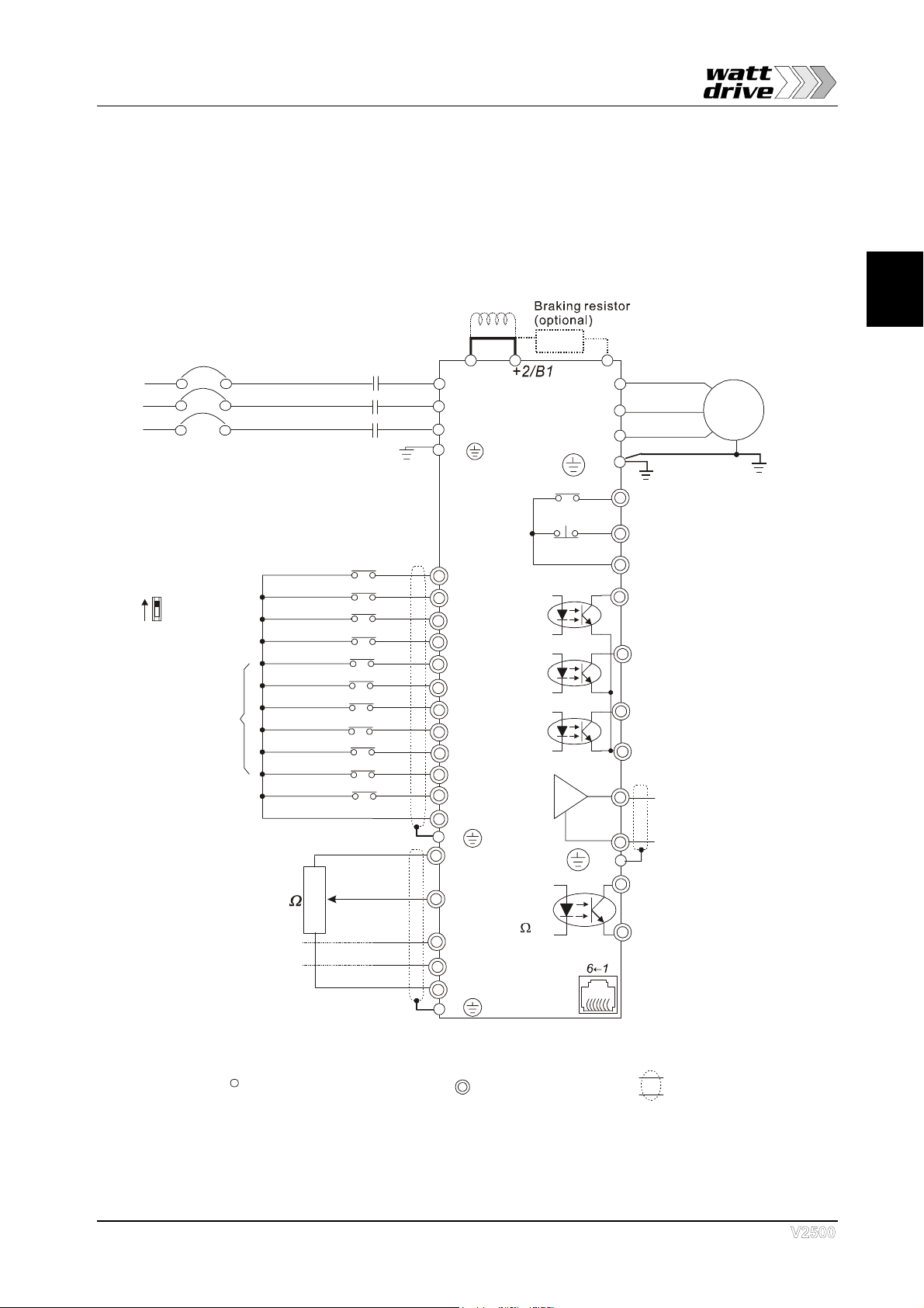
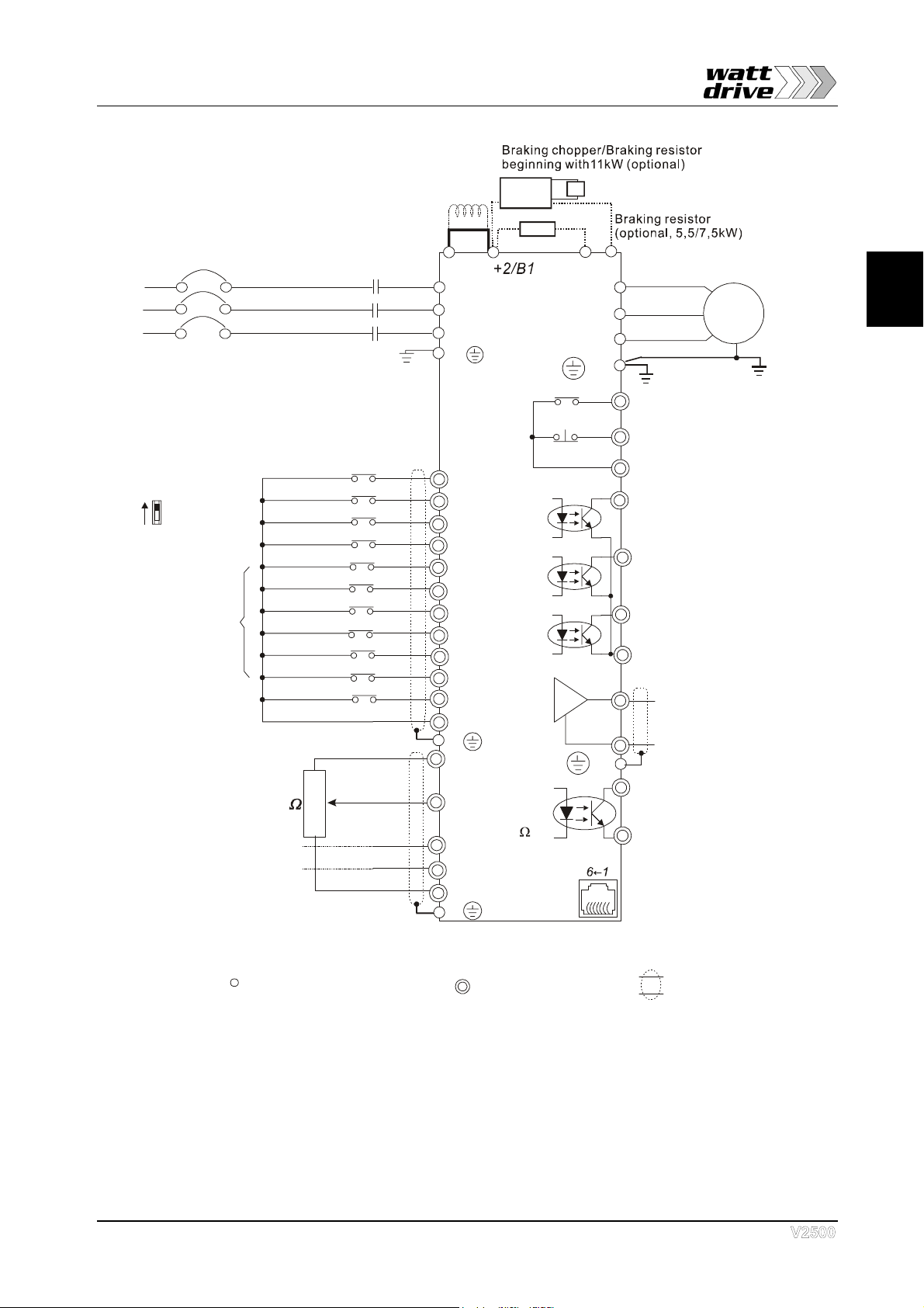
3.1 Basic Wiring Diagram
Users must connect wires according to the following circuit diagram shown below. Do not
plug a Modem or telephone line to the RS-485 communication port, permanent damage
may result. Terminals 1 & 2 are the power sources for the optional copy keypad and
should not be used while using RS-485 communication.
AVI
ACI
AUI
ASC
B2
4~20mA
-10~+10V
5K
3
2
1
Fi
g
ure 1 for models of V2500 Series
1~0.75/1.5; 3~0.75-2.2kW
Jumper
Master Frequency
0 to 10V 47K
Analog Signal Common
DC choke
(optional)
E
Main circuit (power) terminals Control circuit terminals Shielded leads & Cable
FWD
REV
JOG
EF
DI1
DI2
DI3
DI4
DI6
TRG
DI5
DIC
+24V
Sw1
Sink
Source
Factory Default:
SINK Mode
FWD/STOP
REV/STOP
JOG
E.F.
Multi-step 1
Multi-step 2
Multi-step 3
Multi-step 4
RESET
Counter
Digital Signal Common
Factory
default
* Don't apply the mains voltage directly
to above terminals.
E
Please refer to Figure 4
for wiring of SINK
mode and SOURCE
mode.
R(L1)
S(L2)
T(L3)
Fuse/NFB(None Fuse Breaker)
+1
R(L1)
S(L2)
T(L3)
E
Analog Multi-function Output
Te r m i n a l
Factory default: Analog freq.
/ current meter
0~10VDC/2mA
U(T1)
V(T2)
W(T3)
IM
3~
DO1
DO2
DO3
AFO
ASC
RA
RB
RC
DOC
RS-485
Motor
Factory default:
indicates during operation
48V50mA
Factory default:
Freq. Setting Indication
Factory default:
Low-voltage Indication
Multi-function
Photocoulper Output
Analog Signal common
Serial interface
1: EV 2: GND
5:NC
6: for communication
3: SG-
4: SG+
DFO
DIC
Digital Frequency Output
Te r m in a l
Factory default: 1:1
Duty=50%
Digital Signal Common
48V50mA
48V50mA
E
E
Please refer to “Control
Terminal Explanation”
see page 3-10
1 /2 Accel/Decel
st nd
+10V/20mA

CHAPTER 3: WIRING
3-6
1 /2 Accel/Decel
st nd
AVI
ACI
AUI
ASC
4~20mA
-10~+10V
5K
3
2
1
Fi
g
ure 2 for models of V2500 Series
1~2.2; 3~4.0kW
Master Frequency
0 to 10V 47K
Analog Signal Common
E
Main circuit (power) terminals Control circuit terminals Shielded leads & Cable
FWD
REV
JOG
EF
DI1
DI2
DI3
DI4
DI6
TRG
DI5
DIC
+24V
Sw1
Sink
Source
Factory Default:
SINK Mode
FWD/STOP
REV/STOP
JOG
E.F.
Multi-step 1
Multi-step 2
Multi-step 3
Multi-step 4
RESET
Counter
Digital Signal Common
Factory
default
* Don't apply the mains voltage directly
to above terminals.
E
Please refer to Figure 4
for wiring of SINK
mode and SOURCE
mode.
R(L1)
S(L2)
T(L3)
Fuse/NFB(None Fuse Breaker)
R(L1)
S(L2)
T(L3)
E
Analog Multi-function Output
Te r m i n a l
Factory default: Analog freq.
/ current meter
0~10VDC/2mA
U(T1)
V(T2)
W(T3)
IM
3~
DO1
DO2
DO3
AFO
ASC
RA
RB
RC
DOC
RS-485
Motor
Factory default:
indicates during operation
48V50mA
Factory default:
Freq. Setting Indication
Factory default:
Low-voltage Indication
Multi-function
Photocoulper Output
Analog Signal common
Serial interface
1: EV 2: GND
5:NC(EV2 for 300T~750T)
6: for communication
3: SG-
4: SG+
DFO
DIC
Digital Frequency Output
Te r m in a l
Factory default: 1:1
Duty=50%
Digital Signal Common
48V50mA
48V50mA
E
E
* For the single phase application, the AC input line can
be connected to any two of the three input terminals R,S,T
* Three phase input power may apply to single phase drives.
Jumper
DC chock
(optional)
Please refer to “Control
Terminal Explanation”
see page 3-10
+10V/20mA
+1 B2
BR
3
3-7
1 /2 Accel/Decel
st nd
AVI
ACI
AUI
ASC
4~20mA
-10~+10V
5K
3
2
1
Fi
g
ure 3 for models of V2500 Series
5.5kW - 75kW
Master Frequency
0 to 10V 47K
Analog Signal Common
E
Main circuit (power) terminals Control circuit terminals Shielded leads & Cable
FWD
REV
JOG
EF
DI1
DI2
DI3
DI4
DI6
TRG
DI5
DIC
+24V
Sw1
Sink
Source
Factory Default:
SINK Mode
FWD/STOP
REV/STOP
JOG
E.F.
Multi-step 1
Multi-step 2
Multi-step 3
Multi-step 4
RESET
Counter
Digital Signal Common
Factory
default
* Don't apply the mains voltage directly
to above terminals.
E
Please refer to Figure 4
for wiring of SINK
mode and SOURCE
mode.
R(L1)
S(L2)
T(L3)
Fuse/NFB(None Fuse Breaker)
R(L1)
S(L2)
T(L3)
E
Analog Multi-function Output
Te r m i n a l
Factory default: Analog freq.
/ current meter
0~10VDC/2mA
U(T1)
V(T2)
W(T3)
IM
3~
DO1
DO2
DO3
AFO
ASC
RA
RB
RC
DOC
RS-485
Motor
Factory default:
indicates during operation
48V50mA
Factory default:
Freq. Setting Indication
Factory default:
Low-voltage Indication
Multi-function
Photocoulper Output
Analog Signal common
Serial interface
1: EV 2: GND
5:NC
6: for communication
3: SG-
4: SG+
DFO
DIC
Digital Frequency Output
Te r m in a l
Factory default: 1:1
Duty=50%
Digital Signal Common
48V50mA
48V50mA
E
E
Jumper
DC chock
(optional)
Please refer to “Control
Terminal Explanation”
see page 3-10
+10V/20mA
+1 B2
VFDB
BR
BR

CHAPTER 3: WIRING
3-8
Figure 4 for all models V2500
SINK Mode and SOURCE Mode
Sw1
Sink
Source
1 /2 Accel/Decel
st nd
1 /2 Accel/Decel
st nd
DIC
DIC

3
3-9
3.2 Terminal Explanations
Terminal Symbol Explanation of Terminal Function
R/L1, S/L2, T/L3 AC line input terminals
U/T1, V/T2, W/T3 AC drive output terminals motor connections
+1,+2 Connections for DC Link Reactor (optional)
+2/B1-B2 Connections for Braking Resistor (optional)
+2 - -(minus sign)
+2/B1- -(minus sign) Connections for External Braking Unit (V2500 series)
Earth Ground
3.3 Control Terminals Explanations
Terminal Symbols Terminal Functions Factory Settings
FWD Forward-Stop command
REV Reverse-Stop command
JOG Jog command
EF External fault
TRG External counter input
DI1 Multi-function Input 1
DI2 Multi-function Input 2
DI3 Multi-function Input 3
DI4 Multi-function Input 4
DI5 Multi-function Input 5
DI6 Multi-function Input 6
Refer to Pr.04-04 to Pr.04-09
Multi-function Input Terminals
DFO Digital Frequency Meter
(Open Collector Output)
Factory setting 1:1
(Maximum 48VDC, 50mA)
+24V DC Voltage Source (+24V, 20mA), used for source
mode.
DIC Digital Signal Common Used as common for digital
inputs and used for sink mode.

CHAPTER 3: WIRING
3-10
Terminal Symbols Terminal Functions Factory Settings
RA Multi-function Relay output
(N.O.) a
RB Multi-function Relay output
(N.C.) b
RC Multi-function Relay common
Resistor Load
5A(N.O.)/3A(N.C.) 240VAC
5A(N.O.)/3A(N.C.) 24VDC
Inductive Load
1.5A(N.O.)/0.5A(N.C.) 240VAC
1.5A(N.O.)/0.5A(N.C.) 24VDC
Refer to Pr.03-01 to Pr.03-03
DO1 Multi-function output 1
(Photocoupler)
DO2 Multi-function output 2
(Photocoupler)
DO3 Multi-function output 3
(Photocoupler)
Maximum 48VDC, 50mA
Refer to Pr.03-01 to Pr.03-03
DOC Multi-function output common Maximum 48VDC, 50mA
+10V Potentiometer output
power source +10V 20mA
AVI Analog voltage Input 0 to +10V
ACI Analog current Input 4 to 20mA
AUI Auxiliary analog voltage input -10 to +10V
AFO Analog output meter 0 to 10V, 2mA
ASC Analog control signal
(common)
* Control signal wiring size: 18 AWG (0.75 mm2).
This manual suits for next models
18
Table of contents
Popular DC Drive manuals by other brands


Siemens
Siemens Micromaster Eco Reference manual

Danfoss
Danfoss VLT FC 103 Design guide

Danfoss
Danfoss VLT FC 103 operating guide

American Control Electronics
American Control Electronics Minarik MDVF03-D230-PCM quick start guide

Leadshine Technology
Leadshine Technology M415B user manual

Newport
Newport New Focus 8712 user manual