Watts BT-OS02-RF User manual

PPLIMW15086Ae
52mm
80mm
“ RF init ”
Wireless outside temperature probe
1. INSTRUCTION
- The probe must be placed on the wall with the enclosed screws, or otherwise if the support is not
appropriated.
Once fixed on the wall, don’t forget to put the rubber caps provided to ensure the tightness of the box
against dripping water.
- the probe must be preferably placed on a north or north/west wall sheltered for weather and away from
parasites of heat sources such suction, exhaust air of the building, …
2. INITIALISATION RF
- Switch on the RF outdoor probe
- In the central unit, go in the installer menu / Radio pairing and select “External Probe” device. Press on
Radio Pairing icon.
The bicolor LED blinks and informs you about the status of the transmission between the probe and the
central unit:
- Red : communication problem, the synchronization is not successful, you must restart the
initialization process by moving the probe (see note 1)
- Green : success, the synchronization is successful, you can now fix permanently the probe.
After flashing red or green LED turns off, the synchronization is complete.
Note 1 : Avoid metal surfaces between the probe and the Central that can disturb radio communications. It
is then recommended to move the probe away from the obstacle.
3. TECHNICAL CARACTERISTICS
Operating temperature
- 50°C to 65°C
Power supply
Operating life
1 Lithium AA battery (LR06) 2600mAh
10 years
Radio Frequency
868.00 MHz <10mW.
Range of approximately 180m in open space.
Range of approximately 30m in residential environment
Homologations
EN 300220-1, -2 / EN 301489-1, -3
R&TTE
Protection Marking
IP 65
Status LED
Blinking green (flash 10sec)
Blinking reg (2 flash / ~ 10min)
RF initialization
Low batteries
4. BATTERY REPLACEMENT
- If the status led of your RF probe blinks red during a transmission (every 10 minutes approximatively), it
will be necessary to replace the battery.
- Switch off your RF probe
- Take off the used battery (Do not throw your battery in the trash, recycle as it should be)
- Put the new battery
- Switch ON your probe (pointing up), the led status blinks green.
- Wait 10 seconds to see if the communication is correct: the green LED blinks
- Close the box
52mm
80mm
80mm
Note :
Before permanently attaching the probe,
redo the initialization step with the Central to
valid the choice of location.
Push button
Status LED
Battery
“ RF init ”
Sonde de température extérieure sans fil
1. CONSEILS D’INSTALLATION
- La sonde doit être fixée au mur avec l’ensemble vis & chevilles fournies, ou autre si le support ne
convient pas.
Une fois fixée contre le mur n’oubliez pas de mettre en place les capuchons en caoutchouc fournis afin de
garantir l’étanchéité du boîtier contre les ruissèlements d’eau.
- La sonde doit être placée de préférence sur une paroi nord ou nord/ouest à l’abri des intempéries et
éloignée de source de chaleurs parasites type ventouse, extraction d’air du bâtiment, etc…
2. INITIALISATION RF
- Retirez le film protecteur de la batterie sur la sonde extérieure RF
- Allumer la sonde extérieure RF
- Dans l'unité centrale, allez dans le menu installateur / Appairage radio et sélectionnez l'appareil «Sonde
externe». Appuyez sur l'icône de couplage radio.
Le voyant LED bicolore clignote et vous renseigne sur l’état de la transmission entre la sonde et le
récepteur :
- Rouge : problème de communication, la synchronisation n’est pas réussie, vous devez
recommencer la procédure d’initialisation en déplaçant la sonde (cf note 1)
- Vert : succès, la synchronisation est réussie, vous pouvez maintenant fixer définitivement la
sonde.
Après avoir clignoté en rouge ou vert, le voyant s’éteint, la synchronisation est terminée.
Note 1 : Evitez les surfaces métalliques situées entre la sonde et la centrale qui peuvent perturber la
communication radio. Il est alors préconisé de déplacer la sonde pour s’éloigner de l’obstacle.
3. CARACTERISTIQUES
Température de fonctionnement
-50°C à 65°C
Tension d’alimentation
Autonomie
1 piles Lithium type AA (LR06) 2600mAh
10 ans
Radio Fréquence
868.00 MHz <10mW.
Distance de fonctionnement en champ libre 180 mètres
Distance de fonctionnement en milieu résidentiel 30
mètres
Homologations radiofréquences
EN 300220-1, -2 / EN 301489-1, -3
Conforme aux exigences R&TTE
Indice de Protection
IP 65
Voyant d’état
Clignotement vert (flash 10sec)
Clignotement rouge (2 flash / ~ 10min)
Initialisation RF
Piles faibles
4. REMPLACEMENT DE LA PILE
- Si le voyant de votre sonde clignote rouge pendant une transmission (toutes les 10min environ), il sera
nécessaire de changer la pile.
- Retirez la pile usagée (Ne jetez pas votre pile à la poubelle, recyclez-la comme il se doit)
- Mettre la pile neuve en place
- Attendez 10 secondes pour voir que la communication est bonne : le voyant clignote en vert
- Refermez la boîte.
80mm
Remarque :
Avant de fixer définitivement la sonde, faire
l’étape d’initialisation avec la centrale pour
valider le choix de l’emplacement.
Bouton poussoir
Voyant de
signalisation
Pile

52mm
80mm
“ RF init ”
Draadloze buitentemperatuurvoeler
1. INSTRUCTIES
- De voeler moet met behulp van de meegeleverde schroeven op de muur worden bevestigd of op een
andere manier worden vastgemaakt als de ondergrond niet geschikt is voor schroeven.
Vergeet niet om de rubberen kappen te plaatsen zodra het toestel op de muur bevestigd is, zodat de
behuizing druipwaterdicht is.
- De voeler wordt best aan de noordelijke of de noordwestelijke zijde van het gebouw geplaatst, beschut
tegen de weersinvloeden en uit de buurt van parasitaire warmtebronnen zoals aanzuig- en afvoermonden
van de luchtbehandelingssystemen van het gebouw.
2. INITIALISATIE RF
- Verwijder de beschermfolie van de batterij op de RF-buitensensor
- Schakel de RF-buitensensor in
- Ga in de centrale eenheid naar het menu Installateur / Radiokoppeling en selecteer het apparaat
Draadloze buitentemperatuurvoeler.
Tik op het pictogram voor het koppelen van de radio.Het tweekleurige led-lampje knippert en biedt u op die
manier een zicht op de status van de transmissie tussen de voeler en de ontvanger:
- Rood: communicatieprobleem; de synchronisatie is niet gelukt; u moet het
initialisatieproces herhalen nadat u de voeler hebt verplaatst (zie opmerking 1);
- Groen: de synchronisatie is gelukt; u kunt de voeler nu permanent vastzetten.
Na het rode of het groene knippersignaal valt het led-lampje uit. De synchronisatie is op dat moment
uitgevoerd.
Opmerking 1: zorg ervoor dat er zich geen metalen vlakken tussen de voeler en de centrale bevinden.
Deze kunnen de radiocommunicatie immers verstoren. In die gevallen plaatst u de voeler best uit de buurt
van het obstakel.
3. TECHNISCHE KENMERKEN
Bedrijfstemperatuur
-50 °C tot 65 °C
Voeding
Levensduur
1 lithium AA-batterij (LR06) 2.600 mAh
10 jaar
Radiofrequentie
868,00 MHz < 10 mW
Bereik van ongeveer 180 m in open ruimte
Bereik van ongeveer 30 m in woonomgeving
Homologaties
EN 300220-1, -2/EN 301489-1, -3, R&TTE
Elektrische bescherming
IP 65
Status-led
Groen knippersignaal (10 s knippersignaal)
Rood knippersignaal (2 knippersignalen/~ 10 min)
RF-initialisatie
Laag batterijpeil
4. VERVANGING VAN BATTERIJ
- Als de status-led van uw RF-voeler tijdens een transmissie rood knippert (ongeveer iedere 10 minuten),
is de batterij aan vervanging toe.
- Schakel in dat geval uw RF-voeler uit.
- Verwijder de gebruikte batterij (gooi deze niet weg bij het huishoudelijk afval, maar volg de plaatselijke
instructies in verband met recyclage).
- Plaats de nieuwe batterij.
- Schakel uw voeler in (naar boven). Het led-lampje knippert groen.
- Wacht 10 seconden om te controleren of de communicatie op een correcte manier verloopt: de groene
led knippert.
- Sluit de behuizing.
80mm
Opmerking:
Voordat u de voeler permanent vastmaakt,
moet u de initialisatiefase met de centrale
herhalen om de locatiekeuze te bevestigen.
Drukknop
Status-led
Batterij
52mm
80mm
“ RF init ”
Funk- Aussentemperatur Fühler
1. Anleitung
Befestigen sie den Aussenfühler mit den beiliegenden Schrauben an der Aussenwand. Achten sie auch
darauf, die beiliegenden Dichtungen zu installieren, da ansonsten Schäden durch eindringendes Wasser
oder Feuchtigkeit auftreten können.
Der Aussenfühler sollte an der Nord oder Nord-Westseite des Gebäudes installiert werden. Ferner darf er
nicht durch Fremdwärmequellen, wie zum Beispiel Abluftdurchlässe oder ähnliches beeinflusst werden.
2. Funk Installation
- Entfernen Sie die Schutzfolie von der Batterie des Aussentemperatur Fühler
- Schalten Sie den Aussenfühler ein
- Gehen Sie in der Zentraleinheit zum Menü Installation / Funk-Konfiguration (Paarung) und wählen Sie
das Gerät Externer Sensor. Tippen Sie auf das Symbol Funk-Paarung.
Die Status LED blinkt und zeigt den Status der Funkverbindung zwischen Aussenfühler und Zentraleinheit.
- Rot : Problem mit der Funkverbindung. Platzieren Sie den Aussenfühler an einem anderen Ort
und wiederholen Sie den Test.
- Green : Funkverbindung in Ordnung. Der Aussenfühler kann nun permanent montiert werden.
Nachdem die LED erloschen ist, ist die Synchronisierung abgeschlossen.
Achtung : Metallene Gegenstände zwischen Aussenfühler und Zentraleinheit können die Funkverbindung
beeinträchtigen.
3. Technische Daten
Betriebstemperatur
-50°C bis 65°C
Spannungsversorgung
Betriebsdauer
1 Lithium AA Batterie (LR06) 2600mAh
~10 Jahre
Funkfrequenz
868.00 MHz <10mW.
Reichweite ca. 180 m freie Strecke
Reichweite ca. 30 m in Gebäuden
Zulassungen
EN 300220-1, -2 / EN 301489-1, -3
R&TTE
Schutzart
IP 65
Status LED
Grün blinkend (ca. alle 10 Sekunden)
Rot blinkend (2 x ca. alle 10 Minuten)
Funkverbindung
Batterie schwach
4. Batterietausch
Bei rot blinkender LED am Aussenfühler muss die Batterie getauscht werden
Ersetzen Sie die Batterie durch eine neue (Batterietyp siehe technische Daten)
Drücken Sie die Prüftaste. Die Stauts LED muss grün blinken
Schliessen sie das Gehäuse.
Achtung: Alte Batterien dürfen nicht im Hausmüll entsorgt werden. Bitte führen Sie die Batterien dem
Recycling zu!!
80mm
Anmerkung :
Vor der endgültigen Installation des
Aussenfühler drücken Sie die Prüftaste um
die Verbindung zwischen Aussenfühler und
Zentraleinheit zu testen.
Prüftaste /
RF-Taste
Status LED
Batterie
Popular Temperature Controllers manuals by other brands
AKO
AKO AKO-D14412 installation instructions
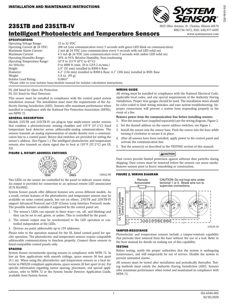
System Sensor
System Sensor 2351TB Installation and maintenance instructions
Hydrolevel Company
Hydrolevel Company Fuel Smart HydroStat 3200 Installation instructions and operating manual
Lake Shore Cryotronics
Lake Shore Cryotronics 372 quick start guide

Huber
Huber Pilot ONE Technical bulletin

Linear Technology
Linear Technology LTC4361 manual
