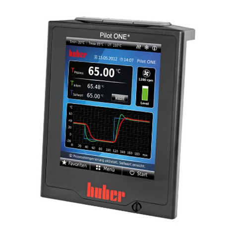
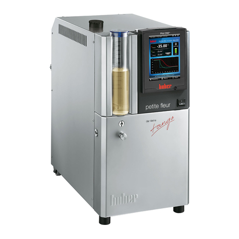
Huber Pilot ONE Service manual

- Remote control
using Pilot ONE®
- Remote control
using PC + Pilot ONE®
For indoor and
outdoor use
V1.1.0
Technical Bulletin


TECHNICAL BULLETIN
V1.1.0en/22.07.15 Liability for errors and misprints excluded. Pilot ONE as remote control
3
- Remote control
using Pilot ONE®
- Remote control
using PC + Pilot ONE®
For indoor and outdoor use

Remote control using Pilot ONE®
TECHNICAL BULLETIN
Pilot ONE as remote control Liability for errors and misprints excluded. V1.1.0en/22.07.15
4
1Remote control using Pilot ONE®
1.1 Valid for indoor and outdoor use
Some temperature control tasks make it necessary to place the control panel Pilot ONE closer to the
application. Temperature control units designed for outdoor use have the control panel Pilot ONE
mounted within the electrical cabinet. By default, the control panel Pilot ONE can be detached from
the Unistat Control ONE and used as a wired remote control. The protection class of the electrical
components of Pilot ONE (without protective housing) is IP20.
You can use the special connection cable (Order No. 16160) with 3 m cable length. You can re-
quest solutions with cable lengths over 3 m. The responsible body is to verify the EMC compliance
of the entire system and must check it during commissioning.
Fiber optic cables can be used for the remote control via Pilot ONE. You will need the special fiber
optic cable set (available on request). This set includes two connection extensions and two con-
verters. Again, the responsible body is to verify the EMC compliance of the entire system and
must check it during commissioning.
The line must be routed to ensure the best possible shielding and spatial separation from cables
subject to interference (e.g. power lines, frequency converters, etc.). The shielding must always
be connected on both sides. The shielding of the temperature control unit is already installed at
the factory.
A functional earth must be connected to the pin with the "Functional earth" symbol when using
the optional wall or table mount (Order No. 9493 or 9494) for Pilot ONE. The connection with the
contact surface for the functional earth must be as large as possible (low resistance, low imped-
ance).
Communication via the RS232 interface requires the optional Com.G@te.
For more information on electromagnetic compatibility see www.huber-online.com.
Indoor use:
Installation of Pilot ONE
using a wall or table
mount

Remote control using Pilot ONE®
TECHNICAL BULLETIN
V1.1.0en/22.07.15 Liability for errors and misprints excluded. Pilot ONE as remote control
5
Obligations of the responsible body
Shielding connected on both connection sides.
Testing signal immunity when using cable lengths > 3 m
Indoor use up to 3 m:
Remote control via Pilot
ONE – using a connect-
ing line
Indoor use more than
3 m: Remote control via
Pilot ONE - using a fiber
optic cable connection

Remote control using Pilot ONE®
TECHNICAL BULLETIN
Pilot ONE as remote control Liability for errors and misprints excluded. V1.1.0en/22.07.15
6
1.2 Valid for indoor and outdoor use in optional IP65 housing
The optional Pilot ONE housing has a protection class IP65 according to DIN EN 60529. Thus, the
housing protects the pilot ONE against dust and splash water. Refer to the Operation Manual of your
temperature control unit for ambient conditions. No frequency converter may be located in the im-
mediate vicinity of the IP65 enclosure at the place of installation. The tightened bolts must be pro-
tected with an anti-corrosive coating.
Scope of supply:
Pilot ONE in IP65 housing
Wall mount (including mounting hardware)
Cable sleeves (in IP65 housing); KT4 (#53151) for USB/Host and connecting cable up to 3 m;
KT6 (#53152) for Ethernet; KT10 (#53154) for connecting cable over 3 m
Spare rubber seal (in IP65 housing)
Spare self-adhesive seal (in IP65 housing)
Schematic representa-
tion of the optional
IP65 housing with
Pilot ONE

Remote control using Pilot ONE®
TECHNICAL BULLETIN
V1.1.0en/22.07.15 Liability for errors and misprints excluded. Pilot ONE as remote control
7
1.2.1 Attach the Pilot ONE in the IP65 housing to the wall bracket
Ensure there are no unwanted electrical currents (e.g. via metallic temperature control hoses; braid
of signal lines) between the IP65 housing, the temperature control unit and the periphery during in-
stallation. This requires the correct selection of a grounding concept that is suitable for the system.
The concept “S” (star-shaped) is recommended for short cable routes. The concept “M” (mesh-like)
is recommended for longer cable routes. For more information on electromagnetic compatibility see
www.huber-online.com.
Protect against electrostatic discharge when connecting applications to the temperature control unit
(e.g. reactors with agitators, but also during filling with thermal fluid). It is recommended to select
the cable cross-section of round cables / round strands as wide as possible. The use of broad ground
straps is ideal.
This is why all connections must be regularly checked for function. The connection with the contact
surface for the functional earth must be as large as possible (low resistance, low impedance). To do
so, use the [ground connection] on the IP65 housing.
PROCEDURE
Use the supplied mounting hardware to mount the wall bracket.
Connect the line extending from the [IP65 housing] with the temperature control unit.
Connect the [ground connection] with the building's grounding point.
Attach the [IP65 housing] to the mounted wall bracket.
Grounding concept
type “S”
Grounding concept
type “M”

Remote control using Pilot ONE®
TECHNICAL BULLETIN
Pilot ONE as remote control Liability for errors and misprints excluded. V1.1.0en/22.07.15
8
1.2.2 Exchange the Pilot ONE in the IP65 housing
The [rubber seal] below the [rear side of the housing] and the [self-adhesive seal] between Pilot ONE
and the IP65 housing must be replaced if the Pilot ONE needs to be replaced. Note the different
tightening torques ([A], [B] + [C]) of the screws used. Make sure not to mix the disassembled screws.
PROCEDURE
Switch off the temperature control unit.
Disconnect the temperature control unit from the current supply.
Disconnect the temperature control line from the Pilot ONE at the temperature control unit
([IP65 housing]).
Remove the line connected to the [ground connection].
Take the [IP65 housing] from the wall bracket.
Turn the [IP65 housing] around and place it face down on a dry and flat surface. The [rear side of
the housing] of the [IP65 housing] must be visible. Note that the Pilot ONE is no longer protected
against dust and splash water when the [IP65 housing] is opened.
Remove all screws from the [rear side of the housing].
Remove the [rear side of the housing].
Remove the [rubber seal].
Remove the line connected to the [Pilot ONE].
Remove all screws from the [mounting plate].
Remove the [mounting plate].
Remove the [Pilot ONE] from the [IP65 housing]. This step can be made more difficult by the
[self-adhesive seal] located under the Pilot ONE. Pull the [Pilot ONE] out and upwards.
Completely remove the old [self-adhesive seal] from the inside of the [IP65 housing]. Use a spatu-
la and afterwards some white gas.
Attach the new [self-adhesive seal] onto the clean and dust free inner side of the [IP65 housing].
Make sure that the new [self-adhesive seal] does not project into the housing opening for the
touchscreen.
Mount the new [Pilot ONE] onto the clean and dust-free [self-adhesive seal] in the [IP65 hous-
ing]. Use the mounted angle for the alignment.
Place the [mounting plate] onto the [Pilot ONE] and screw it tight with the screws removed be-
fore. Tighten the screws crosswise with the permitted tightening torque [C] only.
Connect the cable to the temperature control unit with the new [Pilot ONE].
Accurately place the new [rubber seal] onto the clean and dust-free [IP65 housing]. The new
[rubber seal] must not be damaged by screws.
Accurately place the new [rear side of the housing] onto the clean, dust-free and new [rubber
seal].
Firmly tighten the [rear side of the housing] to the [IP65 housing] with the screws removed be-
fore. Tighten the screws crosswise with the permitted tightening torque [A] only.
Connect the line extending from the [IP65 housing] with the temperature control unit.
Connect the [ground connection] with the building's grounding point.
Attach the [IP65 housing] to the mounted wall bracket.
Connect the temperature control unit to the power supply.
Switch the temperature control unit on.

Remote control using Pilot ONE®
TECHNICAL BULLETIN
V1.1.0en/22.07.15 Liability for errors and misprints excluded. Pilot ONE as remote control
9
1.3 Additionally applicable for outdoor use
Lines outside of buildings without lightning protection
DEATH BY LIGHTNING
All guidelines concerning internal and external lightning protection must be observed and ad-
hered to: Assembly, installation, maintenance and operation.
All grounding provisions must also be respected and adhered to.
Metric cable entries are mounted at each electrical cabinet. Small parts required for the cable en-
tries are included and located in the electrical cabinet. Ground bolts are attached to the housing of
the temperature control unit. You must connect the functional ground to this bolt.
The use of a VPC bypass in conjunction with an outdoor installation is not possible.
The interfaces POKO ONE, ONE ECS and Pt100 at the Unistat Control ONE are retained. They are lo-
cated inside the electrical cabinet. The optional Com.G@te is also located in the electrical cabinet, as
necessary.
All guidelines, standards and laws for outdoor installations must be observed. Also pay attention to
the internal and external lightning protection as well as cable routing, cable wiring, cable protection
and equipment installation.
DANGER
Outdoor use up to 3 m:
Remote control via Pilot
ONE – using a cable
connection
Indoor use more than
3 m: Remote control via
Pilot ONE - using a fiber
optic cable connection

Remote control of the temperature control unit via a PC
TECHNICAL BULLETIN
Pilot ONE as remote control Liability for errors and misprints excluded. V1.1.0en/22.07.15
10
2Remote control of the temperature control unit
via a PC
2.1 Valid for indoor and outdoor use
Some temperature control tasks make it necessary to control the temperature control unit via the
control panel Pilot ONE on a PC. For this purpose there is an Ethernet interface located at the Pilot
ONE as a standard. Temperature control units designed for outdoor use have the control panel Pilot
ONE mounted within the electrical cabinet.
You need a PC with an Ethernet interface and SpyControl installed to remotely control a tempera-
ture control unit via the control panel Pilot ONE. The responsible body is to verify the EMC com-
pliance of the entire system and must check it during commissioning.
The line must be routed to ensure the best possible shielding and spatial separation from interfer-
ing signals (e.g. power lines, frequency converters, etc.). The shielding must always be connected
on both sides. The shielding of the temperature control unit is already installed at the factory.
Obligations of the responsible body
Shielding connected on both connection sides.
Testing signal immunity when using cable lengths > 3 m
Indoor use:
Remote control of the
temperature control
unit via a PC - by using
an Ethernet point-to-
point connection
Indoor use:
Remote control of the
temperature control
unit via a PC - by using
an Ethernet network
connection

Remote control of the temperature control unit via a PC
TECHNICAL BULLETIN
V1.1.0en/22.07.15 Liability for errors and misprints excluded. Pilot ONE as remote control
11
2.2 Additionally applicable for outdoor use
Lines outside of buildings without lightning protection
DEATH BY LIGHTNING
All guidelines concerning internal and external lightning protection must be observed and ad-
hered to: Assembly, installation, maintenance and operation.
All grounding provisions must also be respected and adhered to.
Metric cable entries are mounted at each electrical cabinet. Small parts required for the cable en-
tries are included and located in the electrical cabinet. Ground bolts are attached to the housing of
the temperature control unit. You must connect the voltage equalizing cable to this bolt.
The use of a VPC bypass in conjunction with an outdoor installation is not possible.
The interfaces POKO ONE, ONE ECS and Pt100 at the Unistat Control ONE are retained. They are lo-
cated inside the electrical cabinet. The optional Com.G@te is also located in the electrical cabinet, as
necessary.
All guidelines, standards and laws for outdoor installations must be observed. Also pay attention to
the internal and external lightning protection as well as cable routing, cable wiring, cable protection
and equipment installation.
DANGER
Outdoor use:
Remote control of the
temperature control
unit via a PC - by using
an Ethernet point-to-
point connection
Outdoor use:
Remote control of the
temperature control unit
via a PC - by using an
Ethernet network connec-
tion

Peter Huber Kältemaschinenbau AG
Werner-von-Siemens-Straße 1
D-77656 Offenburg / Germany
tel. +49-781-9603-0
fax +49-781-57211
e-mail: info@huber-online.com
www.huber-online.com
Hotline: +49-781-9603-244
Other manuals for Pilot ONE
4
Table of contents
Other Huber Temperature Controllers manuals