Contents
1. Before you begin
2. Install the PMC-340B-B
3. Install the Auditor 6M+One device
4. Connect the Modbus cable
5. Connect the switching outputs (if used)
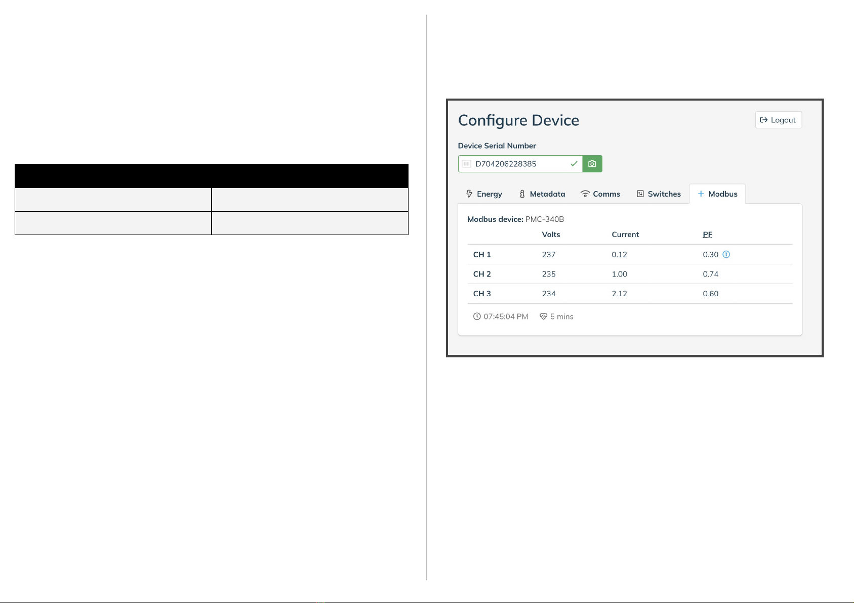
6. Use the onboarding tool
7. Validate installation
Help and support?
Need help with your installation? Lodge a support ticket via
●Use the onboarding tool to check the installation while the installer is on site
●Please make sure the metadata (circuit details) are complete
●Please quote one serial number per support request
Our team is available for urgent matters from 0900 to 1700, Monday to Friday,
Sydney time on 02 8316 7540 (+61 2 8316 7540 from overseas)
Document Revision
1. Before you begin
Ideally, a site survey will have been conducted that identifies:
➔The space required to fit the two meters and any contactors
➔The dimensions of the cables or bus bars to be monitored
➔The current ratings of the cables and bus bars to be monitored
➔The need for accessories like external enclosures and high-gain antennas
Ensure you have the recommended equipment:
➔Internet-connected smart device (e.g. smartphone, tablet, laptop)
➔a login to onboarding.wattwatchers.com.au for configuration/validation
➔a marker for numbering Current Transformers and cables during installation
➔a hand-held clamp/multi-meter for checking current measurements
➔An additional DIN-rail enclosure (in case there is no room on the existing rail)
➔A spare three-phase breaker (10A or 16A) where an existing breaker is not
available
Auditor 6M+One hardware checklist (box contents):
➔Modbus-enabled A6M+One device
➔Wiring tail—three phase
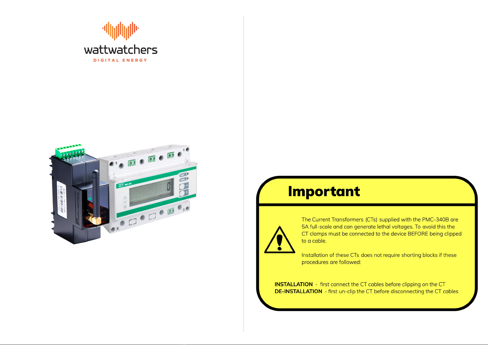
➔PMC-340B-B three-phase transformer-coupled billing meter
➔Billing CTs (typically 600A/5A to suit the circuit and cables or bus-bars)
➔Monitoring CTs + green CT connector (where the A6M+One is for monitoring)
➔Modbus cable
Check that:
➔9U (157.5mm) is available on the DIN rail for the A6M+One with
PMC-340B-B35XAE
➔The circuit cables fit through the CT openings
➔There is space for the contactors if you are using the switching functions