HOLUND Pure Sine Wave User manual

Pure Sine Wave Inverter
Instructions
Retain these instructions for future reference
www.wenchi-power.com

1. Overview
The Pure Sine Wave (PSW) inverter provides a 230V supply which closely replicates the domestic
mains supply. This makes it ideal for powering more sensitive equipment which may not be compatible
with traditional Modified Sine Wave (MSW) inverters.
Pure Sine Wave (PSW)
2. Contents
Protective covers
(1000, 2000, 3000W models only)
3. Optional Parts
LCD Frame kit LCD Display &Frame kit Current Sensor kit
For 1000~2500W For 600W For 600~3000W


CAUTION
There may be sparks produced when making battery connections, ensure no
flammable materials are present. Incorrect connection of cables to the battery (reverse
polarity) may damage the unit and is not covered by the warranty.
Single Battery System
Supplied
cables
Inverter AC
Inverter
Battery Vehicle
Chassis
Fig1 –Example single battery system
Dual Battery System
For heavy duty applications a secondary battery can be fitted to increase the inverter running time. An
additional relay may also be fitted to allow this battery to be charged from the vehicle alternator when the
vehicle engine is running, Fig2 shows an example installation.
from ignition
switch
ignition lamp Relay
Inverter AC
Vehicle
Alternator
Vehicle
Battery Inverter
Battery
Fig2 –Example dual battery system
Vehicle
Chassis
Earth Connection
Ensure the inverter is earthed by connecting a cable from the inverter earthing bolt Nto a suitable earth
within the installation (normally the vehicle chassis).
5
F1
F1
F2

Fig3 –Example RCD installation
CAUTION
It is recommended the inverter is wired and tested by a qualified electrician
Remote Mounting LCD Display (1000/2000/3000W Models)
For installations where the inverter may be inaccessible, the LCD display can be removed from the
inverter and mounted remotely using the optional LCD Frame Kit
1. Ensure that the inverter power on/off switch is in the OFF (0) position.
2. Remove 2 x screws holding LCD in position
3. Pull LCD forwards and unclip data connector from circuit board
4. Connect 6 metre extension lead to circuit board
5. Fit blanking plate and fix with 2 x screws, a slot is provided for cable to exit
6. Fix LCD into mounting frame using 2 x screws
7. Fit frame where display is required and attach 6 metre cable to rear
8. Snap fit endplates to cover screw fixings
9. Turn the power on/off switch to the ON (I) position.
10. Inverter can now be controlled remotely from the LCD display
6
2

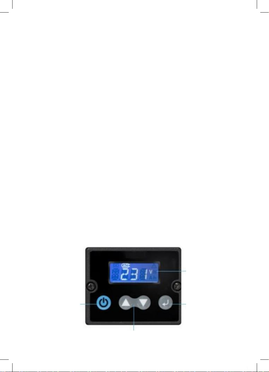
Adding an LCD Display (600W Model)
An LCD display can also be added to models without this function by using the optional LCD Display &
Frame Kit
1. Connect 6 metre extension lead to display port Jon inverter
2. Fit frame where display is required and attach 6 metre cable to rear
3. Snap fit endplates to cover screw fixings
4. Turn the power on/off switch to the ON (I) position.
5. Inverter can now be controlled remotely from the LCD display
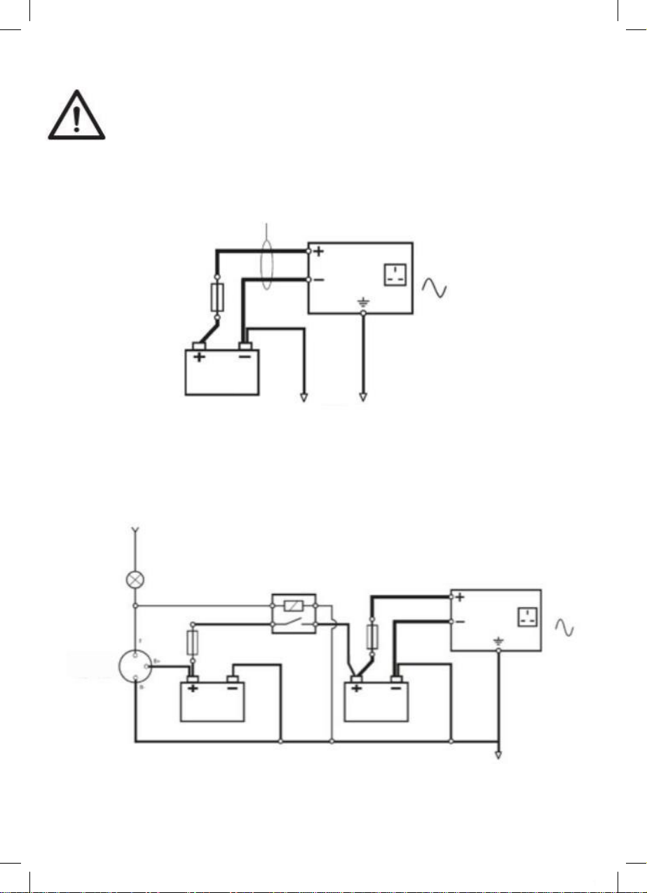
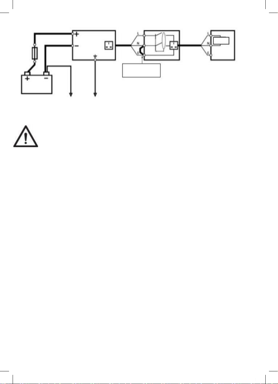
Current Sensor Installation (optional)
To enable monitoring of the input current and hours remaining function, the optional current sensor
should be fitted as shown in Fig4
1. Using black battery cable supplied with inverter, attach one end to battery(-) terminal and other
end to batt(-) terminal on Current Sensor
2. Using red battery cable supplied with inverter, attach one end to battery(+) terminal and other
end to inverter(+) terminal
3. Now connect cables 1-4 (supplied with current sensor) as shown in Fig4
1- Load(-) cable, negative connection from inverter to sensor
Use 1x4AWG cable for 600/1000W models
Use 2x2AWG cable for 2000/3000W models
2 - Comms cable, data connection from sensor port Kon inverter to current sensor
3- +12V Power cable, 12V power supply to sensor
4- Temperature sensor cable, temperature compensation for a more accurate current reading

5. General Information
Continuous & Surge Power
A Continuous rating is the amount of power the inverter can handle for a number of hours without
overloading. The Surge rating is a brief burst of power the inverter can provide to help start certain types
of load.
Loads Requiring Surge Power
The power rating shown on most electrical appliances is a continuous rating but some appliances require
up to five times this power for a brief period in order to start operating. This needs to be considered
when rating the inverter to avoid overloading it.
When using a microwave oven it should also be noted that the electrical power required from the supply
is around 50% higher than the actual cooking power of the microwave.
Typical Typical Surge
Example Appliance Rated Power Power Required (<1 sec)
ElectricDrill 500W 1000W
800W Microwave Oven 1200W 2400W
Angle Grinder 900W 2700W
Portable Air Compressor 200W 700W
Laser Printer 500W 2500W
6. Operation
Switching On
1. Ensure that the inverter power on/off switch is in the OFF (0) position.
2. Plug the appliance into the AC output socket on the inverter, ensuring it does not exceed the
maximum output power of the inverter
3. Turn the power on/off switch to the ON (I) position.
4. The Power indicator will illuminate green and mains power will be available from the AC output
socket(s). On models fitted with a display the LCD screen will also illuminate.
7. LCD Display & Indicators
Where fitted the LCD display provides additional information to help monitor and manage power from
the inverter.
LCD display
Power On/Off
(Press and hold to turn
inverter on/off)
Select key
Up/down keys
5

Information Mode
Various information modes are available by pressing up/down b to move forward or backwards through
the screens.
DC Voltage
DCCurrent
AC Voltage
Output Wattage
Hours Remaining
DC Voltage Input voltage available from the battery supply.
DC Current Input current being used from the battery supply in order to power the load.
*The optional Current Sensor must be fitted to enable measurement of
input current.
AC Voltage Output voltage available from the AC outlets.
Output Wattage Output power being consumed by the connected loads.
Hours Remaining An estimate of time remaining before the battery will be depleted based on
the current load.
*The optional Current Sensor must be fitted to enable measurement of
hours remaining.

Output Voltage Sets the AC output voltage. Only change if the application requires a different
voltage for optimum performance
Last Error Code Allows the last error code to be viewed
Battery Size Sets the Ah rating of the battery supplying the inverter. The value is used when
calculating input current and hours remaining in conjunction with the Current
Sensor
Power Saving Mode If the inverter does not detect a load for 10 minutes it will enter a sleep mode to
reduce drain on the battery. In this mode the power indicator will flash green
Low Voltage Cut-Off Sets the voltage at which the inverter will switch off should the input voltage
become too low
Output Frequency Sets the output frequency of the inverter. Only change if the application requires a
different frequency for optimum performance
2
RCD Test Tests the earth leakage protection function is working correctly.
This test should be carried out at least every three months.

Indicator & Error modes
Power Illuminates green to show the unit is switched on and power is available from
the AC output socket(s)
Overload Illuminates red if the units has been overloaded due to excessive current or a
short circuit
Over Temperature Illuminates yellow if the unit has overheated
Audible Alarm An alarm sound will be heard if the unit has switched off due to a fault
12

AC transfer function : In front panel “AC INPUT” is connected, the unit will
switch to external current supply automatically. The power discharge from
the battery will be stopped. This state will be indicated by 3 (Green-Red-
Yellow) light-emitting diode (LED), Flash every 2 seconds. As long as mains
voltage is supplied, the inverter can not be restarted.
AC transfer time < 0.1s
Inverter will start SLEEP MODE in 10 min.
AC INPUT

Earth Leakage Protection
To provide protection in the event of a fault, the 230V
outlets on this inverter are protected by an integral
Residual Current Device (RCD). Should a fault occur the
inverter will switch off to protect all connected circuits
and display an error code.
Note: The RCD function must be tested at least every
three months to ensure it trips correctly, this can be done
in two ways:-
i) Enter Setup Mode > RCD > Press 8 key
ii) From Information Mode, press and hold ‚or •key for 3
seconds
If the RCD function is OK, the inverter will trip and PASS
will be displayed.
If RCD does not trip correctly FAIL will be displayed, if this
happens the inverter should not be used until it has been
checked by a qualified electrician.
RCD Tripping current: 30 mA

10. Specifications
2


Table of contents
Popular Inverter manuals by other brands

Fuji Electric
Fuji Electric FVR0.75AS1S-4 Brief manual

SEW-Eurodrive
SEW-Eurodrive MOVIFIT-FC operating instructions

Selectronic
Selectronic SP PLUS Energy Centre Installation notes

Xantrex
Xantrex Xantrex PRO XM 1000 owner's guide

Paton
Paton ECO-160 Data sheet and operating manual

Pramac
Pramac GSW Use and maintenance manual

Anslut
Anslut 018354 operating instructions

Solectria Renewables
Solectria Renewables PVI 23TL Installation and operation manual

Winco
Winco DP3000/T Installation and operator's manual

Toshiba
Toshiba PDP002Z Function manual

Shenzhen Huangjintai Electronic
Shenzhen Huangjintai Electronic NK-GP1000 user manual

Moso
Moso SF8KTL manual