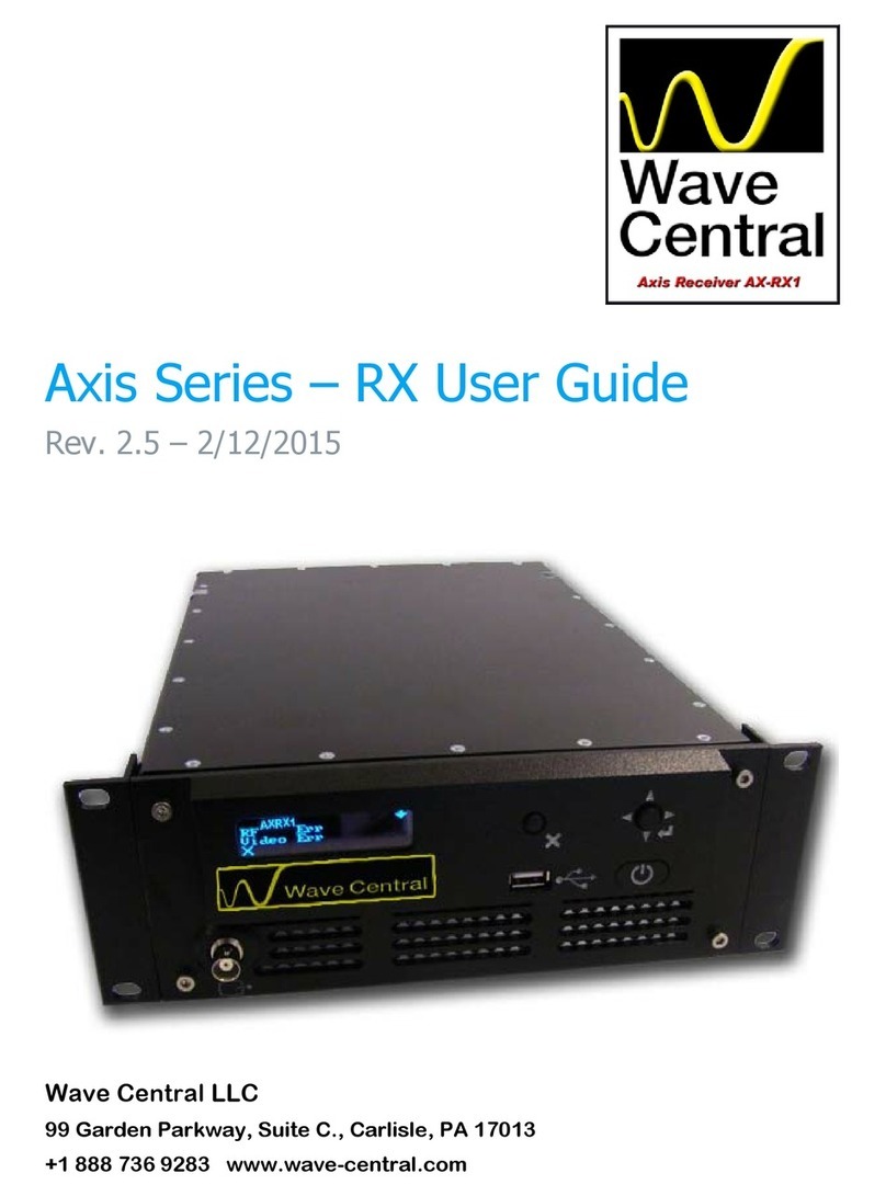
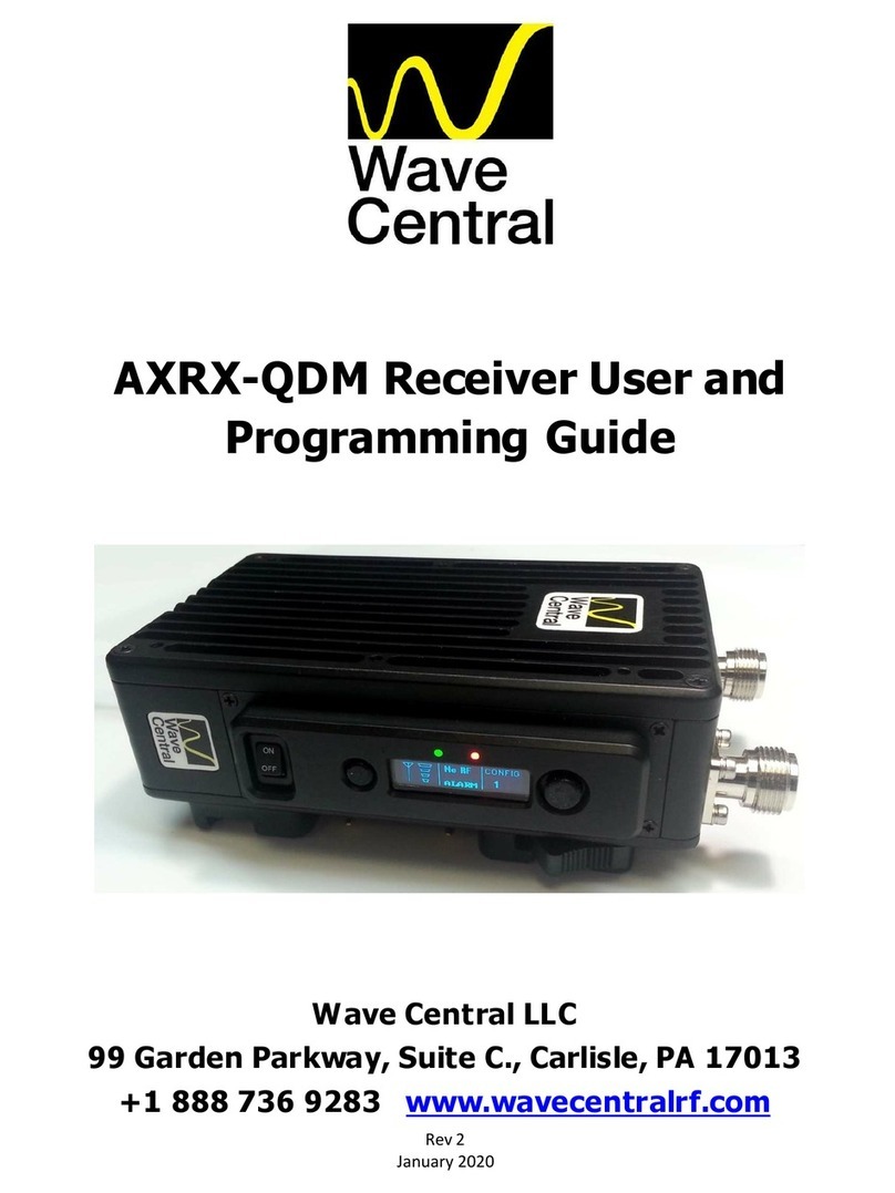
Wave Central AXIS AXRX3 User manual

1
Wave Central LLC
April 2019
AXIS AXRX3 Receiver
Kiss manual
(Keep It Simply Simple)
ETTIN STARTED
AXRX3 Out of the shipping box
AXRX3-6 Out of the box, rear panel view

2
Wave Central LLC
April 2019
This document will be featuring the AX S AXRX3-6 6 Way Diversity 5.8GHz
Single Decoder (D331 Main board) Receiver.
LCD Display protective cover removed
Initial power and Ethernet control connections.
When your receiver ships from Wave Central, it is pre-programmed with
your frequency band (16 pre-sets). The receiver’s services are tested and
verified prior to shipment. The parameters will be explained later in this
document. As you are aware the receiver can be programmed via the LCD
touch display screen.
When the receiver is final system tested (FST) all control parameters and
operational status is set and verified via the Web browser. This connectivity
is via the control RJ-45 top jack on the rear of the back panel. The
receiver’s P setting below, as shipped.

3
Wave Central LLC
April 2019
Set up of computer Ethernet adapter to communicate with the AXRX3
receiver. Wave Central engineering’s test computer uses Windows 7.
Other Microsoft OS’ should set up similarly.
The above menu screen shots take you to the location to enter the P
address for your computer, subnet mask and default gateway. When set,
press OK. Enter the P address into your web browser and you should be
communication with the receiver.

4
Wave Central LLC
April 2019
AT YOUR FACILITY
At initial power up after the power switch on the front panel is turned on the
green LED will illuminate. Also the internal cooling fans will spool up and
with be audible.
Boot Wheel is displayed after several seconds and turning clockwise during
the booth up cycle.
Menu displayed after boot sequence has completed.

5
Wave Central LLC
April 2019
Changing the IP address to interface within your
facility to another computer
f you plan to integrate the receiver into to the engineering Ethernet for set-
up and control, the P parameters must be entered via the LDC touch
screen display. Should you not want to change the network adapter
parameters on a computer that is already set up on engineering or specific
network execute the following. Unit MUST be power cycled to take effect.
From the main menu on the previous page select GLOBAL SETT NGS. The
GENERAL SETT NGS Setting menu is displayed.
From the GENERAL SETT NGS menu push the button and press over to
the P SETT NGS menu. From this menu select the which will bring up the
menu below.
Enter the desired P address. Then press button. The WARN NG
message appears. f additional P parameter need to be changed wait until
the WARN NG message disappears. The new P address will then be
displayed.
The next entry is for the NETWORK MASK and GATEWAY address. These
addresses will be entered in the same sequence. Pressing the button will
delete the entry and return to the main P SETT NG menu.

6
Wave Central LLC
April 2019
This is what P settings will be displayed on the LCD touch screen on the
receiver as shipped from Wave Central.
The next steps:
Prior to the sales process and subsequent purchase(s) all aspects of your
expectation of this receiver and any other Wave Central products in your
operational environment will have been fully explored. Most of the AX S
receivers are part of a system consisting of a camera transmitter(s),
camera paint and antennas. The antenna system requires the use of Block
Down Converters (BDC). ntermediate Frequencies (70-850MHz) are
specific for the operating band (5.8GHz) in this receiver as described in this
document.
This receiver is recommended to be operated in a cool dry controlled
environment where partible. t is not water proof.
Connections to and from the receiver are via supplied external 12 VDC
power supply, Ethernet, XLR analog audio and BNC 50 Ohm female F nput
(1-8) BDC bulk head connectors. Coax cable from the BDC is cable with 50
Ohm BNC connectors. Wave Central recommends Belden 1694A. Pre-
made and tested F cables are available from Wave Central for an
additional charge.
All video in and out coax cable connectors are 75 Ohm. Particular attention
MUST be adhered to when using coax connectors. The 50 & 75 Ohm
connectors are different. Pairing a connector with the incorrect mate can
cause damage to the connector and reduce efficiency of the circuity
involved.

7
Wave Central LLC
April 2019
The Web Browser
Connection to the AXRX3-6 receiver is via Ethernet, describe earlier in this
document. Once the receiver has completed it boot sequence, this screen
will be displayed.
Open the internet explorer on the attached computer and type
192.168.1.20 into the browser address line and hit enter. The following
screen will appear.
The screen default is the Status and sub menu: Overview.
Prior to going forward, you need to know what the television standard your
facility is using. n our test setup Wave Central our test standard is HD/SD :
1080i 59.94.
1080i 59.94. 1080i 59.94.
1080i 59.94. The test transmitter source is using this line standard and is
operating on pre-set 14 which is 5880 MHz. The transmitter is transmitting
at 10 mW on 5880 MHz, 8 MHz bandwidth, 16QAM constellation, 1/8 guard
interval, ½ FEC (Forward Error Correction) and bit rate of 11.06 Mbps.
Block Down Converters are connected to F inputs 1 and 6.

8
Wave Central LLC
April 2019
Select the nput tab on the display shown the status of the Demod 1,
Transmitter with services, AS status and Genlock.
Connecting the enlock source
The Genlock source MUST be the same standard used within your facility
and that of the RF cameras etc. Connect the Genlock source to the
standard as used in your facility to the Genlock input (75 Ohm) on the
receiver.
HD/SD 1, HDM 1, CVBS (NTSC) and the BDC to F inputs 1 and 6 should be
connected at this time. We also check and verify each analog outputs;
Audio 1 through 4 are functional. Your system will most likely be using
embedded audio.
Rear panel as configured for testing

9
Wave Central LLC
April 2019
The Genlock menu indicates that the input Genlock signal has been
detected (1080i 59.94) and supported. Since the receiver (D331 main
board) has one Decoder 1 displays Using.
Adjusting enlock
Wave Central uses a Leader Multi Monitor LV5570. The reference (Genlock)
is the same signal feeding the Genlock input to the receiver. The HD/SD 1
output, in our case feeds input B of the LV5570 and the monitor is set to
external.
Ref: Ext HD : DEFAULT

10
Wave Central LLC
April 2019
Select the Global Settings tab. From this menu at the Genlock tab, cursor
over to the Decoder 1, Genlock Mode (Off) the check and click. A drop
down menu will appear high light external
external external
external and click.
Then click the Apply tab.
Click OK The Receiver Genlocked to the reference

11
Wave Central LLC
April 2019
Leader’s LV5570 monitor showing the Genlocked relation with the receiver
and the reference. The current phase relationship; V
VV
Vertical Phase: 0 Lines,
H
HH
Horizontal Phase: 1.510 us or 112 Pixels.
The procedure below sets the Genlock parameters for the receiver.
Enter the pixel offset of 112 in the box above. Select Apply to set. Then click OK.

12
Wave Central LLC
April 2019
Receiver locked and phased with House reference source
Navigating more menus
Now that you can communicate with the receiver from the web menu more
menus can be explored. t’s important to browse the menus to get familiar
with the receivers capabilities.
Most of the menus are self-explanatory.

13
Wave Central LLC
April 2019
The name of the receiver can be changed as you desire. n this example
the name is changed to End Zone Camera
End Zone CameraEnd Zone Camera
End Zone Camera.
Downconverters menu: Shows configuration, these parameters are set
during systems testing. Note
NoteNote
Note: 12 VDC is sent to the Block Down Converters
with the F output BNC connectors located on the rear panel.
Clicking on the X will delete
what is in the box. Type the
desired name in the box. Then
click A
AA
Apply
pplypply
pply, and then OK
OKOK
OK in the
Configured successfully box.

14
Wave Central LLC
April 2019
Status Menu:
nput
Spectra
Services

15
Wave Central LLC
April 2019
The receivers tested are set to pre-set Channel 14 (5880 MHz). The
bandwidth is set to 8MHz. The G & FEC are set to auto. Decoder 1 menu’s
BNC Output is labeled HD/SD 1 on the rear connector panel of the
receiver.
This BNC
output can
select
Composite, AS
and HD-SD
(default). This
setting does
not change the
HDM 1 output.

16
Wave Central LLC
April 2019
The AS output is now available on the HD/SD 1 BNC connector on the
receiver.
Setting the Clock: Click on Set Clock
Set ClockSet Clock
Set Clock. n the pop menu all the parameters
are entered. Time format is 24 hours separated with colon (14:07). Click
S
SS
Set
etet
et, and then click OK
OKOK
OK.
Table of contents
Other Wave Central Receiver manuals
Popular Receiver manuals by other brands
Icom
Icom COMMUNICATIONS RECEIVER IC-R3 instruction manual

CROW ELECTRONIC ENGINEERING LTD.
CROW ELECTRONIC ENGINEERING LTD. Merlin Pro Installation and programming guide

US Automatic
US Automatic 030214 Use and installation manual
Icom
Icom IP501H Guide

Taramp's
Taramp's HOMEE TPS 6000 instruction manual
Hi-Tec
Hi-Tec SRX12 instruction manual
