Wave Central AXRX-QDM Owner's manual

AXRX-QDM Receiver User and
Programming Guide
Wave Central LLC
99 Garden Parkway, Suite C., Carlisle, PA 17013
+1 888 736 9283 www.wave-central.com

Contents
1. System Description .……………………………………………………………………. 4
1.1 What is the AXRX-QDM Receiver.......……………………………………… 4
1.2 Features & Benefits ....………………………………………………………….. 5
1.3 Overview ..…..………………………………………………………………………. 7
2. Getting Started ………………………………………………………………………….. 9
2.1 Identifying your Device …….………………………………………………….. 9
2.2 Labels …………………………………………………………………………………. 9
2.3 Installation .…………………………………………………………………………. 10
2.4 Software ……………………………………………………………………………… 11
3. Controls, Connections & Indicators ………………………………………………. 12
3.1 About Controls, connections & Indicators ……………………………….. 12
3.2 Front Panel .…………………………………………………………………………. 12
3.3 Control Panel …………………………………………………………………… ….. 13
4. Setting up your AXRX-QDM Receiver……………………………………………… 14
4.1 Connecting Antennas ……..…….………………………………………………. 14
4.2 Connecting DC Power……………………………………………………………. 15
4.3 Connecting AC Power …………………………………………………………… 15
4.4 Connecting Video Signals ……………………………………………………… 15
4.5 Connecting Audio Signals ……………………………………………………… 16
4.6 Connecting Data Signals ……………………………………………………….. 16
4.7 Connecting Control Signals ……………………………………………………. 17
4.8 About IP Control ………………………………………………………………….. 17
4.9 About Mission Commander.……………………………………………………. 17
5. Basic Operations …………………………………………………………………………. 18
5.1 Starting and Stopping …….…………………………………………………….. 18
5.2 Control Panel ………………………………………………………………………. 18
5.3 Menu Structure …………………………………………………………………… 20
5.4 Display System …………………………………………………………………….. 23
6. Advanced Setup …………………………………………………………………………. 26
6.1 Web Browser …….………………………………………………………………… 26
6.2 Connecting PC …………………………………………………………………….. 26
AXRX-QDM Receiver Users Guide

6.3 Primary Window ………………………………………………………………….. 29
6.4 Status Tab …………………………………………………………………………… 30
6.5 Global Settings …………………………………………………………………….. 35
6.6 Setting the Clock ………………………………………………………………….. 42
6.7 Configuration Tabs ………………………………………………………………. 42
6.8 Frequency Scanner ………………………………………………………………. 47
6.9 Log Tab ………………………………………………………………………………. 51
6.10 Upload Tab ……………………………………………………………………….. 51
6.11 Information Tab …………………………………………………………………. 51
7. Appendix A ………………………………………………………………………………… 52
7.1 Cautions and Warnings …………………………………………………………. 52
7.2 EMC/ Safety and Approvals …………………………………………………… 54
8. Appendix B ………………………………………………………………………………… 54
8.1 Equipment Care ….……………………………………………………………….. 54
8.2 Charging ……………………………………………………………………………… 55
8.3 Lithium Batteries ………………………………………………………………….. 55
8.4 Cleaning ……………………………………………………………………………… 56
8.5 Storage ……………………………………………………………………………….. 56
8.6 Repairs ……………………………………………………………………………….. 56
8.7 Technical Support ………………………………………………………………… 56
8.8 RMA Service ………………………………………………………………………… 56
9. Glossary …………………………………………………………………………………….. 58
9.1 Glossary ……………………………………………………………………………… 58
Document Disclaimer ...................................................................... 66
AXRX-QDM Receiver Users Guide
AXRX-QDM Receiver Users Guide
1.
Systems Description
This User Guide is about:
Equipment Title Operational Frequencies
AXRX-QDM Diversity Receiver 2GHz to 7.1GHz
Compact Sector Antennas 2GHz to 7.1GHz
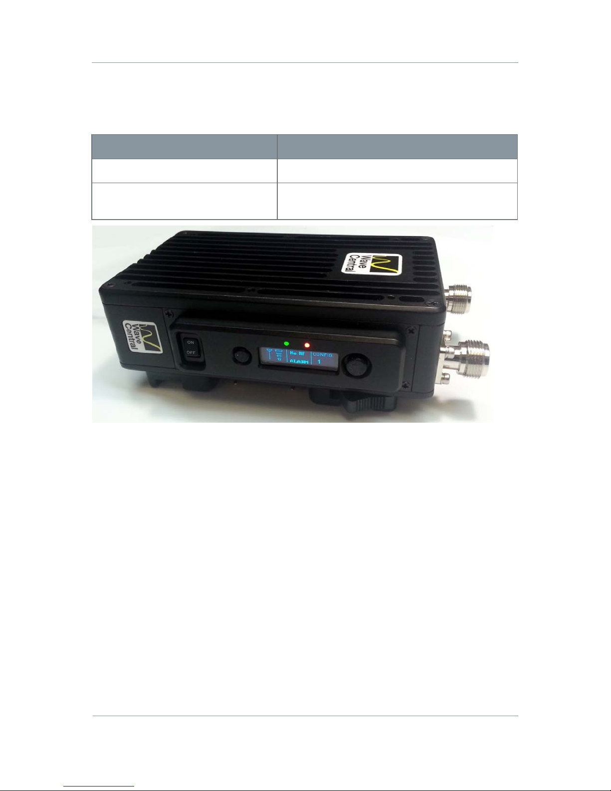
Figure 1-1 – AXRX-QDM Receiver
1.1
What is the AXRX-QDM Receiver?
The AXRX-QDM Receiver from Wave Central is a feature-rich COFDM digital video receiver,
which can operate in a variety of transmission bandwidths enabling the user to trade off
image quality against range, to suit all types of missions.
The AXRX-QDM Receiver has Wave Central at its core and is ideal for establishing long
duration rugged wireless video links, in harsh external environments, like mobile and urban
environments. The AXRX-QDM receiver is available in a variety of frequency bands.
Control is achieved through a front panel interface or by connecting the unit to an IP
network using the Ethernet interface given. You can quickly configure the device in the field
with laptop PC and configuration software.
The product can be used with an optional external chargeable battery pack; IDX or Anton
Bauer, providing between four and five hours battery life. The unit can also run from an
external DC supply which is included.
The front panel allows the user to switch channels and do basic configuration without the
need for connection to a PC, making it ideal for portable or mobile situations.
4

AXRX-QDM Receiver Users Guide
1.2
What are the Features and Benefits of AXRX-
QDM
Receivers?
It can be very useful to understand how the features of the unit yield tangible benefits to
you. This table summarizes these features and, more importantly, the benefits.
What are the Key Features of the AXRX-QDM Receiver?
Small dimensions: 5.7 x 3.5 x 1.6 inches (without cables or battery)
Low power
Fully featured 8/7/6/MHz demodulation
Maximum ratio combining antenna diversity
IP video streaming (RTSP and UDP) *
Ethernet control
Front Panel control
Specifications:
RF input (2) 2GHz to &.1GHz
DVB-T Bandwidth 6, 7 & 8 MHz
DVB-T Guard Intervals 1/32, 1/16, 1/8 and ¼
DVB-T FEC ½, 2/3, 3/4, 5/6 & 7/8
DVB T Constellations QPSK, 16QAM & 64QAM
Sensitivity <95dB
Video Line Standard PAL/NTSC
Resolutions (HD) 1920X1080i/59.94/50Hz
1920X1080p 30/29.97/25/24/23.97
1920X1080psf 30/29.97/25/24/23.97
1280x720p 60/59.94/50Hz
(SD) 720X480i 59.94Hz
720X576i 50Hz
Video Out (2) SD/HD SDI Video (1) Composite – BNC
Audio Out Analog (2) Stereo Line level via LEMO 5-pin OB, Headset Monitor
Embedded
Power – DC Input 9 to 16VDC
Power Consumption 20 Watts
Available Battery Plates IDX or Anton Bauer
5

AXRX-QDM Receiver Users Guide
1.2.1 Features and Benefits Table
KeyFeatures KeyBenefits
Compliant DVB-T Demodulator and
proprietary narrowband.
Full Demodulation 8, 7, and 6 MHz
Correct multi-mode operation - Perfect
integration with your current equipment.
Line Level Audio / Video Out, Headphone
output.
Easy to use - Operations staff can use known
standard equipment.
Digital COFDM Modulation Excellent performance - Resistant to multipath
interference, delivers high quality video and
audio, also when mobile or in built up areas like
urban environments.
Low Delay, high quality video encoding
in MPEG-2 and MPEG-4
High reliability - Use a radio system like it was
a line. You can select between MPEG 2 and 4
to suit your operation.
Low latency Enables real-time operations like remote
vehicle control or UAV operations.
Sixteen Presets Available Better use of assets and resources - You can
preset frequencies into sixteen presets.
Configure the full operation in the calm of the
headquarters then the operations staff only
have to quickly select the preset with one
button.
High reliability and availability Reduced maintenance requirement, reduced
spares holding, resulting in important cost
benefits across the life of the system.
Low Mass Applicable for discrete operation in the field.
Note: AXRX-QDM Receivers are frequency specified because they have internal down
converters.
6

AXRX-QDM Receiver Users Guide
1.3
Getting an Overview of the AXRX-QDM Receiver
Diagram: AXRX-QDM Receiver Primary System
Figure 1-2 Primary System Layout
Primary Unit bottom panel shown
1
23
13
9
4
5
8
7
6
12
11
10
13
7

AXRX-QDM Receiver Users Guide
No Item Function
1 AXRX-QDM Receiver. Primary Unit bottom panel shown.
2 N Connector 2-way female for antennaAntennas connect here. Do not
tighten too much – tighten with
your hand.
3 N Connector 2-way female for antenna Two antennas used for diversity
reception.
4 USB Mini-B 5-way receptacle Connects to your PC for
programming the AXRX-QDM
receiver.
5 RJ45 8-way receptacle (sockets). Connects from your PC.
6 LEMO OB 4-way receptacle (sockets) Power Input.
7 LEMO OB 6-way receptacle (sockets), For control/data in and out.
8 LEMO OB 5-way receptacle (sockets). Audio output.
9 1/8” Stereo Phone Jack Headset audio monitoring
10 BNC 2-way plug, (pins). SD/HD SDI
11 BNC 2-way plug, (pins). SD/HD SDI
12 BNC 2-way plug, (pins). For analog video output.
13 Battery Adapter Plate IDX or Anton Bauer
Table 1-3 – Primary System Diagram Key
8

AXRX-QDM Receiver Users Guide
2.
Getting Started
2.1
Identifying your Device
The AXRX-QDM Receiver is described in this User Guide.
Figure 2-1 – AXRX-QDM Receiver showing Control Panel
This is a AXRX-QDM Receiver [Quick Deploy Mini]
Its type designation is: AXRX-QDM
Dimensions: 5.7” (L) x 3.5” (W) x 1.6” (D)
Less cables and battery adapter plate
Weight: 1.4 pounds
Operating Temperature: -10 degrees C to +45 degrees C
Power Consumption: 8W DC Input 6 to 16VDC
2.2
About the Labels on your AXRX-QDM Receiver
Which model do I have? What is its Serial Number?
This topic contains information covering placards, labels, markings, etc., showing the part
number, legend and location of each placard, label, or marking required for safety or
maintenance important information.
9

AXRX-QDM Receiver Users Guide
Step 1: Identify the Device Label
Figure 2-2 – AXRX-QDM Receiver Label
No Item
1 AXRXP-2G family of products.
2 Frequency range, 2GHz in this example.
3 WC with four digit serial number. This number will be necessary during a
support call.
Table 2-3 – AXRX-QDM Receiver Label Key
2.3
Planning the Hardware Installation
During the layout of the system, you must give careful consideration of the location of this
and all other related modules. Some of the items to think about include:
Space - Keep 100mm clearance left and right for cable bending.
How near to other devices (for example, source equipment).
Length of cables.
Environmental conditions (temperature, humidity, etc.)
Access for repair.
10

AXRX-QDM Receiver Users Guide
2.4
About the Software with your AXRX-QDM Receiver
The AXRX-QDM Receiver has two software elements:
Firmware that operates on the primary board of the device.
Control Application that you operate on your Windows PC.
About the Firmware
Although much of the unit is built up of hardware components, many of the sophisticated
features are done in the firmware operating on a Field Programmable Gate Array (FPGA) in
the device.
When you must do an internal software upgrade we can give you an installer which contains
all the code to do this easily.
About the Control Application
The software tools give users with a convenient access to the most usual features and
functions of the Device. All software tools are implemented as a web interface. The
advantage of a web interface is that it is independent from the user’s operating system and
it is not necessary to have special software on the host PC.
The computer display control application of the unit gives access to many of the features of
the radio but for more sophisticated operations and configuration tasks you’ll connect up a
PC operating a web browser to access the Control Pages on your AXRX-QDM Receiver.
The Control Page enables you to set up sixteen presets in the radio and have control of
many parameters of the unit.
Here’s what the receiver’s Control Pages look like:
Screenshot: AXRX-QDM Receiver Control Pages
Figure 2-4 – AXRX-QDM Receiver Control Pages
11

AXRX-QDM Receiver Users Guide
3.
Controls, Connections and Indicators
3.1
About Controls, Connections and Indicators
You must find all the controls and connections on the unit. You also must identify and
interpret alarms or indicators. These topics will help you identify all these features.
The device has front and rear panels which contain all the interface connections for the
units and the controls and indicators.
The front panel contains the control functions used for in-field configuration and all
connections are installed on the rear panel.
3.2
Exploring the Front Panel
Diagram: Front Panel
Figure 3-1 AXRX-QDM Receiver Front Panel
No Item Used for...
1 Power Switch Power the receiver
2 Cancel Button Each time you push the Cancel button the Field
Controller steps up one menu level.
3 Navigation
Button.
Push the Navigation button in to select menus or
options.
Move the Navigation button up and down to move
between menus or change options.
Move the Navigation button left and right to select
numbers/letters when editing values.
4 Two line OLED
display.
User interface.
Table 3-2 – AXRX-QDM Receiver Front Panel Key
2
4
3
1
12

AXRX-QDM Receiver Users Guide
3.3
Exploring the Control Panel
The control panel is presented as a Field Controller and is on the front panel of the AXRX-
QDM receiver.
3.3.1 Field Controller Operation
The unit has a simple to use two button control system which has been designed for use in
the field where it can be necessary to make adjustments to the AXRX-QDM Receiver settings
quickly and easily. An in-depth description on how to operate the Field Controller and
navigate through the units settings is given later in this guide.
3.3.2 Alarm System
The Field Controller can be setup to show a flashing Low Battery alarm when the voltage
reaches a user-specified minimum level. There are no other visual or audible alarms on the
AXRX-QDM Receiver.
13
AXRX-QDM Receiver Users Guide
4.
Setting up your AXRX-QDM Receiver
4.1
Connecting the Antennas
This topic describes connecting systems designed mainly for sending the RF signals. Of all
the variables affecting single-channel radio communications, the one item which an operator
has the most control is the antenna. With the right antenna, an operator can change a
marginal net into a reliable net.
There are two antenna interfaces on the rear panel of the AXRX-QDM receiver. Antenna one
and two must be attached for optimum operation.
CAUTION: Antennas must be connected directly to the unit. If you have to use cables
between the antennas and the receiver (in a mobile situation for example), keep them short
and use very high quality cable.
Before you Start
This is necessary:
Two Compact Sector antennas that align with the frequency range of your AXRX-QDM
receiver.
Step 1: Attach the Antennas
1. Connect the antennas to the N connector receptacles on the top panel of the AXRX-QDM
receiver.
2. Do not tighten the antennas too much – tighten with your hand.
Step 2: Set Antenna Polarization
1. COFDM links are very robust and are tolerant to changes in antenna location, but, it is
important to try and keep the antennas in the same plane if possible.
2. The antennas used with the COFDM links are usually vertically polarized.
3. The Compactor antennas beam width azimuth of 110 degrees and a elevation beam width
of 18 degrees, as exampled for 2 GHz operation.
4. Rotation of the antennas should be directed toward the transmitter.
Next Steps
Connect the DC Power.
14

AXRX-QDM Receiver Users Guide
4.2
Connecting the DC Power
The AXRX-QDM receiver requires 12VDC. This can be supplied from a vehicle, an AC Adaptor
or a battery pack.
Before you Start
This is necessary:
A 12VDC Power Source
A AXRX-QDM receiver
Step 1: Connect the DC Power
1. Connect a fully charged battery IDX or Anton Bauer to the battery adapter plate
Next Steps
Connect Video and Audio Signals.
4.3
Connecting AC Power
Before you Start
This is necessary:
A 12V AC Adapter
AXRX-QDM receiver.
Step 1: Connect the AC Power
1. Connect the LEMO OB 4-way plug (pins) from the AC adaptor to the LEMO OB 4-way
receptacle (sockets) on the AXRX-QDM receiver which is on the bottom panel.
2. Connect AC mains plug to your local AC supply and switch on.
Next Steps
Connect Video Signals.
4.4
Connecting Video Signals
There are three video outputs on this unit:
Composite Video (monitoring) – BNC
SD/HD SDI – BNC, output 1
SD/HD SDI – BNC, output 2
15

AXRX-QDM Receiver Users Guide
4.5
Connecting Audio Signals
Before you Start
This is necessary:
AXRX-QDM receiver.
LEMO 5-way plug with 2 female XLR connectors.
Two audio monitors.
Head phones to monitor audio at the receiver.
Step 1: Connect Audio Signal
1. Connect the LEMO OB 5-way plug to the AV receptacle of the AXRX-QDM receiver.
2. Connect the XLR 3-way plugs to the audio mixer.
3. Switch on and tune the receiver to a transmission carrying audio.
4. Your audio will be heard at the audio mixer.
5. Connect headset into 1/8” Stereo jack on the side of the receiver.
6. Your audio will be heard on the headset.
4.6
Connecting Data Signals
Before you Start
This is necessary:
AXRX-QDM receiver
Data Cable Assembly (optional)
A PC or other data monitoring device.
Step 1: Connect Data Signal
1. Connect the LEMO 6-way plug to the DATA receptacle of the AXRX-QDM receiver.
2. Connect the D-Type 9-way plug (sockets) marked DATA to your PC or other data
monitoring device.
3. Switch on and tune the receiver to a transmission carrying data.
4. Your data will be received across the link.
16

AXRX-QDM Receiver Users Guide
4.7
Connecting Control Signals
The AXRX-QDM receiver’s internal settings for the receiver and the Field Controller can be
controlled by external software when connected to a PC. This connection could be through
the IP network or a USB serial connection.
The Mission Controller software package is available to support external control of the
AXRX-QDM receiver and the Field Controller, and give a full deployment management
tool.
Before you Start
This is necessary:
AXRX-QDM receiver
Ethernet Cable Assembly (optional)
A PC with a web browser.
Step 1: Connect Data Signal
1. Connect the RJ45 8-way plug to the ETHERNET receptacle of the AXRX-QDM receiver.
2. Connect the other RJ45 plug to the Ethernet receptacle on your PC.
4.8
About IP Control
The AXRX-QDM uses IP Control to share data with a Personal Computer for most
programming operations. This is the primary means of connecting to the device and gives
access to settings and configurations quickly and easily.
The IP interface enables you to control the unit with a PC with a web browser and for
streaming video. The RJ45 connector on the rear of the unit marked Ethernet is compatible
with 10/100 Base-T Ethernet networks.
The unit passes IP signals through the IP interface on the bottom
panel. This is an RJ45 Jack.
4.9
About Mission Commander
Mission Commander is a software tool designed to configure and manage Wave Central
devices.
The AXRX-QDM Field Controller can be configured and upgraded by connecting to Mission
Commander through the USB port on the side panel.
17

AXRX-QDM Receiver Users Guide
5.
Basic Operation
5.1
Starting and Stopping the AXRX-QDM Receiver
AXRX-QDM receiver units don’t have power switches – you simply apply power to them and
they will start up.
Before you Start
This is necessary:
A AXRX-QDM receiver
A source of power.
Step 1: Powering Up
1. Power-on the AXRX-QDM receiver with one of the procedures in Setting up your
AXRX-QDM
Receiver earlier.
2. You’ll see an image on the Field Controller screen on the front panel.
Step 2: Stopping the System
It is important to stop the system carefully. This makes sure that all processes are
terminated correctly and no data or settings become unavailable.
1. Make sure the unit is not updating software or applying configuration changes, and that
the unit is not in sleep mode.
2. Disconnect the power cable from the AXRX-QDM receiver.
3. On the front panel the Field Controller screen will go off. (Screen will stay on if
connected to PC with USB)
4. The system is stopped safely.
Next Steps
Exploring the Control Panel.
5.2
Working with the Control Panel
The control panel is presented as a Field Controller and is on the front panel.
Before you Start
This is necessary:
A fully powered AXRX-QDM receiver.
18

AXRX-QDM Receiver Users Guide
Step 1: Interpret the Display
Figure 5-1 Working with the Control Panel
No Name Notes
1 Up Arrow There are more options available in this menu.
Push the navigation button Up to see more options.
2 Down Arrow There are more options available in this menu.
Push the navigation button Down to see more options.
3 Enter Arrow There are sub-level menus available OR it is necessary to
make sure of a step, such as changing a setting.
Push the navigation button to access the sub-level menu
or save the changes you have made to that setting.
4 Scroll Left and
Right
It is possible to scroll left and right.
Push the navigate button right to scroll right or left to
scroll left. This is usually for entering textual or numeric
information.
5 Exit Symbol It is possible to Exit the current part of the menu.
Push the cancel button to go up one level. Changes made
will not be saved.
Table 5-2 – Working with the Control Panel Key
19
AXRX-QDM Receiver Users Guide
Step 2: Use the Field Controller Screen Lock
To lock the Field Controller, simply hold down the two buttons on the front panel for
approximately four seconds. A small key symbol will show in the bottom right corner of the
screen. To unlock the screen simply hold down the buttons again for four seconds.
5.3
Exploring the Control Panel Menu Structure
The Field Controller has three primary menus each of which have many sub-menus. By
navigating through these menus, it is possible to see the status of the unit’s parameters and
change settings without the use of a PC. The three menus are:
Unit Status
Unit Control
Local Settings.
Before you Start
This is necessary:
A fully powered AXRX-QDM receiver.
Step 1: Explore the Unit Status Menu Structure
Top Menu Second Level Function Default Value
Unit Status Freq Shows current receiver frequency 2405.000MHz
SNR A Shows current SNR (Antenna A) N/A
SNR B Shows Current SNR (Antenna B) N/A
B/W Shows current bandwidth N/A
Pre Err Shows the bit error rate for pre-
errors.
N/A
Post Err Shows the bit error rate for post-
errors.
N/A
Pkt Err Shows the number of packet errors
coming out of the error correction
system.
N/A
Input level A Shows the level in dBm of the signal
being received on antenna A
N/A
Input level B Shows the level in dBm of the signal
being received on antenna B
N/A
20
Other manuals for AXRX-QDM
1
Table of contents
Other Wave Central Receiver manuals


