Wave Italy IMPETUS User manual

Installation, use and maintenance manual EN
WAVE IMPETUS WAVE FORCE
Pedal Set for Virtual Simulation

Contents
Manual information............................................................................3
Product information...........................................................................3
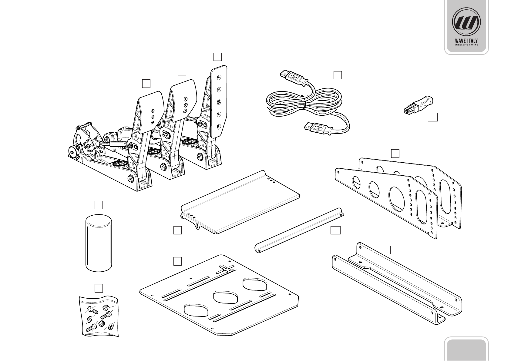
Equipment .............................................................................................4
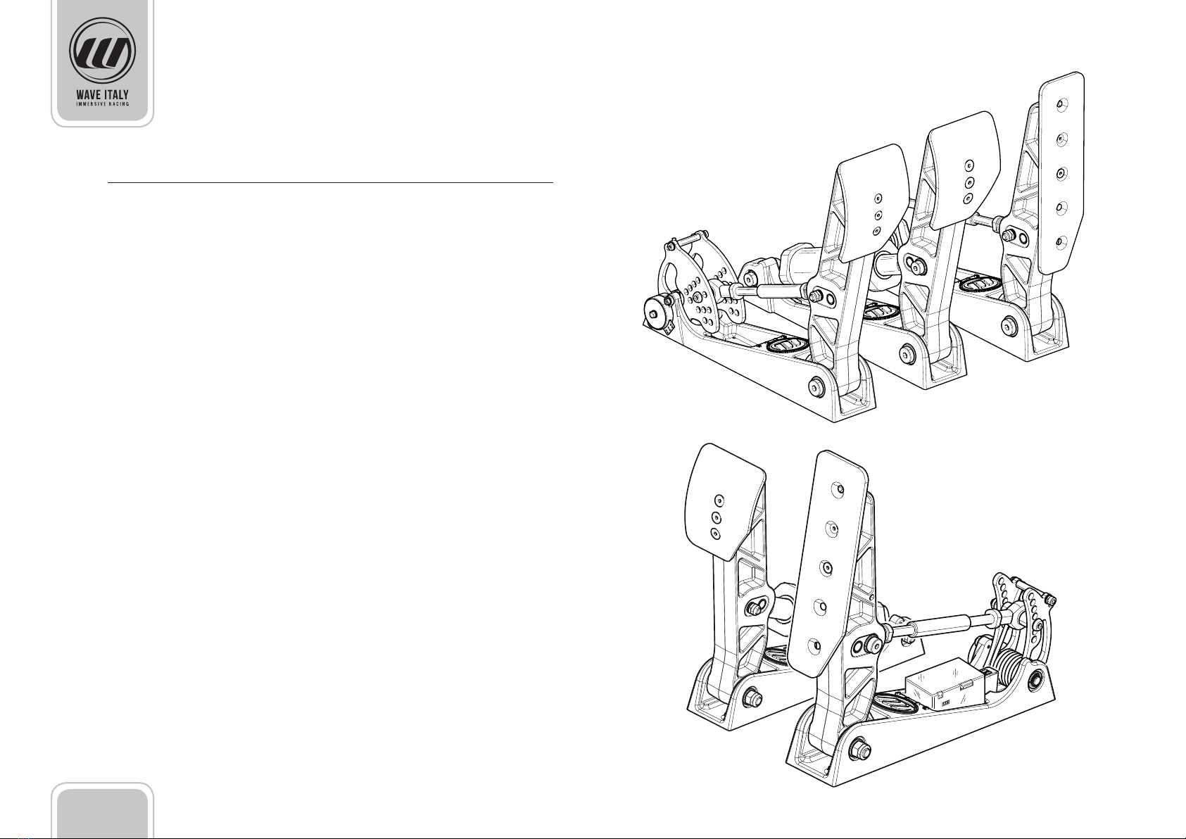
Product Description............................................................................6
WAVE IMPETUS pedal set............................................................ 6
WAVE FORCE pedal set................................................................ 6
Installation .............................................................................................7
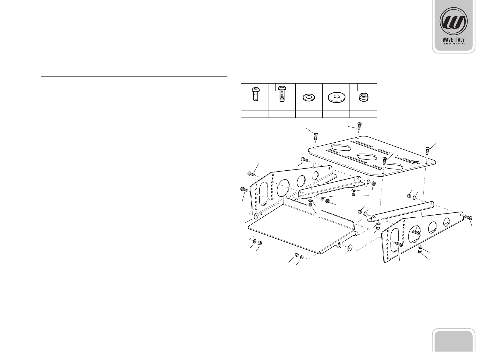
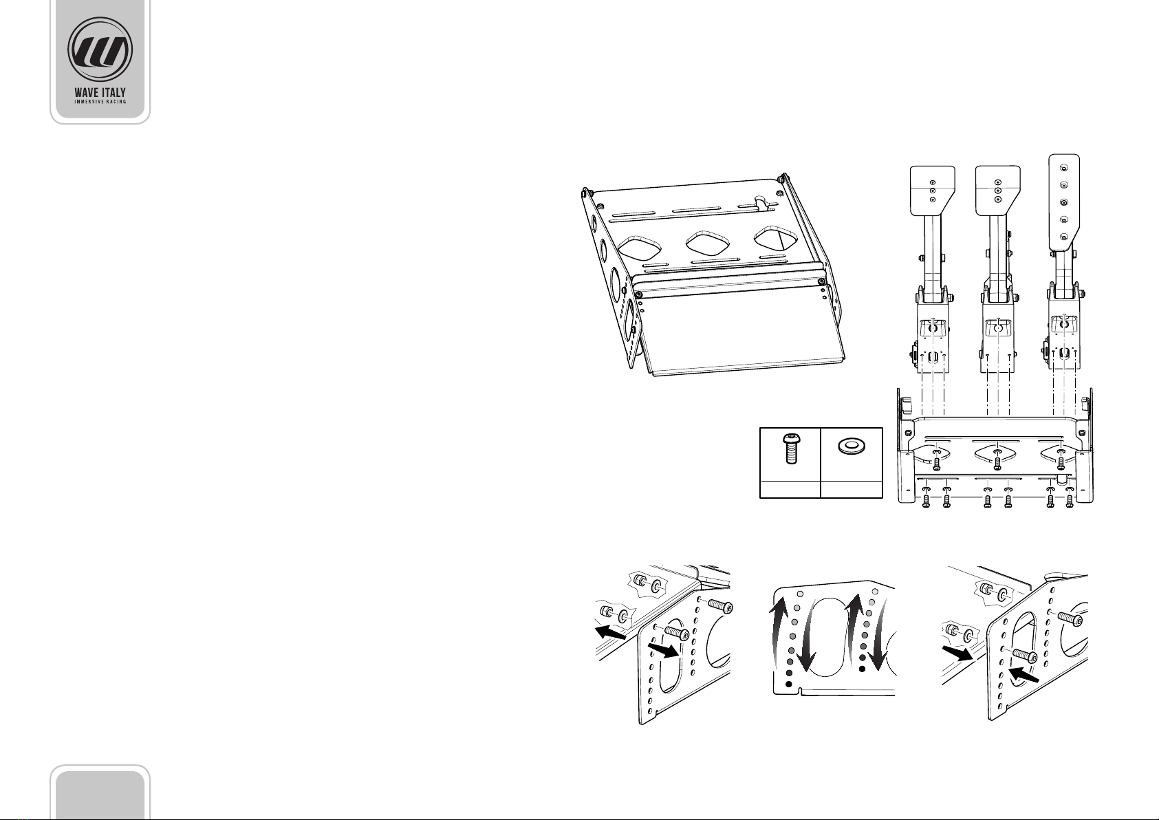
Base assembly............................................................................... 7
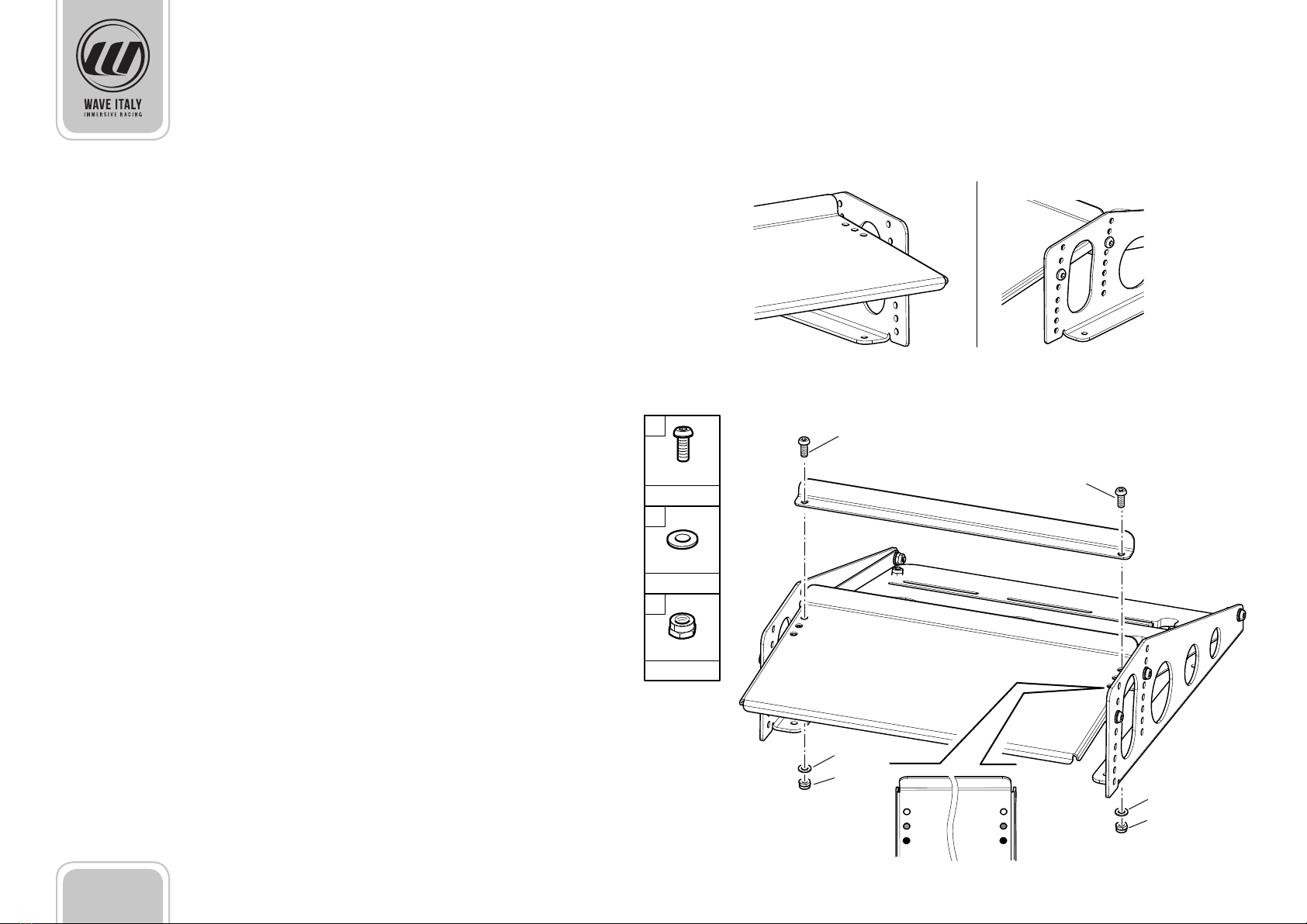
Assembly of the additional heel pad support ....................... 8
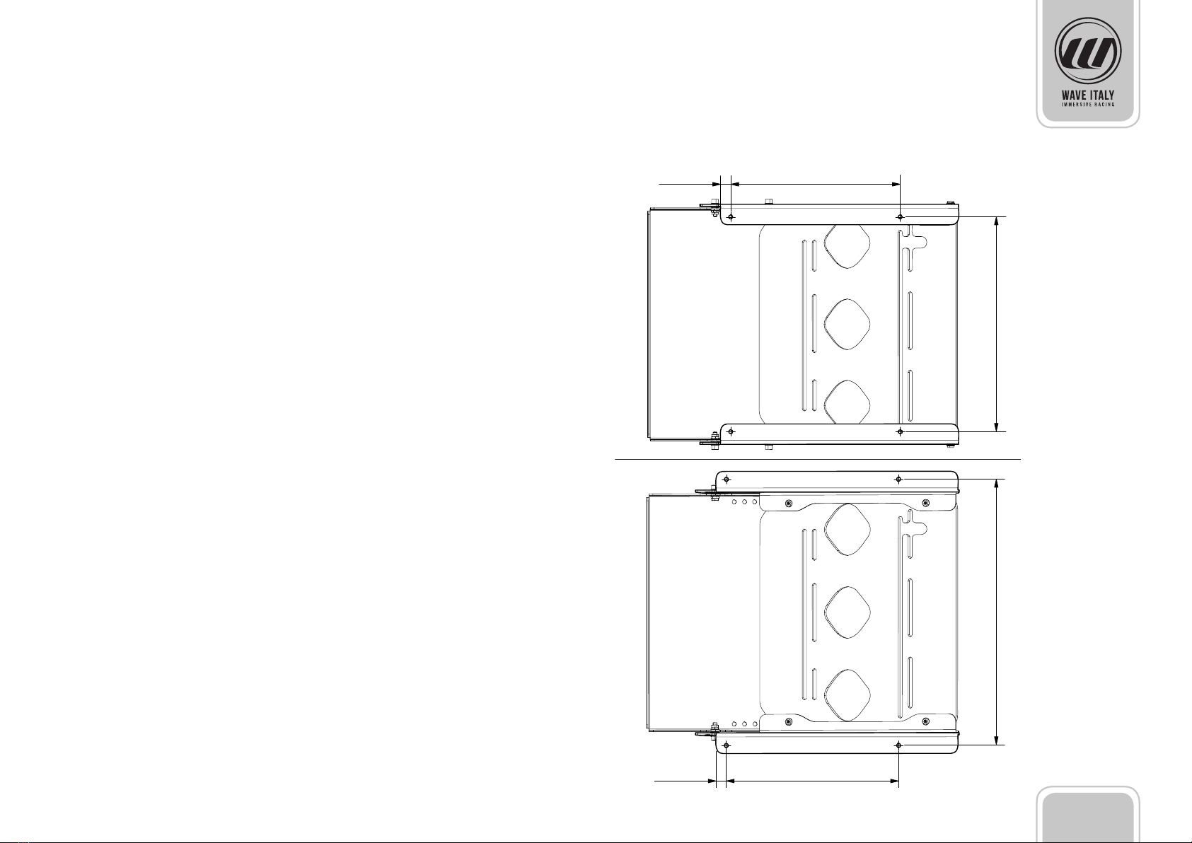
Installation heights of the base ................................................ 9
Pedal assembly........................................................................... 10
Customised base ........................................................................ 11
Pedal connections............................................................................ 12
Pedal calibration ............................................................................... 13
Settings and calibration........................................................... 14
Accelerator................................................................................... 14
Brake ............................................................................................. 15
Clutch (WAVE IMPETUS set with 3 pedals) ...........................15
Clutch (WAVE FORCE set with 2 pedals) ...............................16
Functional test ............................................................................ 17
Pedal adjustment ............................................................................. 18
Accelerator pedal adjustment.................................................18
Brake pedal adjustment ........................................................... 20
Clutch pedal adjustment.......................................................... 22
Suspended pedal set base accessory........................................ 23
Equipment ................................................................................... 23
Assembly of the suspended pedal set base..........................24
Installation heights of the base ..............................................26
Pedal assembly........................................................................... 27
Adjusting the heel pad supporting plate.............................. 28
Adjusting the angle of the pedal set...................................... 29
Adjusting the height of the pedal set. ...................................29
Technical data.................................................................................... 30
Maintenance ...................................................................................... 30
Product compliance ....................................................................... 30
Troubleshooting ............................................................................... 30
Warranty terms.................................................................................. 31
Copyright............................................................................................. 31
Disposal................................................................................................ 31
Customer Services contacts.......................................................... 31

3 - EN
Dear customer,
thank you for choosing the quality and professionalism of Wave S.r.l.
Our virtual simulation pedal set is designed to ensure an in-
creasingly realistic driving experience.
Before you install or use the product, please carefully read the
manual which will provide all the information required for the
rst installation, the possible congurations of the pedal set
and its use.
Manual information
This documentation must be printed and kept in a safe place
for reference at all times. It must be considered an integral part
of the product and must be transferred with it if it is sold.
The illustrations contained in this manual are for information
purposes only and are not binding. Wave S.r.l. reserves the right
to make any changes to the contents of the manual without
prior notice. The product specications are subject to change
without prior notice due to continuous product improvement
and renement. Therefore this documentation may dier
slightly to the characteristics of the product. Any substantial
changes to the product will in any case be accompanied by
appropriate documentation to be integrated in this manual.
The source language of the content related to this Wave s.r.l.
documentation is Italian.
Product information
The product has been designed and manufactured to be used
in indoor places protected from rain.
Always earth the pedal set with the cable provided.
Do not expose to direct sunlight and heat sources.
Do not leave the product in a damp place or exposed to dust.
Do not immerse or wet the product with liquids.
Do not use this product if it is damaged.

4 - EN
Equipment
1Clutch pedal
2Brake pedal
3Accelerator pedal
4USB connection cable
5kit for alternate conguration
6Package with required hardware
7Heel backing plate
8Side supports for base
9Base for pedals
10 Base angle pieces
11 Additional heel pad support
12 Connector plug for clutch axis (only for WAVE FORCE)
The pedals contained in the package will dier depending on
the conguration chosen upon purchase.
The brake pedal can be congured according to your driving
style by mounting internal modules that modify the pedal
feedback.
The pedals are included with the standard adjustable base for
installation on the oor or on simulation platforms.
Wave S.r.l. also provides the suspended pedal set support for
traditional seats. The accessory is sold separately and the in-
stallation instructions are given in the nal chapters of this user
manual.

5 - EN
1
2
3
4
5
6
7
8
9
10
11
12

6 - EN
Product Description
WAVE IMPETUS pedal set
3-pedal set for virtual simulation made entirely of anodised
aluminium for maximum movement accuracy, long service life
and a high level of reliability.
The pedal set features the complete conguration of the device
with accelerator, brake and clutch.
WAVE FORCE pedal set
2-pedal set for virtual simulation for driving with accelerator
and brake only.
High-quality materials and sleek design for a product that ex-
presses its value just like the best professional pedals installed
on real cars.

7 - EN
Installation
Base assembly
The pedals must be installed on a solid support base that does
not compromise the ergonomic characteristics and accuracy of
the product.
The base supplied features guides used to position the pedals
according to a set or customised distance according to cus-
tomer comfort. It is also possible to adjust the inclination of the
base to optimise the quality of the guide.
The presence of the heel backing plate increases the comfort
during intense simulations, as it helps the foot maintaining a
correct position during the performance.
Follow the instructions shown in the gure to mount the sup-
plied base.
Wave S.r.l. oers the customer additional adjustable sup-
ports, designed and built for an increasingly real experience.
1
1
1
2
1 2 3 4
M6x16 Ø6 Ø6x18
x 6
M6x20
x 4 x 10
5
M6
x 10x 2
2
2
1
1
3
3
3
3
3
3
5
5
5
3
3
5
4
5
5
5
5
1
2
4
3
5

8 - EN
Side supports are changeable to allow locating the xing trails
on the pedestal, either inwards or outwards.
Assembly of the additional heel pad support
An additional support for assembly on the heel pad is provided
for driving in greater comfort. It improves the position of the
foot by bringing it further forward.
Follow the instructions shown in the gure to mount the
additional support. Put it in place using the holes at the same
height.
1
M6x16
x 2
2
x 2
Ø6
3
x 2
M6
1
2
3
2
1
3

9 - EN
Installation heights of the base
The holes in the base shown in the gure are for installation on
a simulation structure or on xed supports.
• View from above: pedal set with assembly of the set sup-
ports with aps facing inwards
• View from below: pedal set with assembly of the set sup-
ports with aps facing outwards
!Do not use the product for purposes other than those relat-
ing to virtual simulation.
!The pedals must be parallel to the leg during use. Do not
install the base with the pedals tilted or in any manner that
does not observe the above rule.
15 mm 250 mm
15 mm 250 mm
317 mm382 mm

10 - EN
Pedal assembly
Mount the pedals using the screws provided.
The base features 2 types of guides to install the pedals. The
rst type, featuring multiple slots, ensures optimal positioning
of the pedals according to experience and the tests on the
pedal set conducted by Wave S.r.l .; the second type, featuring
a single pair of slots, allows the user to position the pedals as
needed.
!The pedals must be parallel to the leg during use. Do not
install the pedals if they are tilted or in any manner that does
not observe the above rule.
Follow the instructions shown in the gure to adjust the incli-
nation of the base. The position must be at the same height in
both side supports.
M6x16 Ø6
x 9 x 9

11 - EN
14,5 mm
40 mm
40 mm 40 mm
145 mm
n°9 fori Ø6mm
57 mm
145 mm57 mm
145 mm57 mm
= =
= = = =
Customised base
The picture shows the drilling spaces for the installation of the
pedals, in the event that the user wants to create a personal-
ised support base. Maximum product customisation freedom
allows the user to space out the pedals as needed for personal
comfort and ergonomics.
!The pedals must be parallel to the leg during use. Do not in-
stall the pedals if they are tilted or in any manner that does
not observe the above rule.
Clutch pedalAccelerator pedal Brake pedal

12 - EN
The pedal set is equipped with a handy interface card, located
on the accelerator pedal, which ensures the connection be-
tween the pedals and the computer.
The board has a cover with slots for connecting the cables.
!Do not remove the cover to connect the cables.
• Connect the clutch pedal (1) to the board, as indicated in the
drawing.
• Connect the brake pedal (2) to the board as indicated in the
drawing.
• Connect the accelerator pedal (3) to the board, as indicated in
the drawing.
• Connect the interface card to the computer using the USB
cable provided.
!The USB cable is equipped with a 90° terminal which must
be connected to the interface card using the passage in the
base of the pedal.
Pedal connections
1
2
3

13 - EN
a
b
d
c
e
Pedal calibration
!The screens on the monitor may dier slightly from those
shown in the picture.
To calibrate the pedals proceed as follows:
• Access the “Windows”menu, through the icon on the tool-
bar, and select Control panel.
• Select Devices and Printers.
WAVE Pedals Pro (a) is available among the recognised devices.
• Right-click on WAVE Pedals Pro (b) and select Game control-
ler settings (b).
!Check on the screen that the device status is “ok”.
• Click on Properties (c) to open a new setting and test screen.
• Scroll to the Settings window (d), and click on Calibration (e)
to access the service.

14 - EN
a
c
b
e
d
d
Settings and calibration
• Click on Next (a) to go to the next screen.
• Click on Next (b) to go to the next screen.
• Take your seat in the simulator and place your feet on the
respective pedals.
• Without pressing the pedals, click on Next (c) to go to the
next screen and skip the calibration for z-axis.
Accelerator
The rst axis to be calibrated is the one for the accelerator
(x-rotation):
The blue bar (d) on the screen reacts to movement when you
press the pedal.
• Press the accelerator pedal all the way, using its entire
stroke, to calibrate the maximum point of pedal travel.
• Release the accelerator pedal to calibrate the minimum
point of travel.
• Without pressing the pedals, click on Next (e) to go to the
next screen.

15 - EN
Brake
The second axis to be calibrated is the one for the brake
(y-rotation):
!Unlike the other pedals, the brake cannot be calibrated on
its point of maximum travel. Calibration is at the discretion of
the customer’s sensitivity and driving style.
A more sensitive calibration can be made by ticking View raw
data (f) and then on Driving software.
• Release the brake pedal and click on Next (g) to go to the
next screen.
Clutch (WAVE IMPETUS set with 3 pedals)
The third axis is to be calibrated is the one for the clutch (z-rota-
tion).
The blue bar (h) on the screen reacts to movement when you
press the pedal.
• Press the clutch pedal all the way, using its entire stroke, to
calibrate the maximum point of pedal travel.
h
f
g

16 - EN
• Release the clutch pedal to calibrate the minimum point of
travel.
• Without pressing the pedals, click on Next (i) to go to the
next screen.
Clutch (WAVE FORCE set with 2 pedals)
!If the clutch axis is no connected could show some bouncing
or spike (l).
• To make stable the axis connect the plug instead the clutch
wire cable.
!For Wave Force set, the connector is already installed on the
board.
• Plug and unplug a couple of times the plug to settle down
the the axis (m).
• Keep connected the plug.
• Click on Next (n) to go to the next screen.
hi
n
m
l

17 - EN
• Click on End (o) to complete the calibration process.
!If a new calibration is required for any reason, you can restore
the default values by clicking on Restore default (p).
Functional test
• Go back to the Properties screen and scroll the Test window
(a).
The Test window shows all axes stored during calibration.
• Without pressing any pedals, the axes are shown in the rest
position at “0” (b).
• By pressing each pedals the related bar must move. The
brake pedal bar will move to an upper limit according to the
pressure acquired during calibration.
• Press “OK” to complete the Test.
a
b
o
p

18 - EN
Pedal adjustment
The pedals feature a variety of adjustments that allow the cus-
tomer to nd the right driving position.
Accelerator pedal adjustment
1The pedal can be adjusted in 2 positions. +/-10° variation
of the static position of the pedal.
2“Fine” adjustment: 12.5° micrometric setting of the pedal
position through the threaded strut.
3The operating force applied on the accelerator can be
adjusted according to 7 dierent values, from the softest
to the hardest as shown in the picture by the direction of
the arrow.
1
2
+
-
3

19 - EN
4The preload of the pedal force can be adjusted in two
positions, from the softest to the hardest as shown in the
picture by the direction of the arrow.
5Footboard position adjustment.
4
5
+
-

20 - EN
Brake pedal adjustment
1Setting the brake with the kit for alternate conguration.
• Disconnect the brake connector from the interface card.
• Disconnect the brake cylinder from the pedal.
• Open the rear cover.
• Remove the rod and spring unit from the cylinder.
The Conguration kit is composed by a red plastic spacer
which, if installed within the group of springs, modies the
feedback and hardness of the brake pedal.
The drawing shows the dierent possible congurations and
an exploded diagram of the assembly. The red spacer may be
installed:
• Instead of the central black buckle;
• Instead of the spring, by removing also the steel buckle and
one washer;
!The assembly of the components must not exceed the hei-
ght of the central stem.
• Close the rear cover placing the load cell cable properly in
the slot.
1
This manual suits for next models
1
Table of contents
Popular Switch manuals by other brands

SMC Networks
SMC Networks PF2M7 Series Operation manual

American DJ
American DJ SC-8FC SYSTEM User instructions

Vector
Vector MZ3-FU-V01 quick start guide

SMC Networks
SMC Networks SMC TigerAccess SMC7824M/ESW installation guide

Crestron
Crestron GreenLight DIN-8SW8 Installation & operation guide

steute
steute Ex 61 Mounting and wiring instructions