WavestoreUSA Vision 5MP User manual

WV-5D-28F
Before installing and using the camera,
please read this manual carefully.
Be sure to keep it handy for future reference.
Wavestore Vision 5MP
Compact IR Dome IP
Camera Installation Guide

2
INTRODUCTION
03 Important Safety Information
06 Product & Accessories
07 Part Name
INSTALLATION
08 Disassemble the Camera
09 Installation
10 Installation using Mount Bolt & Nut
12 Adjusting the camera angle
13 Cabling
14 Inserting / Removing an SD Memory Card
SPECIFICATION
15 Dimension
Contents

3
POWER
1. Use only standardized adapters written in the manual.
Incorrect connection of the power source can cause fire,
electric shock, or failure.
2. If there is smoke or a strange smell from the power
source, disconnect the power immediately and contact
the service center or purchasing office. If you continue to
use it as it is, it can cause fire and electric shock.
3. Disconnect the power plug from the outlet before
connecting to the power terminal block.
INSTALLATION
1. Install it according to the temperature and humidity environment
suitable for the product specifications. Otherwise, it can cause
fire and electric shock.
2. Thunder and lightning can cause problems with the camera.
When installing, be careful to minimize damage caused by
lightning such as grounding.
3. Do not place conductive materials (drivers, coins, metal
sticks, etc.) and water-filled containers on the camera. It
causes injuries caused by fire, electric shock, and falling.
4. If you want to move the installed product, turn off the
power and move it or reinstall it. Otherwise, it can cause
fire and electric shock.
5. Do not install it in places where there is a lot of moisture,
dust, soot, etc. It causes fire and electric shock
.
6. Avoid places where direct sunlight comes in or where heat
comes out, such as heating appliances. It causes fire and electric
shock.
CLEANING
1. Do not spray water directly on each part of the product
when cleaning. It causes fire and electric shock.
POWER
1. Use the power line after fixing it firmly to the power connection
terminal. Incomplete connection can cause a fire.
2. Do not extend the adapter output cable. If you need to
install the power cable extension, please contact the
service center.
3. Use insulated power for PoE connected external power.
INSTALLATION
1. It is recommended not to touch the lens when installing
the product as the factory ships with a focus adjustment
completed during the manufacturing completion
inspection phase.
2. Avoid installing cameras facing bright lights like sunlight.
Causes damage to the image sensor.
3. Make sure it safe and securely when installing camera on
the wall or ceilling. This can cause injury by the fall.
4. Do not connect multiple cameras to one adapter. Excess
capacity causes abnormal heat and fire.
5. Wear protective gloves when installing/uninstalling the
camera. This causes burns caused by high temperature
on the surface of the product.
6. Don't drop or shock the product. Please stay away from
places where vibration is severe or magnet types are
present.
7. Install it in a well-ventilated place. This can cause fire and
failure.
CLEANING
1. Wipe the contaminated surface with a clean, soft, dry
cloth or wet the soft, dry cloth to prevent water from
flowing, then wipe the contaminated area.
Safety Instruction
These instructions are intended to ensure that the user can use the product correctly to avoid danger or property loss.
If the product is not functioning properly or damaged, contact the service center or purchasing office.
Warnings
Serious injury or death may be caused
if any of these warnings are neglected.
Cautions
Injury or equipment damage may be caused if any
of these cautions are neglected.

4
Installation and Use Precautions
1. The battery (battery pack or equipped battery) must not be exposed to excessive heat such as sunlight, fire, etc.
2. Do not disassemble the camera at your discretion.
3. If you forcefully install the product with excessive force, malfunction can damage the camera.
4. Do not punch or shake the camera and be careful not to damage the camera with careless storage or malfunction.
5. Be careful not to install the camera in a rainy or humid place, and do not leave it in a wet place.
6. Installing or using the product in water can cause serious product failure.
7. Do not install the product if there is chemical or vapor in the place where the product is installed, or if it can be generated.
8. Be careful not to get chemicals on the surface of the product when installing the product. Chemical solvents such as cleaning
agents and adhesive components can cause fatal damage to the surface of the product.
9. Do not install it near the kitchen or cooking table as edible oil such as soybean oil can also cause product damage and
deformation. It can cause product damage.
10. Be careful not to get foreign substances on the Micro SD card terminal. If there is any foreign substance, wipe it with a soft
cloth.
11. Data will not be saved at the end of the life of the Micro SD card. In this case, purchase a new Micro SD card.
12. Moisture may occur in the glass of the camera when the new product box is opened (or when the product is initially running).
The generated moisture is removed by a Gore vent attached to the camera within hours of the power connection.
13. For products enclosed with a desiccant or card-type absorbent, please install it according to the manual.
14. Use only with cart, stand, tripod, bracket, or table specified by the manufacturer,
or sold with the apparatus.
15. Unplug this apparatus when a cart is used. Use caution when moving the cart/apparatus
combination to avoid injury from tip-over.

5
Disposal of Old Appliances
1. When this crossed-out wheel bin symbol is attached to a product it means the product is covered by
the European Directive 2002/96/EC.
2. All electrical and electronic products should be disposed of separately form the municipal waste
stream stream in accordance to laws designated by the government or the local authorities.
3. The correct disposal of your old appliance will help prevent potential negative consequences for
the environment and human health.
4. For more detailed information about disposal of your old appliance, please contact your city office,
waste disposal service or the shop where you purchased the product.
This equipment has been tested and found to comply with the limits for a Class A digital device, pursuant to part 15 of the FCC Rules.
These limits are designed to provide reasonable protection against harmful interference when the equipment is operated in a commercial environment.
This equipment generates, uses, and can radiate radio frequency energy and, if not installed and used in accordance with the instruction manual, may cause
harmful interference to radio communications. Operation of this equipment in a residential area is likely to cause harmful interference in which case the user
will be required to correct the interferenece at his own expense.

6
Introduction -
Product & Accessories
Camera
Cables
Mount Bolt & Nut Torx Wrench
Screw &
Plastic Anchor - 2pcs
Template Sheet
for Installing by Bolt & Nut Quick Manual
Waterproof cap & Gasket
& Rubber 2ea
(Black : ø4 / White : ø5)
Note : Cable thickness 4.5ø to 5.5ø uses a black rubber, and over 5.5ø uses a white rubber.

7
Introduction -
Part Name
Dome Cover
IR Switch
Gimbal
IR LED
Lens
SD Card Slot
MIC
DC Power Jack
Reset Button
Bottom Case
RJ-45 Connector
Waterproof cap
Panning
Stopper

8
Installation -
Disassemble the camera
Before installing your camera, you have to read the following cautions.
1. You have to check whether the location can bear five times of the weight of your camera.
2. Don’t let the cable to be caught in improper place or the electric line cover to be damaged.
Otherwise it may cause a breakdown or fire.
3. When installing your camera, don’t allow any person to approach the installation site. If you have any valuable things under the
place, move them away.
1Detach the dome cover by torx wrench provided from
bottom case before installation the camera.
Match the one screw hole on the dome cover and camera
bottom specially.
Reset to the Factory Default
Press the reset button for 5 seconds to return the setup
to the factory default.
Warning :
If you press the ‘Reset’ button, you will lose all setting
data. If needed, please, make a note for further installation.
2The camera has a manual IR switch, located under the
camera’s lens. You can use this switch to manually turn
the IR LED board on or off according to the installation
needs.
Reset Button
LED ON/OFF

Installation -
Installation
9
Template Sheet
5
4
3
2
5
6
7
1Disassemble the camera. See the section ‘Installation -
Disassemble the camera’ for details.
2Using the template sheet, make the cabling hole on the
wall/ceiling.
3Connect the network cable and power cable respectively.
See the section 'Installation - Cabling' for details.
Insert the Lan cable into the rubber first as (a) below.
Put the Lan cable into (b), then (c) will be assembled to
(b) tightly. As a final step, (d) need to be assembled to (c)
without making any space.
4Fix the bottom case on the ceiling.
5To achieve desired view direction and orientation, rotate
3-axis gimbal. To fix the setting, tighten the tilt stopper
screw.
6Attach the dome cover to the bottom case.
7Detach the protection film from the dome cover.
bc
d
a

Installation -
Installation Using Mount Bolt & Nut
10
1Disassemble the camera. See the section ‘Installation -
Disassemble the camera’ for details.
2Using the template sheet, make the cabling holes on
the ceiling panel.
3Insert the 2 mount bolts into bottom case of camera.
Template Sheet

Installation -
Installation Using Mount Bolt & Nut
11
4Insert the mount bolts into template holes after connecting
the cable.
5Fix the bottom case by tightening mount nuts to mount
bolts on the ceiling panel.
6To achieve desired view direction and orientation,
rotate 3-axis gimbal. To fix the setting, tighten the tilt
stopper screw.
7Attach the dome cover to the bottom case.
8Detach the protection film from the dome cover.

12
Installation -
Adjusting the Camera angle
Panning 355°
Tilting 60°
Rotation 360°

13
Installation -
Cabling
1. Using a PoE-Enabled Switch
The Camera is PoE-compliant, allowing transmission of
power and data via a single Ethernet cable.
PoE eliminates the need for the different cables used to
power, record, or control the camera. Follow the illustration
below to connect the camera to a PoE-enabled switch using
an Ethernet cable.
2. Using a Non-PoE Switch
If a PoE-enabled switch is not used, use a power adaptor
for power transmission and non-PoE switch for data
transmission.
Follow the illustrations below to connect the camera
without a PoE-enabled Switch.
Two Options
Use a PoE-enabled swtich to connect data and power through a single cable and begin viewing and recording images instantly.
A non-PoE switch will require an adaptor for power transmission.
Ethernet Cable Ethernet Cable
Power
1Power Connection
Please, check the voltage and current capacity of rated
power carefully.
2Network Connection
Connect the crossover cable into the RJ-45.
1Power 1Power
2Network 2Network
Rate Power Power
Consumption PoE
DC 12V 6W IEEE 802.3af class3
14
Installation -
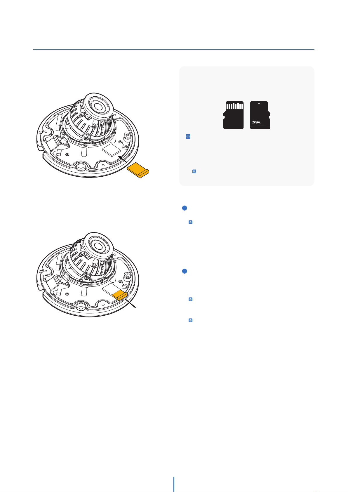
Inserting/Removing an SD Memory Card
Micro
The memory card is an external data storage device
that has been developed to offer an entirely new way
to record and share video, audio, and text data using
digital devices.
Recommended SD Card Specification (Not Included)
- Type: Micro SD (SD/SDHC/SDXC)
- Manufacturer: SanDisk, Samsung, Transcend, Micron
- Capacity: 4GB~128GB
- Class: UHS-I U3 Class 10
New Micro SD card over 64GB must be formatted
on the first use.
1Inserting an SD Memory Card
Insert the SD card in the arrow direction.
Don’t insert the SD memory card while it’s upside down
by force. Otherwise, it may damage the SD memory
card.
2Removing an SD Memory Card
Removing a SD Memory Card Gently press down on the
exposed end of the memory card as shown in the diagram
to eject the memory card from the slot.
Pressing too hard on the SD memory card can cause the
card to shoot out uncontrollably from the slot when
released.
If you have saved data in the SD memory card, removing
the SD memory card prior to setting record to OFF will
cause damage to the data stored in the card.

15
Specifications -
Dimension
Unit : mm
28.2
32.5
ø105
This manual suits for next models
1
Table of contents
Other WavestoreUSA Security Camera manuals


